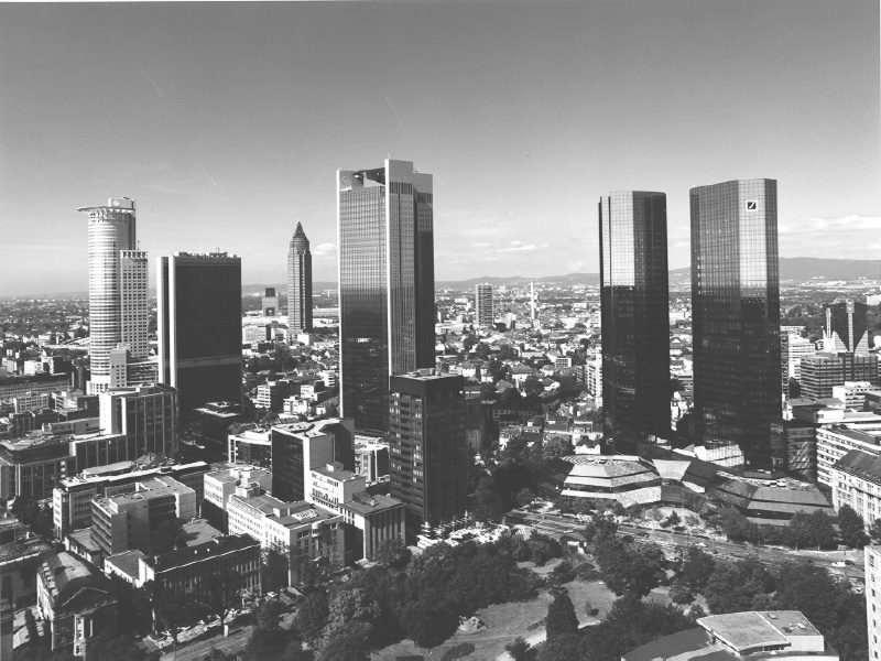
Figure 1: Snapshot of the city of Frankfurt.
Last update: Sept. 10, 2000
F. Leymarie1, A.de la Fortelle1, J.J.Koenderink2, A.M.L.Kappers2, M.Stavridi2, B.van Ginneken2,
S.Muller3, S.Krake3, O.Faugeras4, L.Robert4, C.Gauclin4, S.Laveau4 and C.Zeller4
1S2IG, Syseca,
Thomson-CSF
66, ave. P. Brossolette, F-92240 Malakoff
leymarie@lems.brown.edu
2FLUX,
Helmholtz Instituut, Utrecht Universiteit
5 Princetonplein, NL-3584 CC Utrecht, The Netherlands
j.j.koenderink@fysbb.fys.ruu.nl
3IGD ,
Visualisation & Virtual Reality Dept., Fraunhofer Institut
7 Wilhelminenstraße, D-64283 Darmstadt, Germany
Stefan.Mueller@igd.fhg.de
4ROBOTVIS
project, INRIA
F-2004 Route des Lucioles, France
faugeras@sophia.inria.fr
Proc. of IEEE «International Conference on Image Processing»
(ICIP'96),
Vol.III, pp.651-654,
P.Delogne ed., Lausanne, Switzerland, Sept. 1996.
REALISE has for principal goals to extract from sequences of images, acquired with a moving camera, information necessary for determining the 3D (CAD-like) structure of a real-life scene together with information about the radiometric signatures of surfaces bounding the extracted 3D objects (e.g. reflectance behaviour). The retrieved information is then integrated in a Virtual Reality (VR) software environment.
R&D work is been performed principally in the following areas of Computer Vision & Computer Graphics: structure from motion, recovery of geometries, recovery of photometric and texture information, highly realistic rendering on the basis of empirically-based reflectance models, design and development of improved rendering processes together with a new VR system.
Beside this innovative R&D work another key aspect of REALISE is to have Computer Vision & Computer Graphics cooperate to produce realistic 3D data efficiently.
REALISE is a three years Long Term Research project (ESPRIT project #8788) supported by the European Commission. The principal goals of this project are to provide a software prototype and (semi-)automatic tools permitting a user: (i) to extract, from image sequences (« continuous » or « discrete »)[1], pieces of information sufficient for determining the Euclidean 3D structure of a real-life scene combined with some of its photometric data, and (ii) to use this augmented 3D data in scene rendering graphics for augmented or virtual reality applications. For example, we wish to reconstruct a CAD-like 3D model of a city or a village, with texture mapping and spectral signature (reflectance) modelization added to the representation of the modelled objects. The visual input data consist in a sequence of images made of a number of snapshots taken while « walking » or « flying » around the objects in the scene.
Figure 1 shows a typical snapshot in a sequence taken near Frankfurt's downtown. In order to achieve the goals of REALISE, we have restricted ourselves to the use of cameras where non-linearities are of little impact and can be neglected (or easily estimated), i.e., we restrict ourselves to the use in normal conditions (no wide angles) of photo or video cameras commonly found on the market. No other a priori information on the camera parameters and motion nor on references about the scene are required.
This is to put in contra-distinction to the usual situation in the field of photogrammetry where similar aims for the reconstruction of 3D DB require the knowledge of absolute coordinates of control points or access to a DEM[2]; furthermore, the type of visual input considered usually requires to take into account certain of the non-linearities of the used cameras.
Figure 1: Snapshot of the city of Frankfurt.
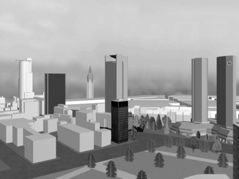
Figure 2: "Simple" reconstructed 3D model of Frankfurt.
Figure 2 shows a view (similar pose to the one of Figure 1), obtained from the « simple » reconstructed 3D model of Frankfurt's downtown, where only the main buildings were extracted using early results from REALISE's technology; further note that texture, reflectance and illumination modelling are also incomplete here.
One major challenge of REALISE is to have the two communities of Computer Graphics and Computer Vision share data in a software environment permitting the creation of 3D augmented or virtual worlds from the analysis of images or 2D projected views. Thus far, the Computer Graphics community has barely considered what Computer Vision could bring in order to improve the process of producing 3D virtual worlds, closely corresponding to real existing scenes. We also note that, it is a practical fact that the complexity of « natural » or « real-world » scenes can hardly be modelled with present-day computer graphics technology [Hildebrand96].
REALISE proposes a solution to this « hard » problem by providing, not only new techniques and algorithms, but also a common software environment. The latter permits to have a close interaction between a group of people, specialised in different key aspects of the problems at hand, from the physics of image formation, to the interpretation of images, the design of systems and architectures for 3D DB processing, and the generation and processing of virtual DB. Within REALISE we have thus designed a software architecture allowing the different partners to exchange data as well as request actions to be taken on these data. The flow of requests comes from Graphics processes toward Vision processes (to recover the geometry of the scene, to obtain texture maps, ...).
REALISE's software environment consists in an ensemble of modules that participate to one of three technological domains: Graphics, Vision and Data management. For reasons of flexibility, simplicity and to ensure the evolutivity of the developed system, a modular approach has been taken for the Graphics & Vision domains, while a client-server approach has been followed for Data management.
The Graphics domain includes modules devoted to CAD model management, colour, texture and reflectance representation and processing, as well as general illumination computation for realistic scene rendering. The vision modules are concerned with low level visual tasks (image processing: noise filtering, feature extraction - edges, corners, segments, ...), calibration tasks (retrieving the camera parameters and orientation), geometry retrieval (projective, affine or Euclidean), correspondence computations (retrieval of extracted features 3D coordinates), photometric mappings (texture mapping, interpolation,...). Data management includes the representation, storage and retrieval of data, as well as protocols of data exchange.
In this architecture, the Graphics domain is the « client » of visual routines that are resident on the Vision server (cf. Figure 3). Data management is provided through the Vision Server Interface or VSI. Mirror images of the vision data are available to both client and server sides by maintaining two identical databases (Image DB in Figure 3). This use of mirrored Image DB permits to avoid the transmission over a network of potentially large amounts of data. The Graphics client and Vision server can sit on different hardware/software environments.
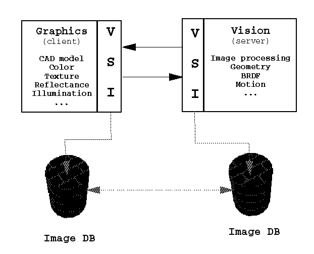
Figure 3: Schematic view of the software environment (VSI:
Vision Server Interface)
Data exchange is managed by the VSI which uses standard protocols for data representation and communication that ensure easy (and portable) data exchange procedures between different hardware/software environments.
One of the key contribution of REALISE is to provide tools for processing images (snapshots from a sequence) of the same scene in order to retrieve the viewing geometry (camera(s) parameters and orientations), as well as the scene geometry itself (of objects in the scene). In order to retrieve this « full » geometry, we follow a step-by-step approach by building a hierarchy of geometric strata, in much a classical way (mathematically speaking cf. fig4).
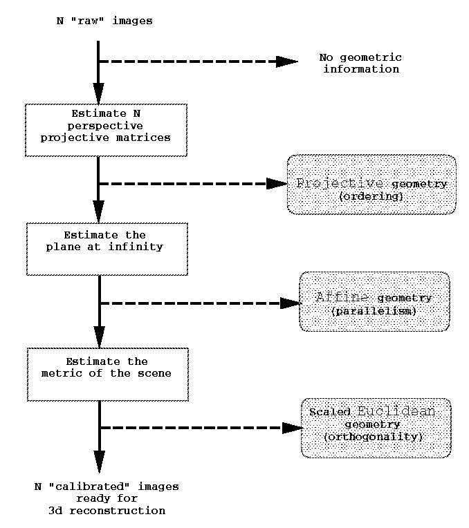
Figure 4: Recovering geometry information
We start with the projective stratum, where ordering information between 3D features in the scene is retrieved, toward the affine stratum, where information about parallelism and ratio of lengths along parallel 3D segments is retrieved, and ultimately the Euclidean stratum (up to a global scale factor), where information about angles and ratios of lengths is retrieved [Faugeras95a, Faugeras95b]. As mentioned earlier, two types of situation are possible for our intake of data, whether we obtain images in a « continuous » or « discrete » manner. In the former scenario, it is possible to use the continuity in time to ease the geometry problem: we call this scenario the M(ovie) situation. In the latter scenario, the S(napshot) situation, we must work a little bit harder. For both situations we start with a set of N images corresponding to an ordered subset of the original sequence.
The initial step for establishing the (projective) geometry of the scene consists in the retrieval of a number of correspondences between each pair of « contiguous » images in the ordered sub-sequence, i.e., we establish correspondences for N-1 pairs of images. We first extract feature points in the N images; in the context of urban scenery, corner detectors combined with a model-based approach (for position refinement) have proved useful [Blazka94]. Once feature points have been extracted from each images, we proceed to establish correspondences. In the M situation, we can take advantage of the « continuity » of the sequence by using robust tracking techniques. In the S situation the correspondence problem is harder to solve; we make use of classical (window) correlation-based techniques combined with relaxation methods in an optimisation stage.
Once the correspondences are established between image pairs, we proceed to the computation of the N-1 fundamental matrices (a convenient algebraic & parametric representation for the epipolar geometry of pair of images).[3] Correspondences between image pairs are inputted to a robust matching process (with rejection of outliers) permitting the recovery of the epipolar geometry; uncertainties are also characterised for each computed fundamental matrix Fij. The set of N-1 fundamental matrices is then used to derive a first approximation of the set of N projective matrices Pj (this requires to pick 5 points in correspondence for each pair of images which are used together with the pair of computed epipoles). Because of possible conflicts (due to image pairing) and outliers the initial set of projective matrices is further refined through the use of adapted robust methods (see [Faugeras95b] for details).
First, we note that for real-time realistic rendering of urban 3D models and virtual walk- or fly-through applications, such as is targeted in REALISE, the recovery of the projective geometry stratum proves insufficient,[4] given present day fast-rendering hardware which can only handle Euclidean descriptions. Second, we then emphasize the fact that, since all geometric relations induced by point correspondences have already been used, we must bring in new pieces of information, either on the viewing system (cameras) or on the scene, if we hope to derive more geometric structure for the image sequence at hand.
In the former case, we are lead to compute the intrinsic camera parameters. This has been done, assuming the intrinsic parameters do not vary across at least three views, but the approach has proven to be very noise sensitive.
In the latter case, we can follow two paths. Assuming we have knowledge of the coordinates of at least five « anchor » points in general configuration, we can retrieve the projective transformation which permits to go from projective coordinates to Euclidean ones. This « self-calibration » supposes however that manual measurements on the scene have been performed.
In the second approach, which can be fully automated, we first retrieve the affine stratum by extracting, in the N images, pairs of lines known to be parallel in the scene[5] and by computing the « plane at infinity ». This plane is derived from the vanishing points of the images of (at least) three sets of non-coplanar direction of lines. Retrieving the affine structure then amounts to define a projective basis set and map it on a reference (canonical) set. Five reconstructed points of the scene are required for this computation: one for the origin, three to define coordinate axes and planes, and a final one (not in the coordinate planes) representing the scaling effect along the 3 coordinate axes.
To go to the Euclidean stratum, from the affine one, we need to extract pairs of lines known to be orthogonal11 in the scene. The use of three pairwise orthogonal directions permits to « rectify » the affine coordinate basis. Note however that this « rectification » process only brings us a scaled (along the 3 axis directions) Euclidean structure where angles are preserved only for pair of lines aligned with the coordinate axes. To retrieve the Euclidean structure, up to a global scale of the scene, three « skew » parameters are introduced, to account for the non-orthogonality of the reference affine basis. A standard iterative technique then leads us to the solution (cf. [Faugeras95b]).
At this point, we have outlined a complete set of new computer vision tools developed within the scope of REALISE, that permit to compute an Euclidean (3D) reconstruction of a scene, without any prior knowledge of the camera parameters, nor the scene coordinates. We then are ready to answer further requests from the Graphics client, in order to build CAD models of specific objects in the scene.
We are developing a user interface for the client Graphics side which permits to send interactively requests to the Vision server, through the VSI . An example giving a feel for what the first version of this user interface looks like is provided in Figure 5. An ensemble of vision functions are available to the user as an help to reconstruct 3D objects easily; some of the available functions are: upon selection of one point in an image provide a pencil of epipolar lines (in the N-1 remaining images), get closest feature point (corner, edge), get 3D coordinate of an image point, get 3D (endline) segment coordinates from 2 points (in 1 or 2 images), get 3D polygon (summits) coordinates from m points, etc.
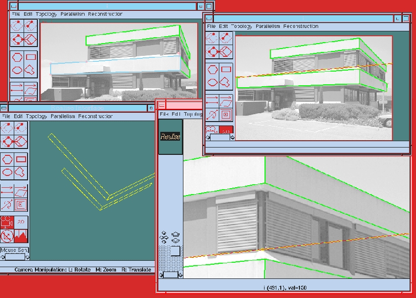
Figure 5: User interface for CAD-like model reconstruction.
To reconstruct such models
using some REALISE calibrated data, click
here. ![]()
Besides the important subject of the retrieval of the geometry which has been described in this paper, REALISE also aims at providing new methods and tools to augment the purely geometrical representation obtained thus far with information linked to the radiometric properties of the surfaces delimiting the objects in the scene, going from mapping the extracted image textures onto the 3D CAD-like models, to the tasks of characterizing the reflectance properties of a surface patch.
A particular effort is been put by REALISE on the representation and estimation of surface material properties. In order to achieve realistic rendering applications, we have set as a goal to define a concise representation of the BRDF[6] of real materials. Up to now, only abstract models have been defined in the realm of Computer Graphics, models which often are non-physical, such as the Phong shading model, or for which the link between parameters and physically-based modelling is functional, not explicit (i.e., one can model a roughness effect, not the reflectance of a specific material, such as a particular kind of brick), e.g. Ward's model [Schlick94].
In contra-distinction to the traditional approaches, we have developed a physical and empirical approach to BRDF modelling. An apparatus was built to measure « real » BRDF of materials typically found in urban scenery. The spatial distribution of scattered light in relation to the incident light determines the surface appearance and can be partly specified by the BRDF. We perform gonioradiometric measurements on samples of architectural interest (e.g. bricks, tiles, etc.). We combine models of specular and diffuse reflectance on rough surfaces to describe the reflection mechanisms in studied surfaces. We also acquire images and perform image texture statistical discrimination techniques to determine the textural differences in the surface appearance, resulting from the variation of illumination and viewing [vanGinneken96].
Because a BRDF relies on 2 independent directions (thus has 4 degrees of freedom) one typically has only a relatively sparse set of observations. In order to be able to interpolate these sparse data in a convenient and principled manner a series development in terms of an orthonormal basis is required. The elements of the basis should be ordered with respect to angular resolution. Moreover, the basis should automatically respect the inherent symmetries of the physics, i.e., Helmholtz's reciprocity and (most often) surface isotropy. We indicate how to construct a set of orthonormal polynomials on the Cartesian product of the hemisphere with itself with the required symmetry and invariance properties. These "surface scattering modes" form a convenient basis for BRDF's description [Koenderink96].
For Graphics needs, a new discrete basis has also been designed in terms of a tessellation of the hemisphere in order to produce regular data measurements to be stored in a compact matrix representation. Such matrices are then available to the Graphics client for higher realism in scene rendering. The BRDF data, corresponding to real surface properties can thus be used to complement the 3D CAD models of buildings, roads and other typical objects to be found in an urban scenery. This augmented CAD modelling permits to display mirror-like effects, retro-diffusion, anisotropy, etc. [delaFortelle96]. Some of these physical effects have been modelled before, but it is the first time that such effects are directly linked to real materials.
REALISE is not completed yet (it will end in January 1997), and we have set further goals to achieve during 1996. We are looking at the problem of identifying BRDF of surface patches of objects in the observed scene using an image sequence. We make use of the geometrical knowledge previously extracted (viewing and surface element positions). We are also looking at the problem of surface (3D) texture modelling [Koenderink95, vanGinneken96], as well as its extraction or identification from the observed scene, similarly to the approach taken for BRDF. Finally, a Virtual Reality system is being developed to exploit efficiently the information obtained through Computer Vision processes, as well as improving or optimising some Computer Graphics tasks highly demanding in terms of processing time [Reiners95].
[Hildebrand96] A.Hildebrand et al., « Closing the gap: From Computer Vision to Virtual Reality », EuroGraphics'96, France, 1996.
[Faugeras95a] O.Faugeras, « Stratification of 3D vision: projective, affine & metric representations », JOSAA, Vol.12(3):465-484, 1995.
[Faugeras95b] O.Faugeras et al., « 3D Reconstruction of Urban Scenes from Sequences of Images », INRIA TR-2572, June 1995.
[Blazka94] T.Blaszka & R.Deriche « Recover. & charact. image feat. using an efficient model based approach », INRIA TR-2422, France, 1994.
[Schlick94] C.Schlick, « A Survey of Shading & Reflectance Models », Computer Graphics Forum, Vol.13(2), pp.121-131, June 1994.
[vanGinneken96] B.vanGinneken, « Modelling diffuse & specular reflectance from rough surfaces », FLUX TR, Utrecht U., Jan. 1996.
[Koenderink96] J.J.Koenderink et al., « BRDF expressed in terms of surface scattering modes », FLUX TR, Utrecht U., 1996.
[delaFortelle96] A.de la Fortelle & F.Leymarie, « On the use of general & empirical reflect. models in computer graphics », Syseca TR, 1996.
[Koenderink95] J.Koenderink & A.J.vanDoorn, « Texture from illuminated 3D surface articulation », FLUX TR, Utrecht U., 1995.
[Reiners95] D.Reiners et al., « High-Quality
Realtime Rendering for Virtual Environments », IGD Tech.Rep.,
Darmstadt, 1995.
[1] For our purposes, a « continuous » sequence is made of images taken at high rate (like a video scan), while a « discrete » sequence is made of images taken from different view points with no time constraint.
[2] DEM: Digital Elevation Model.
[3] For a pixel in one image the
epipolar geometry provides a 1D line of search in the other image (thus
it reduces the dimensionality of the initial 2D correspondance
problem). To more about epipolar geometry
visit Sylvain Bougnoux's descriptive
webpage
on the subject. ![]()
[4] View transfer is feasible once we
know the projective geometry, i.e., new views of a scene can be
obtained for virtual camera positions without explicitly constructing
3D models. To more about calibration, try
the semi-automatic calibration tool initially developed through
REALISE by Sylvain Bougnoux:
TotalCalib
. ![]()
[5] In the context of urban scenery, parallel (or orthogonal) lines often occur, e.g. for building walls, roofs, roads, etc.
[6] BRDF: Bidirectional Reflectance
Distribution Function, defined as the directionally dependent ratio of
radiance to irradiance. A database of BRDF and associated
phototextures, recorded through REALISE in cooperation with Columbia
University is available :
CUReT . ![]()
Page created & maintained by Frederic Leymarie, 1998.
Comments, suggestions, etc., mail to: leymarie@lems.brown.edu