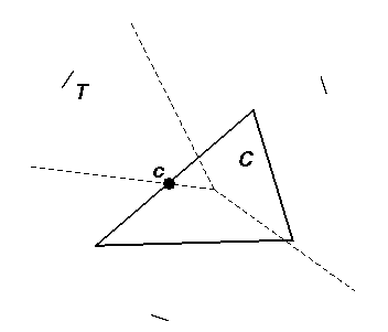
Voronoi diag. of 3 short line segments as dotted lines.
Testing if VR(T) intersects C (e.g. at c it
does).
April 3, 2000
Publications in Comp. Geom. & Graphics on Voronoi Diagrams & related concepts, as well as their applications by:
BibTeX references.
Marek Teichmann and Seth Teller
Technical Report 766, Graphics
Group, Laboratory for Computer Science, MIT, November 1997.
Summary:
A robust marching tetrahedra type algorithm for constructing a polygonal approximation of the Voronoi diagram of an arbitrary set of triangles in 3D is described.
Space is adaptively subdivided into a set of tetrahedral cells, and the set of Voronoi regions which intersect each cell is determined exactly using a simple primitive we introduce. We obtain a small number of different types of cells in which we then construct the polygonal approximation.
Applications include:
An exact method for computing the Voronoi diagram (Medial Axis) of a convex polytope in 3D with worst case running time of O(n²), for n input bounding planes, based on a reduction to convex hull in 4D, is presented.
NB: A polytope is the bounded intersection of a finite set of half-spaces of IR^n. Every polytope can also be represented as the convex hull of its vertices (or extreme points). The convex hull problem is to convert from the vertex representation to the half-space representation or (equivalently by geometric duality) vice versa.
Advantage over previous methods:
[Overmars95]: N-D space is divided into axial cells of ficed size. Voronoi diagram approximated by labeling each cube corners with label of closest object simplex, and marking cells with more than one label as being part of the diagram. Misses surfaces entering cells undetected. Uses the notion of "bisectors".
[Bloomenthal95]: Recent version of the marching cube which cannot deal with more than one vertex of the surface in a given tetrahedral cell.
The above are approximate and do not explicitly build the voronoi cells (bounded by the diagram).
[Sherbrooke95]: Medial axis of a polyhedron (exact to numerical precision, by marching along the Voronoi diagram).
Bisector of 2 Voronoi sites S & T (generators):
A bisector is a portion of either a plane, paraboloid, parabolic cylinder, cone or hyperboloid. Each bisector has two associated generator sites and one algebraic formula.
Wavefront Ft is the set of surfaces :
The wavefront is composed of planar, cylindrical & spherical sections, which intersect at Voronoi bisectors. The wavefront is a conceptual help not explicitly used/built by the algorithm; it permits to identify the different types of events that can occur.
The front is only built approximately to save computations, at the cost of considering an additional constant number of cells at each propagation step.
For any time t, there are 3 types of cells:
Incomplete cells never obtain a label from a complete cell that is further away than distance t1-t0, when t0 <= t <= t1 . If delta is the "diameter" of a cell (or max. width), then all cell entries and exits should be within a time interval of size delta.

Voronoi diag. of 3 short line segments as dotted lines.
Testing if VR(T) intersects C (e.g. at c it
does).

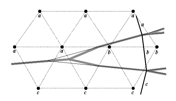
Simple approximation (in gray shade) of the exact Voronoi diagram (thin
lines).

3 labels: Only (a) get polygonized.

4 labels: Only (a) get polygonized.
Marek Teichmann and Seth Teller
in Prof. 9th Eurographics Workshop on Animation & Simulation,
August 31-September 1 (Lisbon, Portugal), 1998.
Creating articulated geometric models is a common task in animation systems. In some instances, models are procedurally instanced, and articulated degrees of freedom are designed into the model. In other instances, the model is some geometric assemblage, and an articulated skeleton (sometimes called an ``I-K skeleton'') is bound to the model by the user, typically by manual indication of a correspondence between elements of each structure. In either case, some binding must be made to couple boundary motions to those of the skeleton; this can be done for example by generating spring networks or spatial deformation fields. Both processes can be tedious in the ordinary case, especially when the model to be articulated is given only as a boundary representation, for example a polygonal mesh representing a character's skin or clothing, or an object's surface.
We have developped a simple method for assisted articulation of geometric models. Given a 3D polygonal mesh representing an object, an approximation to the mesh's medial axis is efficiently computed using a 3D Voronoi diagram of the mesh vertices, and connectivity information within the mesh. The medial axis is then simplified; the resulting tree structure has chains of edges and nodes. We interpret selected nodes as joints of an I-K skeleton, and the chains connecting them as its links. A spring network is then generated to bind the I-K skeleton to the object boundary, so that skeletal motions will affect the boundary in a reasonable way, as specified by the animator.
We show a user interface that allows interactive editing of the automatically constructed skeleton, and demonstrate the import, and mapping of key-framed motion capture data to, a variety of initially static polygonal objects. The implementation in C++ involved the use of OpenGL, the LEDA library, the XForms GUI toolkit and Ken Clarkson's Hull code.
Marek Teichmann and Michael Capps
IEEE Visualization'98,
October 1998
Generation of a three-dimensional model from an unorganized set of points is an active area of research in computational graphics. Alpha shapes can be employed to construct a surface which most closely reflects the object described by the points. However, no alpha-shape, for any value of alpha, can properly reconstruct certain regions of a model. We introduce herein two methods of improving the results of reconstruction using alpha-shapes: density-scaling, which modulates the value of alpha depending on the density of points in a region; and anisotropic shaping, which modulates the form of the alpha-ball based on point normals.
Page created & maintained by Frederic Leymarie,
1998-2002.
Comments, suggestions, etc., mail to: leymarie@lems.brown.edu