Last update: Feb. 18, 2008
BACK
|
``The first object of the painter
is to make a flat plane appear
as a body in relief and
projecting from that plane.''
Leonardo da Vinci (b. 1452,
Vinci, Republic of Florence
[now in Italy]
-d. May 2, 1519, Cloux, Fr.) |

|
|
Annunciation - 1472-75 circa - Uffizi Gallery
|
Publications on (technical) Drawing in Perspective :
BibTeX references.
Some web links of interest:
The Art Studio Chalkboard - Drawing
- Focuses on the technical fundamentals of (linear) perspective.
http://www2.evansville.edu/studiochalkboard/draw.html
The Art of Renaissance Science: Galileo and Perspective
- ToC: www.mcm.edu/academic/galileo/ars/arshtml/arstoc.html
-
Theory, History and Practice of Perspective directed by Tomás
García-Salgado
by Willy A. Bärtschi
1981.
Francis D.K. Ching
1990

Anthony W. Griffin & Victor Alvarez-Brunicardi
Prentice Hall, 1998. 326 pages.
Notes
Ch.6 Two-Point Perspectives

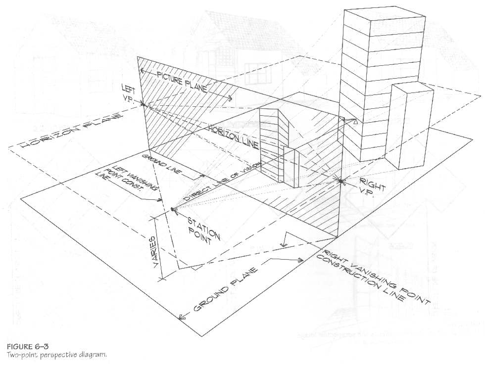
Picture Plane (image plane)
- Imaginary transparent plane onto which the object is being
projected.
- Any part of an object that "touches" the picture plane will
be to scale; hence:
- It is always to one's advantage to locate the picture
plane such that is passes through a corner of the object being drawn.
- Gives you a true height-line, from which all vertical
heights can be measured.
Direct Line of Vision (principal line)
- Imaginary line from the Station Point to the Picture plane
(perpendicularly).
- It should be located so as to intersect with some point of
interest on the building.
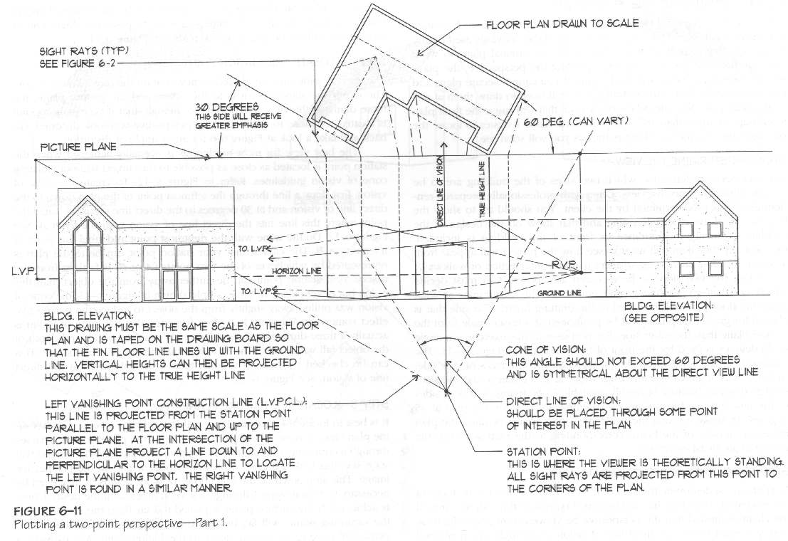
Station Point (Camera Station)
- If the station point is too close to the picture plane, the
perspective view becomes overly "distorted"; to prevent this, use the
"cone of vision".
Cone of Vision
- Station Point as vertex. Opening angle usually varies
between 30 and 60 degrees.
- Most of the object of interest should be within the cone to
avoid distortions.
- 3D cone: not only width and depth, but also height of the
object of interest should fall within this cone.
Sight Rays
- Used to project points from the plan to the picture plane
and then down to the perspective.
- They must always originate from the Station Point.
Plan View (Floor Plane)
- This is a floor plane drawn to scale, viewed from above
(aerial viewpoint), upon which are plotted points.
- It can be plotted above or below the actual perspective
view.
Plan Angle (azimuth)
- Angle between the floor plan and picture plan.
- This angle determines the emphasis put on each primary sides
of the object.
Ground Line
- Intersection of the Ground Plane and the Picture Plane.
- All vertical measurements are taken from the Ground Line.
Horizon Line
- Line formed by the intersection of the Horizon Plane and the
Picture Plane.
- The height of the horizon line corresponds to the eye-level
height of the observer.
- The location of the horizon line determines whether you will
be looking down or up to the object being drawn.
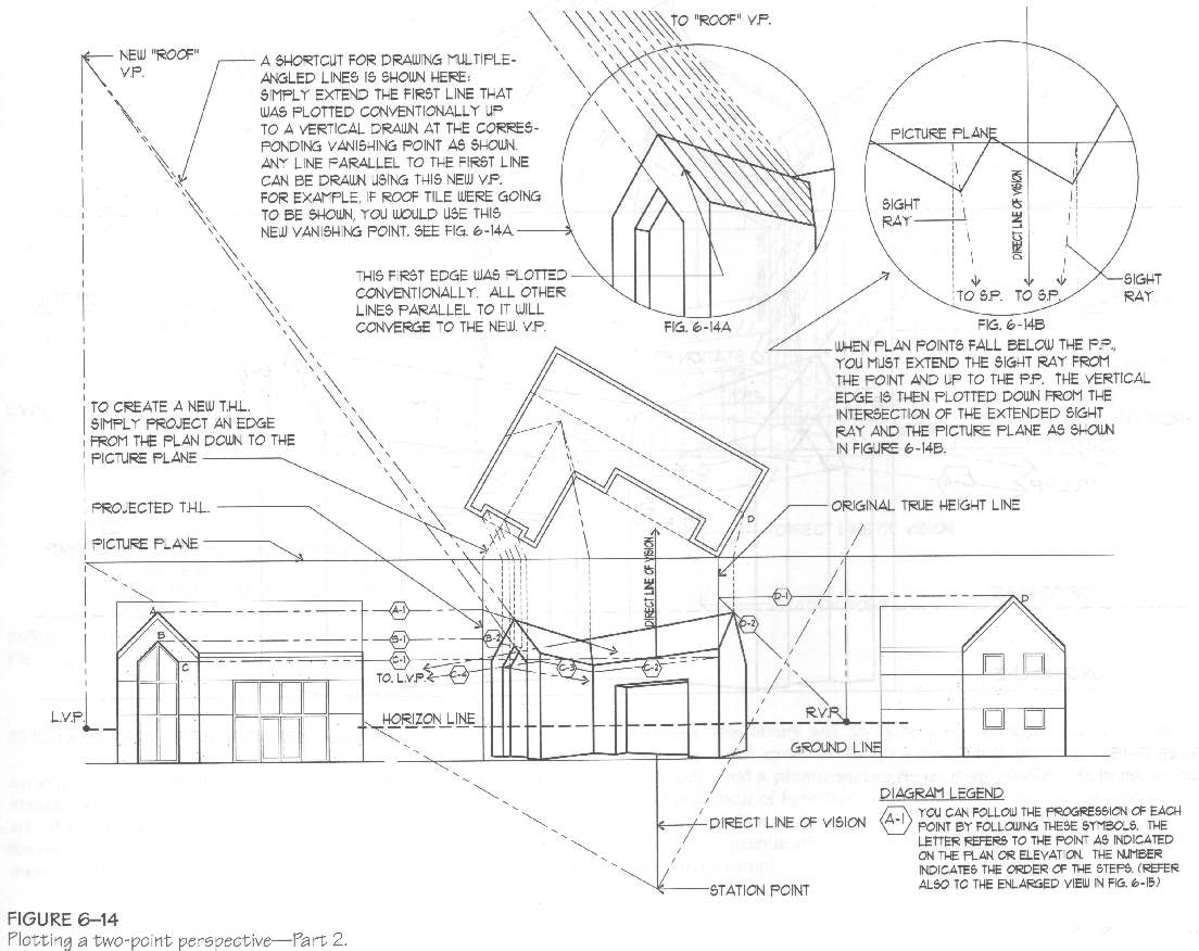
True-Height Line
- Occurs whenever a part of the object touches the picture
plane.
- True-Height Lines can be located at any point in the
perspective view simply by projecting a point from the plan to the
picture plane (central projection w/r to the Station Point). A
perpendicular is then projected from the picture plane down to the
Ground Line.

Ch.7 One-Point Perspectives
- Plan Angle is always parallel to the picture plane.
- Objects that touches and are parallel to the picture plane
are drawn in a simple orthographic view.
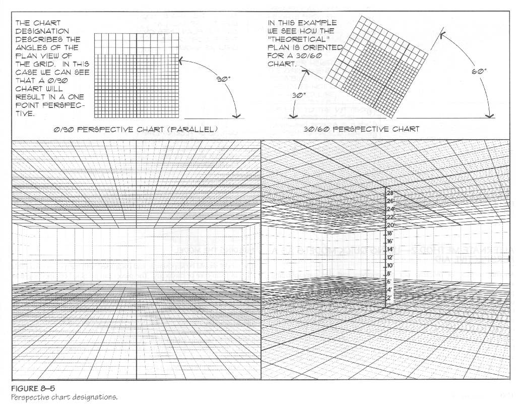
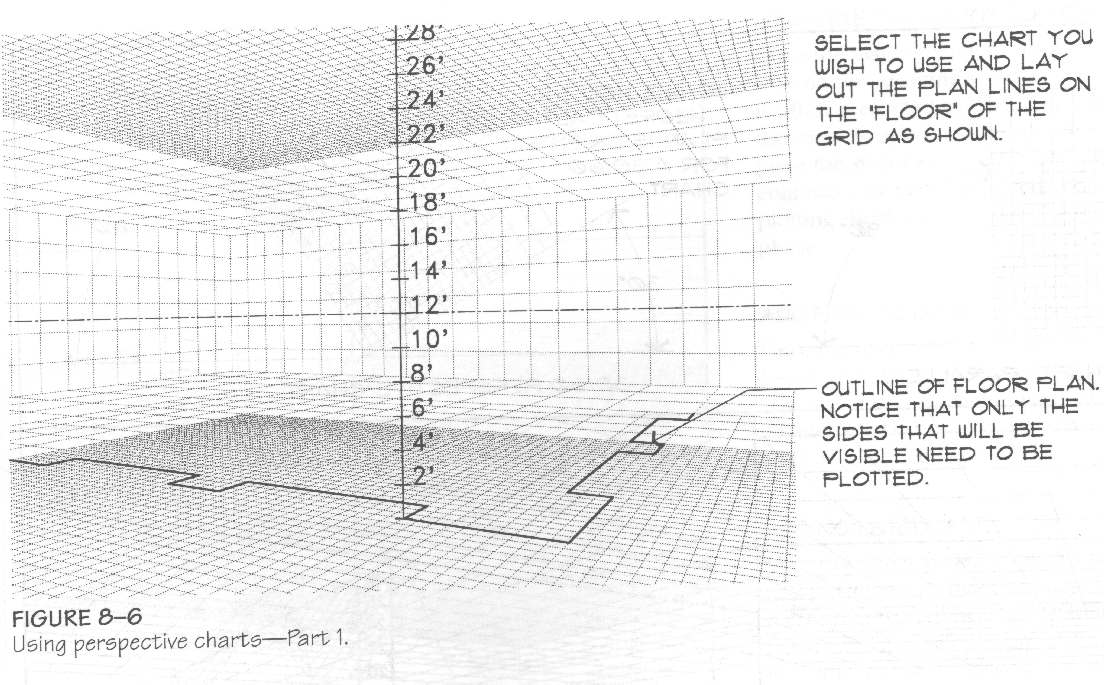
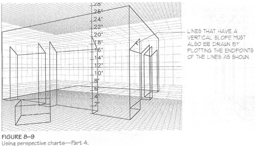
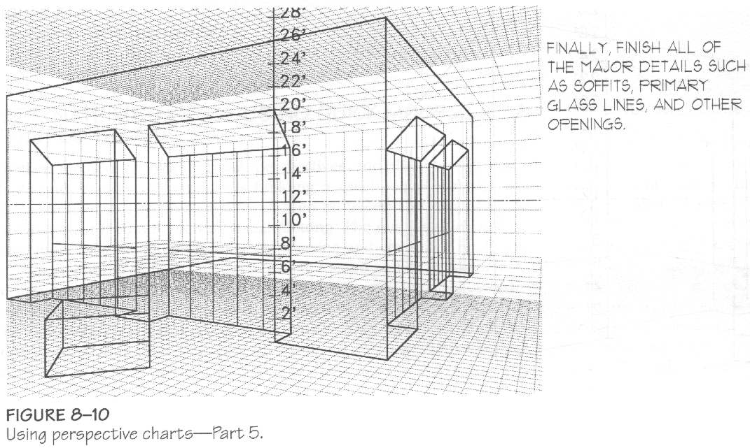
Ch.8 Alternate Perspective-Plotting Methods
Perspective Charts
- Use a pre-defined perspective grid and a vertical unit scale
(that scale can always be re-adjusted through multiples).
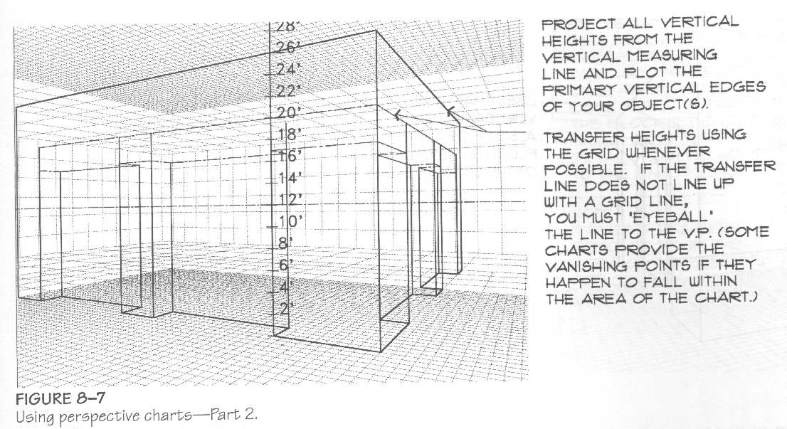
- Each chart is identified with an angle value representing
the plan position of the object in relation to the picture plane.
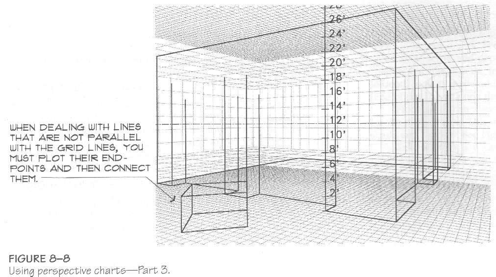
- Most commercially available charts come in:
- 3 plan angle configurations: 30°/60°, 45°
& 0° (the latter corresponds to a 1PtP).
- 3 view types:
- normal (distance of 5 to 6 feet between the Horizon
and Ground Lines)
- intermediate (taken from a height of 10 to 15 feet
for producing 2nd-floor views).
- bird's eye view (large height)


Photographic Perspective
- Uses photos or videos of existing buildings.
- Additions and/or renovations can be drawn using VPs within
the photograph.
- Use a measuring device (tape, rope, ...) to provide accurate
scale info. in the photo.
Page created & maintained by Frederic Leymarie, 1998-2008