Hardware Implementation
It was decided to use two Sony PlayStation Eye cameras. This device has been designed to be used in various real-time image processing and object tracking applications such as The Eye Pet so seemed the ideal choice for the needs of the project due to its unusually high capture frame rate (60 hertz at a 640×480 pixel resolution, and 120 hertz at 320×240 pixels).

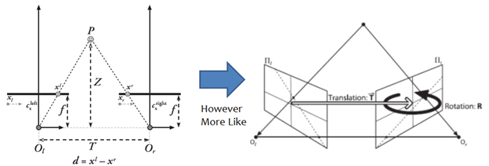
Fig 1. Perfect Pin Hole Camera model (left) and Distorted Stereo Camera (right)
By using two cameras, it is possible in the software to calculate the depth of field. Just as the human brain uses binocular disparity, which is the difference in image location of an object seen by the left and right eyes, to extract depth information from the two-dimensional retinal images in stereopsis, it possible in computer vision to use the disparity of features between two stereo images which is usually computed as a shift to the left of an image feature when viewed in the right image (correspondance). With a perfectly undistorted, aligned stereo rig and known correspondence, the depth Z can be found by using similar triangles (see left image in figure 1). However in practice the cameras will not be perfectly aligned nor free from lens distortion (see right image in figure 1). To correct this mathematically, the OpenCV library provides a number of functions which enable the system to carry out the following procedures:
- Undistortion – to correct deviations from pin-hole camera
- Radial Distortion – lens shape
- Tangential Distortion – lens not parallel to plane
- Rectification – align & adjusting distance between cameras
- Correspondance – find same features in left & right camera views, resulting in disparity map
- Reprojection – now known geometry, turn disparity map into distances using triangulation
Software Implementation

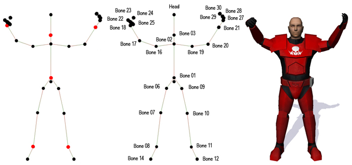
Fig 2. End effectors marked in red (left), Skeleton with named bones (centre) and corresponding Skinned Mesh (right)
The central image in figure 2 shows a skeleton of a skinned mesh; this type of structure is created from several bones linked together in a hierarchical fashion. A bone usually has a parent bone and zero or more child bones. Any transformations applied to a parent bone also affect its children (and their children, and so on). After you have built or loaded a hierarchical bone structure, you can then apply a mesh to it so that each vertex in the mesh is linked to one or more bones as is shown in the right image of figure 2.
The system implements an inverse kinematic solution to the problem of mapping the user's movements to that of the skeleton of the skinned mesh. The principle of an inverse kinematics solution to a motion problem is that, given a position in world space and the end point of a linked chain (the end-effector, as marked in red on the left image of figure 2), determine the rotations that have to be applied to the linked chain in order that the end effector reaches the goal. Most of the study of this problem stems from robotics. Each joint can be rotated in one or more directions. A single joint that rotates in the heading, pitch and bank is described as having three degrees of freedom (3 DoF). For an object to be completely free moving, it must have six degrees of freedom (6 DoF).
The solutions to IK problems can be divided into two categories; analytical and numerical. Analytical solutions are generally the preferred way for simple IK chain with few links as they have an equation that can be solved directly. Numerical solutions attempt to find approximate (but somewhat accurate) solutions to the problem. The approximations are usually done by either iterating over the result, which finally converges toward the solution, or dividing the problem into smaller, more manageable chunks and solving those separately. Numerical IK solutions also tend to be more expensive compared to their analytical counterpart. The system uses analytical solutions (such as the Law of Cosines Algorithm).

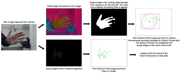
Fig 3. Procedure for determining the position of the end-effector of the hand and a comparison of the results of using the Adaptive Skin Threshold algorithm
To track the movement of the hands and head of the user, it is necessary to try and segment the figure from the background with a reasonable level of accuracy to avoid false positives. This movement of the user can then be analysed and the end-effectors of the head and hands can be mapped onto the skinned model. The system assumes the user is not wearing gloves nor a short sleeved shirt so that there will usually be three areas of flesh tone present, the head and the two hands. Figure 3 shows a comparison between the two techniques adopted for this purpose; using OpenCV's Adaptive Skin Threshold algorithm and converting the image to Hue Saturation Values (HSV) and limiting the range. Once these regions of interest have been determined, it is necessary to determine which one is the head end-effector and by a process of elimination the two others must be the hand end-effectors. This is achieved by using the Haar classifier, which builds a boosted rejection cascade. OpenCV implements a version of the face-detection technique first developed by Paul Viola and Michael Jones commonly known as the Viola-Jones detector and extended by Rainer Lienhart and Jochen Maydt to use diagonal features.