
Figure 1 : Defining elements of airfoil.
A cross-sectional slice of any wing is an airfoil or section, shaped in a manner which attempts to optimize the balance of maximal lift, the force which causes the wing, and hence the plane, to rise, and minimal drag, the force against the rising motion. Airfoil theory has been studied extensively, with hundreds of different airfoils whose lift and drag coefficients are known being availiable to the designer. We have chosen to reconstruct one of these predetermined airfoils using the two-dimensional MAT, and then to extend the airfoil into three-space in an appropriate manner to generate an MAT representation of the airplane wing.

Figure 1 : Defining elements of airfoil.
Figure 1 shows some of the essential elements which define an airfoil. The chord is the line connecting the two extreme points of the section, shown as a solid line in the figure. Traditionally, all other measurements of the section are made relative to the chord and are quantified as a percentage of the chord length. The chord itself is generally divided into a number of stations at which the other measurements are given, and the stations are given as percentages of the chord length, so that the specification of the airfoil is independent of its length. The other measurements needed to specify the section are the thickness through the section and the camber in either direction through the section. Both of these measurements are made perpendicularly to the chord, with the camber being a one-to-two relationship giving the distance to the top and the bottom surfaces of the airfoil. The thickness is the sum of these distances. Two locations in the airfoil which are often used to differentiate between aerodynamic properties of different airfoils are the point of maximum thickness, and the point of maximum mean camber. The latter is the distance from the chord line to the medial curve of the section, shown here in dashed line. The maximum thickness and maximum mean camber are indicated in the figure by t and m, respectively. The leading edge and the trailing edge of the airfoil are also shown.
Typically, the airfoil is specified by giving the upper and lower cambers along the chord either as a discrete set of distances, or as a continuous equation. The latter is referred to as the thickness form of the section. At the leading and trailing edge, the airfoil is usually modified so that the section has a rounded tip at both ends.
For our airplane wing example, we have chosen to derive an airfoil from the data for the N.A.C.A. (National Advisory Committee on Aeronautics) 23012 section. This airfoil was developed in 1935, and has the geometric characteristic that its maximum mean camber is located at 15% of the chord length, measured from the leading edge. This is much further forward than the airfoils previously considered, which generally had their maximum mean cambers in the 30--40% range. Its location of maximum thickness is at 30% of the chord length, which is fairly typical, and the thickness is 12% of the chord length, a medium thickness for an airfoil. The data is given in tabulated form for 18 stations of the section. A reproduction of the airfoil data from [2] is shown in Figure 2.
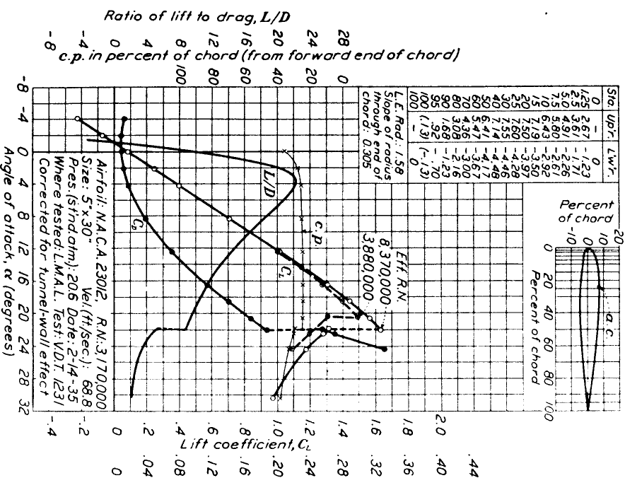
Figure 2 : Data for N.A.C.A. 23012 Section.
To use the MAT to represent the airfoil, the median curve and the distance from the median line to the boundary are required. In Figure 3, (a) through (d), we show the various steps of this construction. Figure 3 (a) shows a reproduction of the actual airfoil we are approximating. To find the median line of the airfoil, we computed the mean camber for each station. For the N.A.C.A. 23012, the curve so computed is shown in Figure 3 (b). Notice that its maximum occurs at 15% of the chord length, as desired. Also, we began at the second station, or 1.25% of the chord length in order to obtain the desired rounded leading edge. We then approximated the distance to the boundary by one-half the thickness at each station. A view of the xr-plane is in Figure 3 (c). Its maximal point occurs 30% of the way from the leading edge of the airfoil, and is 15% of the length of the airfoil. Finally, Figure 3 (d) shows the reconstructed airfoil, which is strikingly similar to the original airfoil.
(a) Original N.A.C.A. 23012 airfoil. |
|
|
|
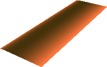
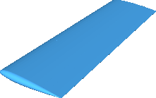
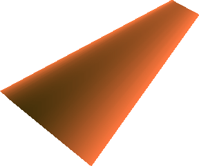
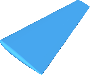
Having developed an airfoil, we are now in the position to be able to construct the wing itself. The wing can be defined as a series of airfoil sections starting with the root section which is the middle section of the wing, and ending with the tip section at the furthest extremes of the wing. The span of the wing is the length of the wing from tip section to tip section, and is denoted by b. The area of the wing is given by S, and the aspect ratio R is computed as b*b/S. The wing span and the aspect ratio play an important role in the aerodynamic properties of the wing, with a higher aspect ratio drastically improving the lift to drag ratio. However, structural considerations do not allow for excessively large aspect ratios. The wing we develop here is actually half of a wing, starting at the root section and going to one of the tip sections. The symmetry of the wing about the root section makes this a complete specification of the wing. We began with the root section and the tip section both being of length 100, and the distance between them being 300 units. This gives a strictly rectangular wing, whose MAT is shown in Figure 4. The fourth coordinate, that is the r-coordinate, of the MAT is visualized here using color, with darker colors indicating larger r values and brighter colors indication smaller r values. The wing itself is shown in Figure 4. The aspect ratio of the wing in this form is 6. We then tapered the wing along both the leading and trailing edge so that the tip section has length 50 units, thus increasing the aspect ratio to 8. Since we used the same airfoil for both sections, this tapering of the chord length of the airfoils also has the effect of tapering the thickness of the wing. The tapered wing and its MAT are shown in Figure 5.
 |
 |
 |
 |
Obviously there is much room for variation in this design. A few such changes are the airfoil sections at the root and the tip could be different; the tapering effect could be larger or smaller, and could be offset more or less from the leading edge; the tip of the wing could be modified so it is rounded; more sections could be introduced throughout the chord to give a non-linear progression from the root section to the tip section. Any of these modifications would be simple to effect with the MAT representation.
[1] T. P. Faulconer. Introduction to Airplane Design. McGraw-Hill Book Company, Inc. New York and London, 1942.
[2] Comprehensive Reference Guide to Airfoil Sections for Light Aircraft. Aviation Publications, Appleton, WI, 1982.
[3] E. P. Warner. Airplane Design: Performance. McGraw-Hill Book Company, Inc. New York and London, 1936.