 |
 |
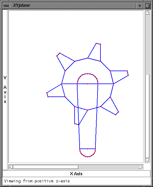
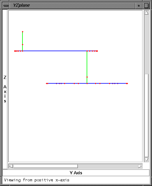
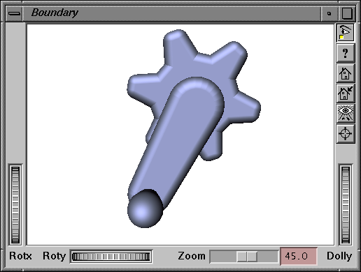
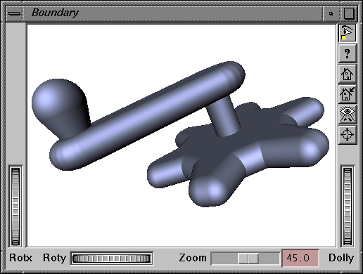
An example of how the MAT might be used to design an object is the gear with a crank and handle attached, which is shown in Figures 1 and 2 below. Figure 1 displays two of the projected views of the MAT, while Figure 2 shows two views of the related boundary. We began by designing the gear itself, and decided that the gear would have constant thickness and that it would have six teeth. Thus the MA we started with was a planar disc with twelve sides, to which we then added the teeth of the gears. After assigning a constant thickness and generating the boundary, we were able to easily modify the length of the teeth and the angle the teeth made with the disc in order to obtain a boundary with the desired spacing between the teeth.
 |
 |
After the gear met our specifications, we added the axle to connect the gear to the crank. This axle is the lower vertical line in the second figure in Figure 1. We chose to make the axle have constant radius throughout, and not to blend the axle into the gear or the crank. Note, however, that a conical blend is easy to generate with the MAT.
We next formulated the MAT for the crank. We chose to have the crank have uniform thickness, and we also began with it having uniform width. Later we decided to taper the crank at the end, and modified the MAT accordingly. Finally, we added the curve MAT component necessary for the handle on the crank. Initially we assigned a constant thickness to the handle, but then decided a knob would be more desirable and modified the radius function of that segment of the MAT so that it increased from the crank to the end of the handle. The final result of this is shown in two views in Figure 2.
 |
 |