


Balancing robots
By: Laura Traver
The project
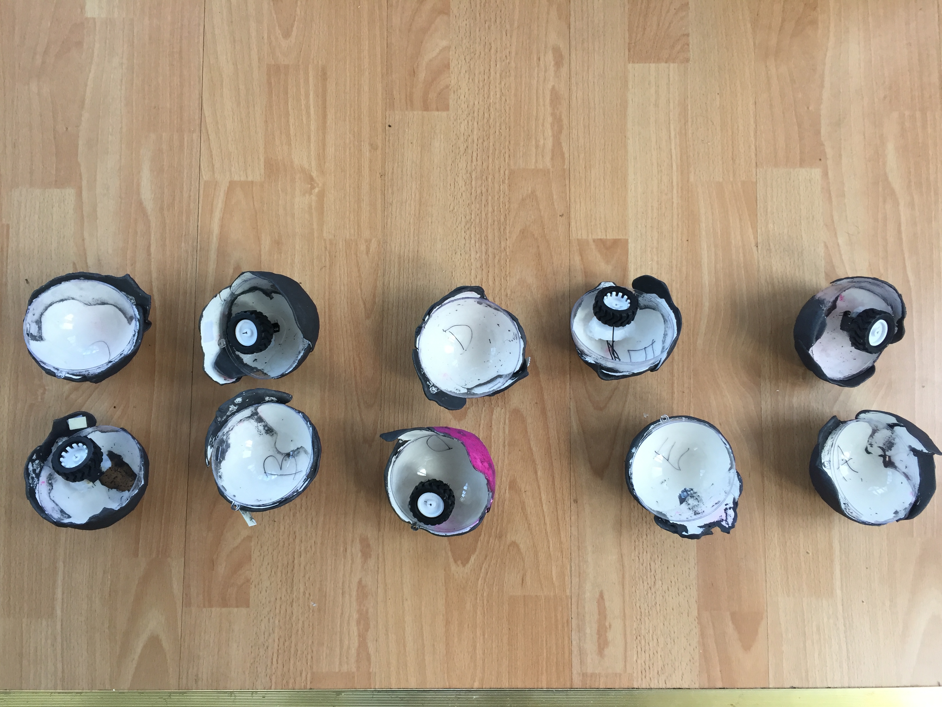
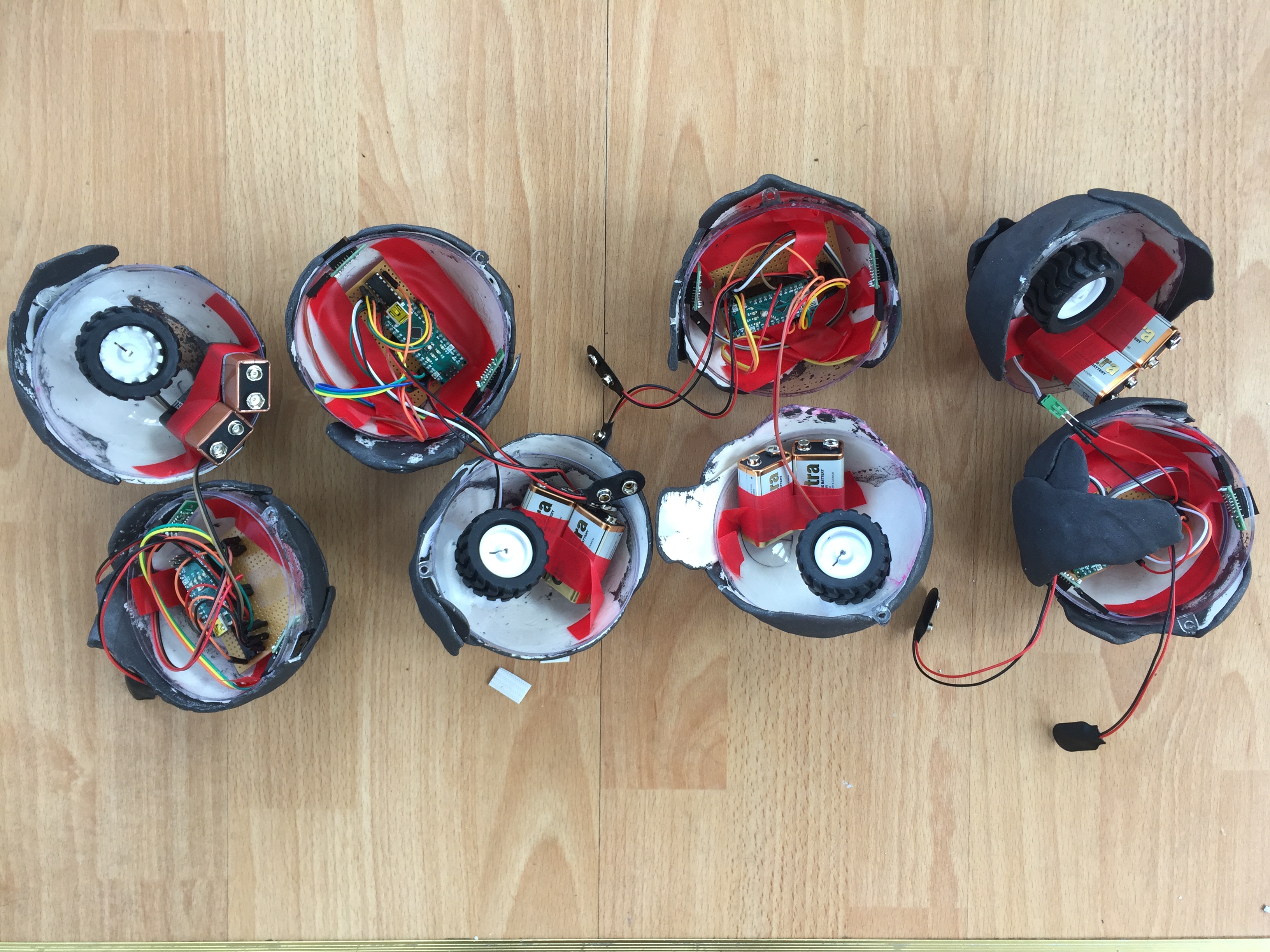
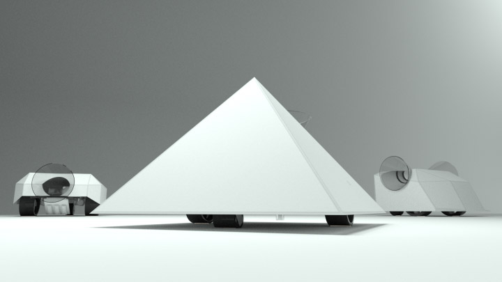
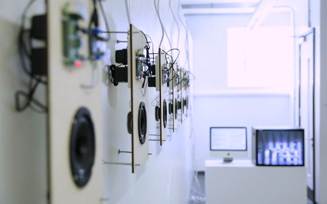
Five single-wheeled, balancing robots were made for this project. They currently use infared detection sensors to detect objects, and they are intended to also use radio communication and sound sensors for added interactive complexity. They respond to each other in that they move away from other robots and objects.
Background
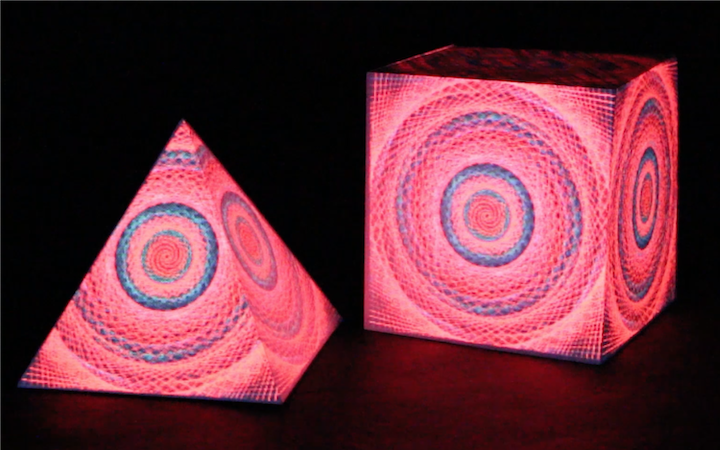
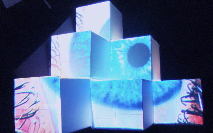
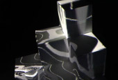
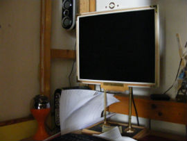
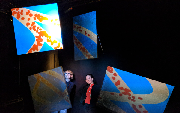
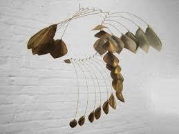
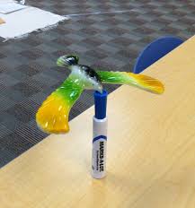
I was initially focused on the idea of patterns and color and the concept of making a moving pattern, rather than an optical illusion, and also learning how to use motors. I looked at mobile sculptures (pictured) such as by Alexander Calder and general optical patterns. I was also drawn to Heimo Zobernig's Untitled work (2015, pictured) and the idea of making shapes pop out of an object. This quickly moved into moving sculptures such as The Source at the LSE and kinetic work such as by Anthony Howe's (video below) because they are highly-visual and complex, but also simple and effective. I decided upon a mono-wheeled robot because I knew it would be a challenge and I would learn some useful skills.
Planning the form of the robot
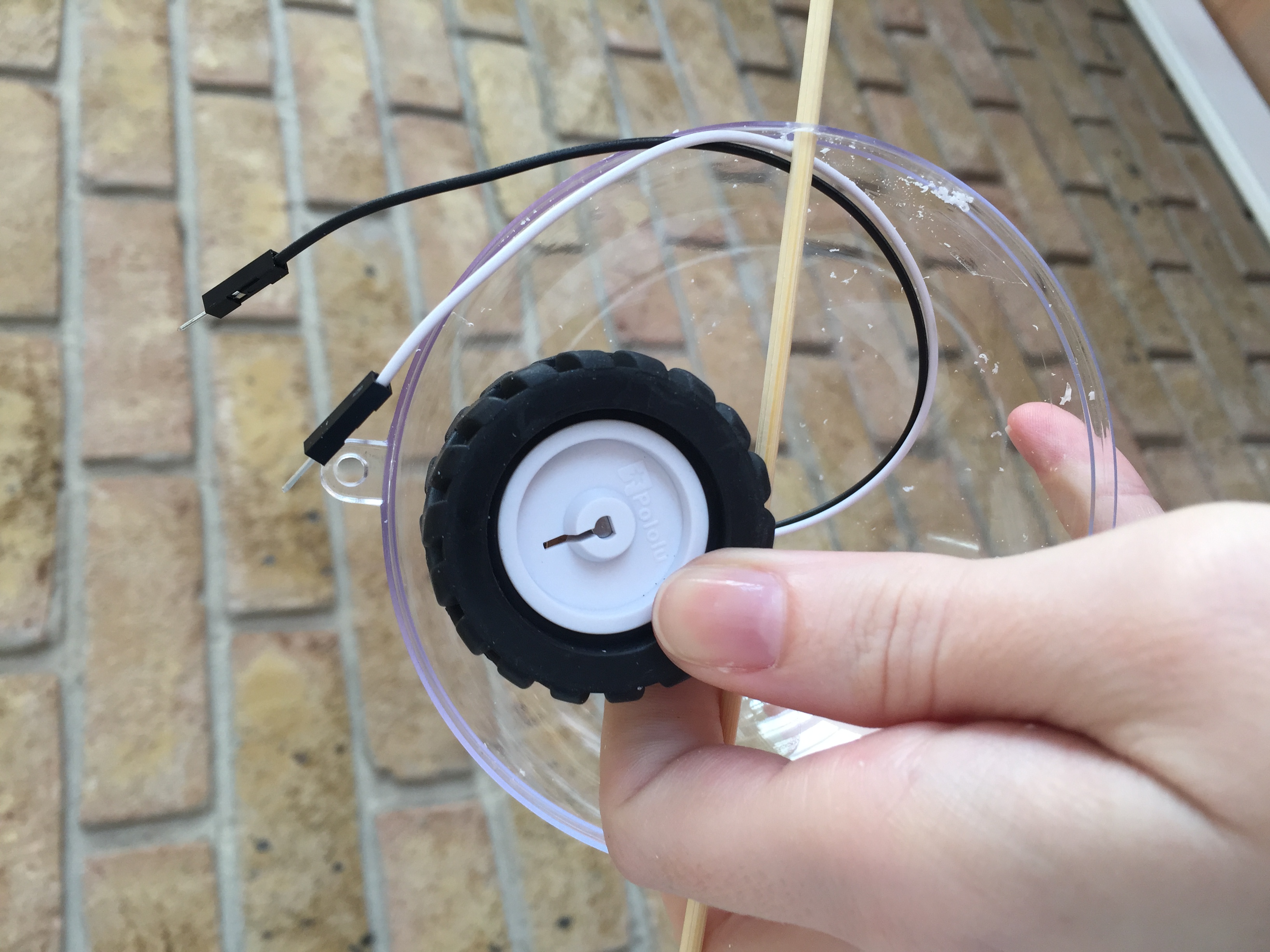
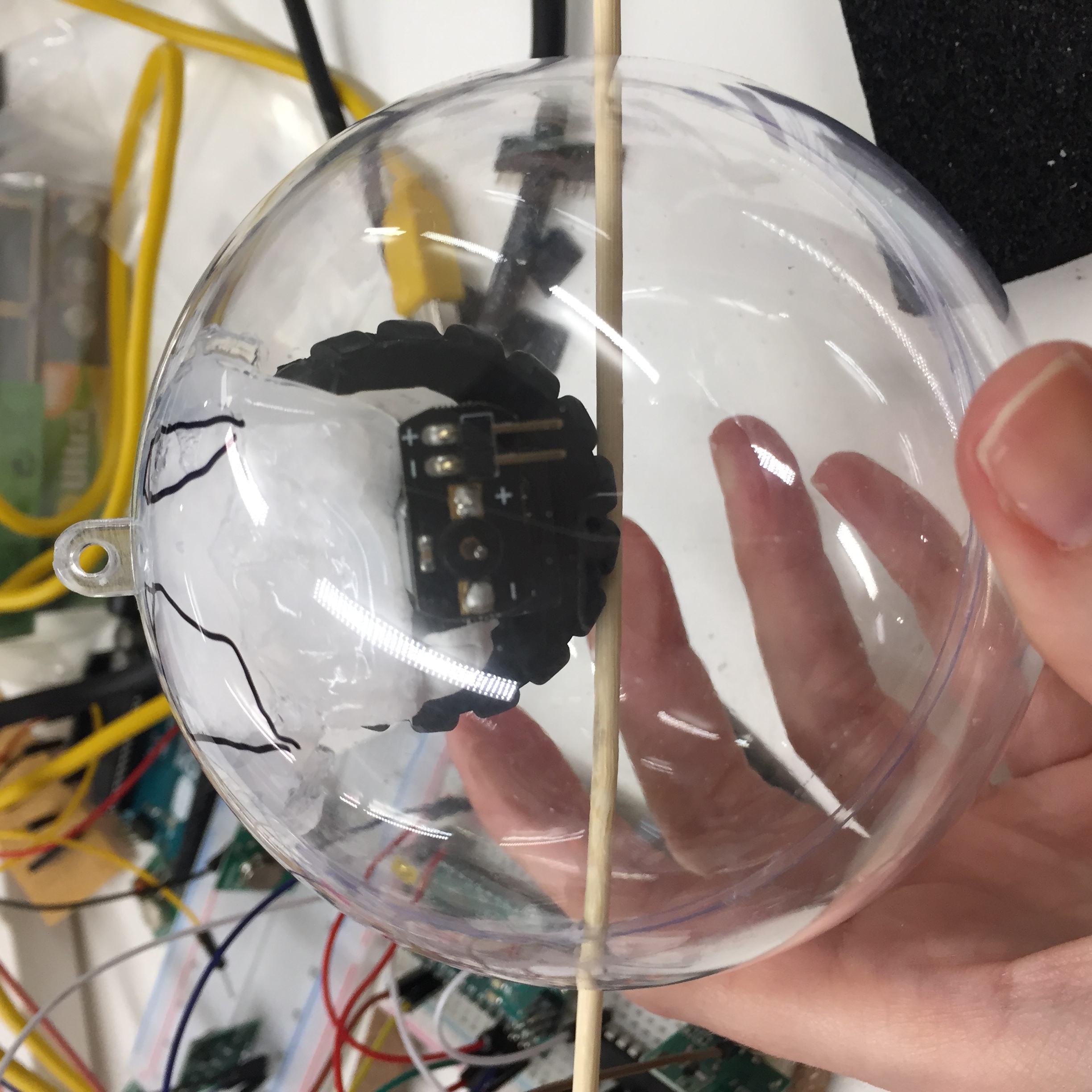
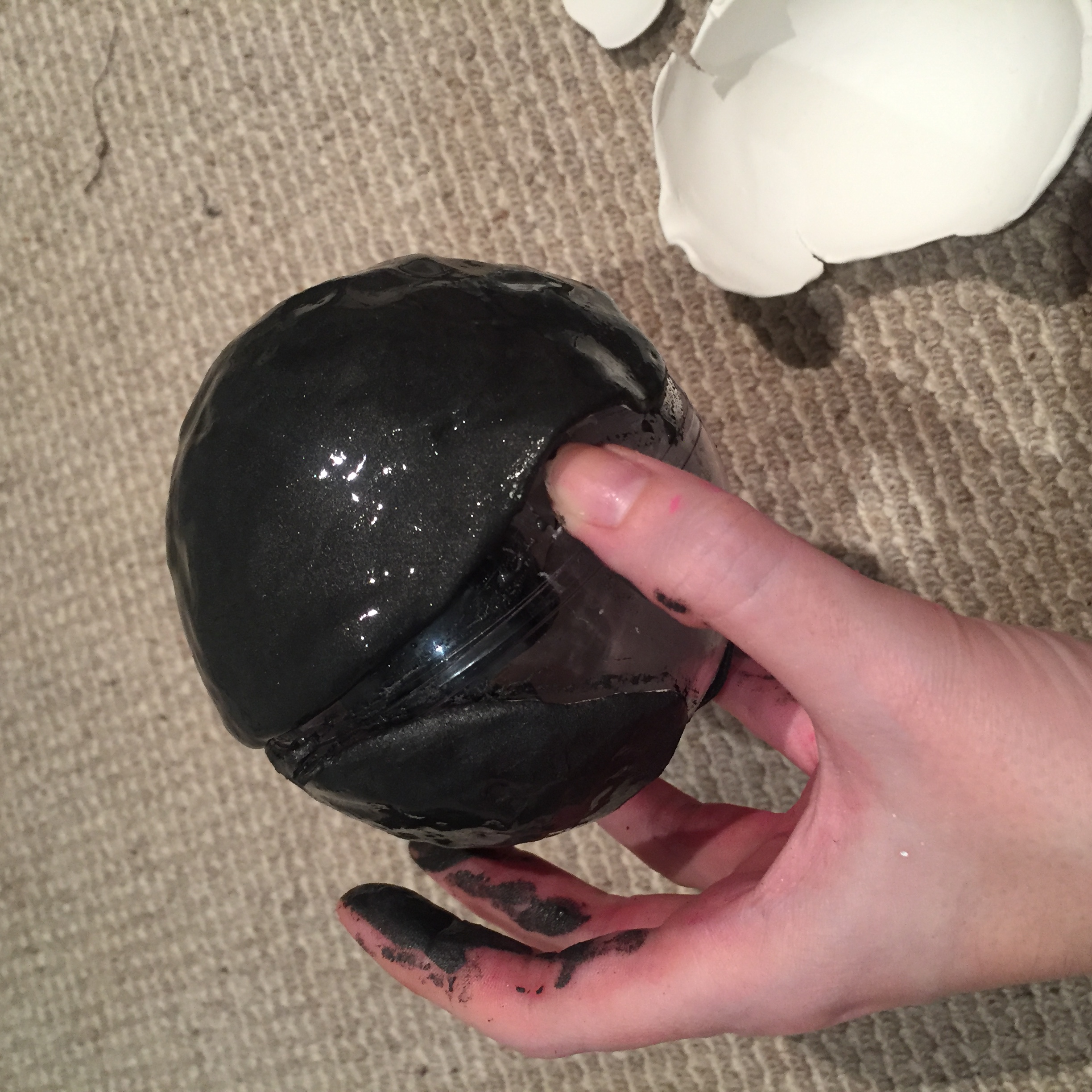
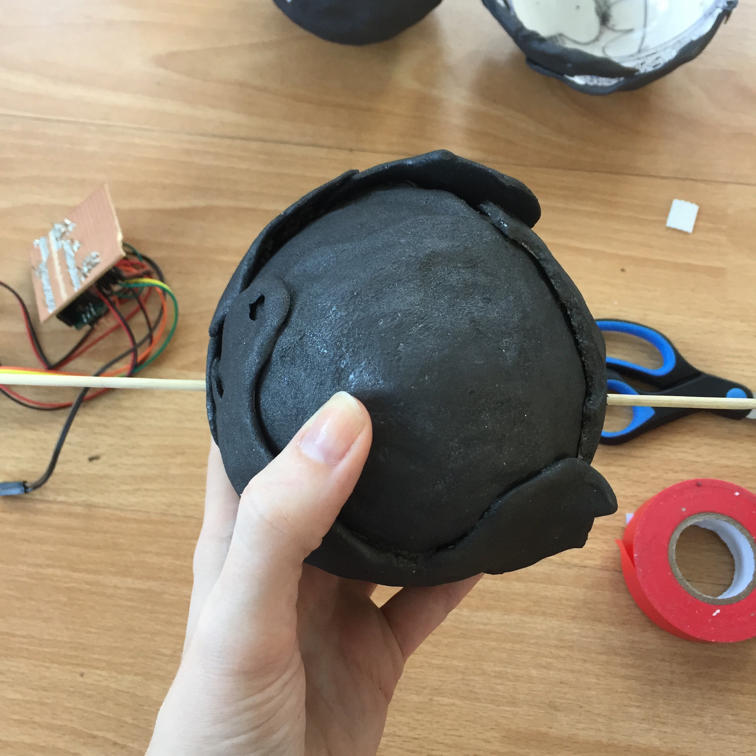
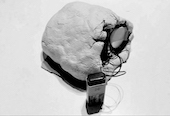
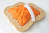
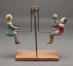
I began planning the shape immediately because this was the area I was most uncertain about being able to achieve initially. I explored old wooden balancing toys (pictured), and found a youTube video of a man balancing a motorcycle using a balancing beam in the same way as the wooden toys and who had also dug the wheels out a bit to facilitate balance. I spent a lot of time thinking about the shape and planning it in my mind in this way and decided upon a ball shape as the most simple to do for the first attempt. The shape of the ball would both contain the electronics, and also serve to structure the balance of the shape. Having wheels much wider than the wire they were on, and by feeding the wire through a hole in the ball like a track, it would be impossible for the shape not to stay on track. I ordered lead weights in case they were needed to add additional weight to pull the ball down, drop the center of gravity, and stop the shape spinning upside down. There were a lot of unknowns. I also carefully researched the wire that would be needed and decided upon a plastic coated steel wire to ensure that the rubber wheels had good grip on the plastic and also that the movement was smooth and strong. I researchced the ball shape in detail, including giant ping pong balls, and decided that large, fillable plastic Christmas baubles were probably the most straightforward object to use.
In the end, I decided upon 3 levels of shape based on complexity. The first and most simple is the ball shape I have used as the least likely to fail in terms of balance, and it is also the largest option to allow me to experiment with how to fit the electronics. The second level of shape is one that balances using a balance beam and grooves in wheels. I considered this to require more experience of the components and how to fit them in the smallest possible space. I also decided that the electronics might potentially have to be vertical and decided this was too big of a jump in the time I had. The final level is an electronically balancing shape using accelerometer's and gyroscopes. I am not sure I am interested in this type of robot at all, as I like the simplicity of the kinetic element. However, it would be very interesting to motorise a physical, rather than electronic, gyroscope and incorporate that.


The motors
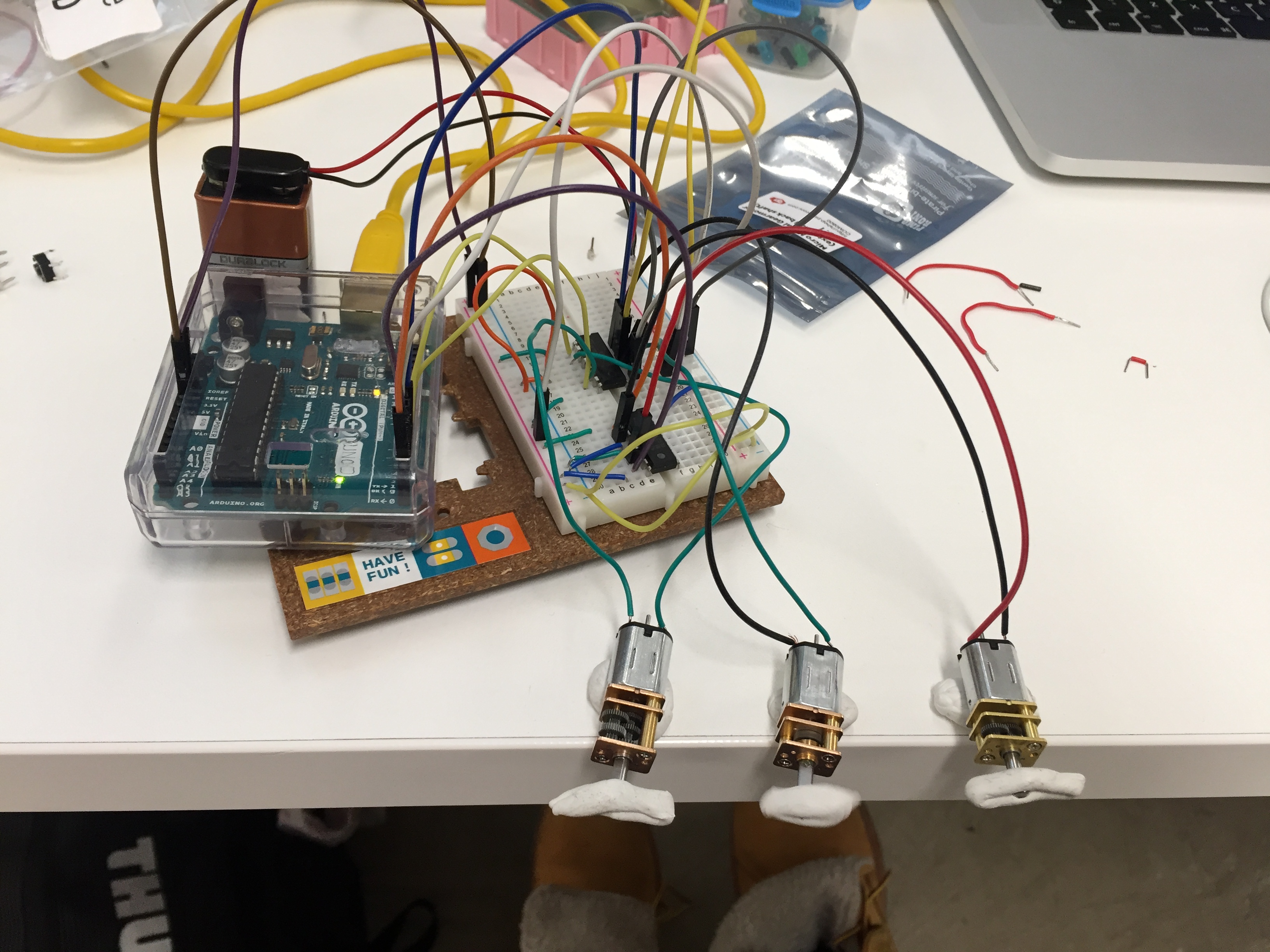
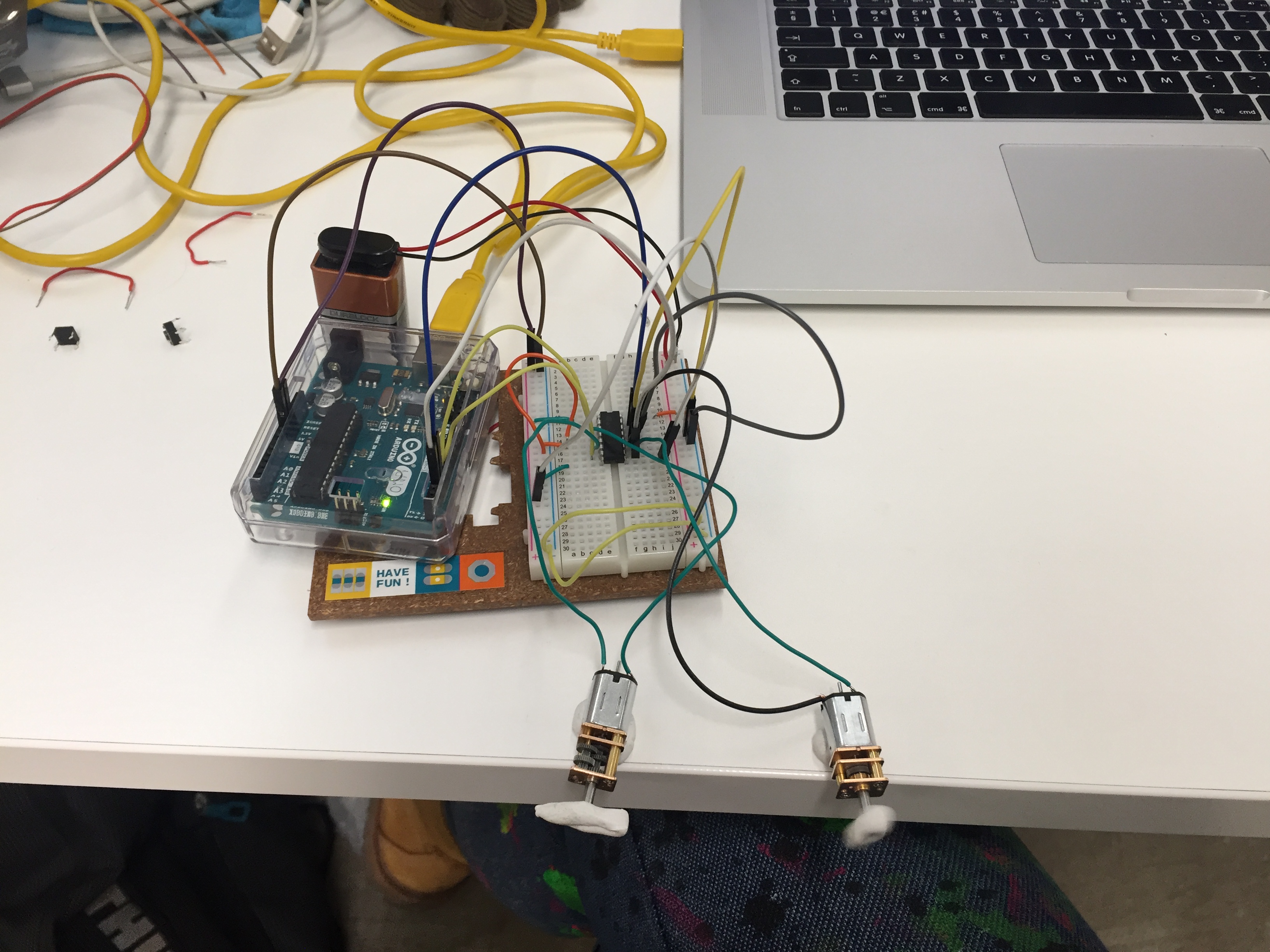
I also began to experiment with motors. Having never used them before I tried out stepper motors, which I did not like as they were noisy and I did not want to be able to control the exact movement of the motors. I also ordered micro metal gearmotors. I ordered the fastest: 11.1 at 1800 rpm, the slowest: 1006:1 at 14.2 rpm and in the middle 50.1 at 420 rpm to get an idea of what the speeds actually looked like. I decided on the slowest because I like the calmer, more subtle movement and it also had a higher torque due to its slower rate which provided more flexibility.
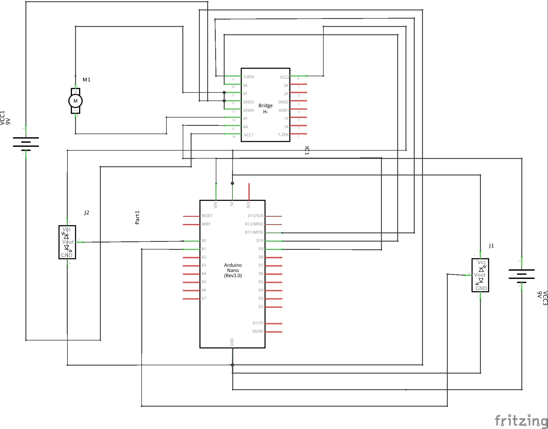
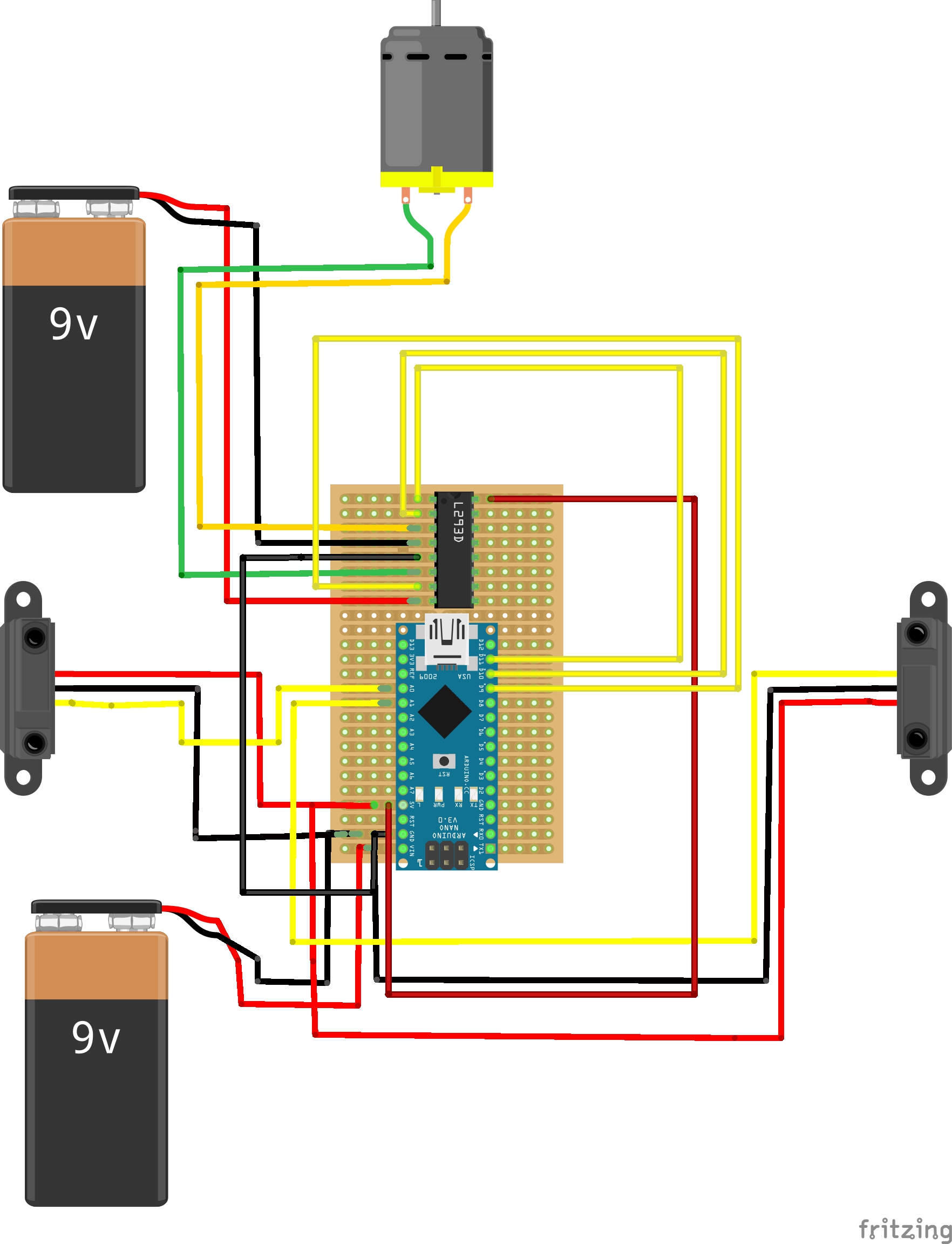
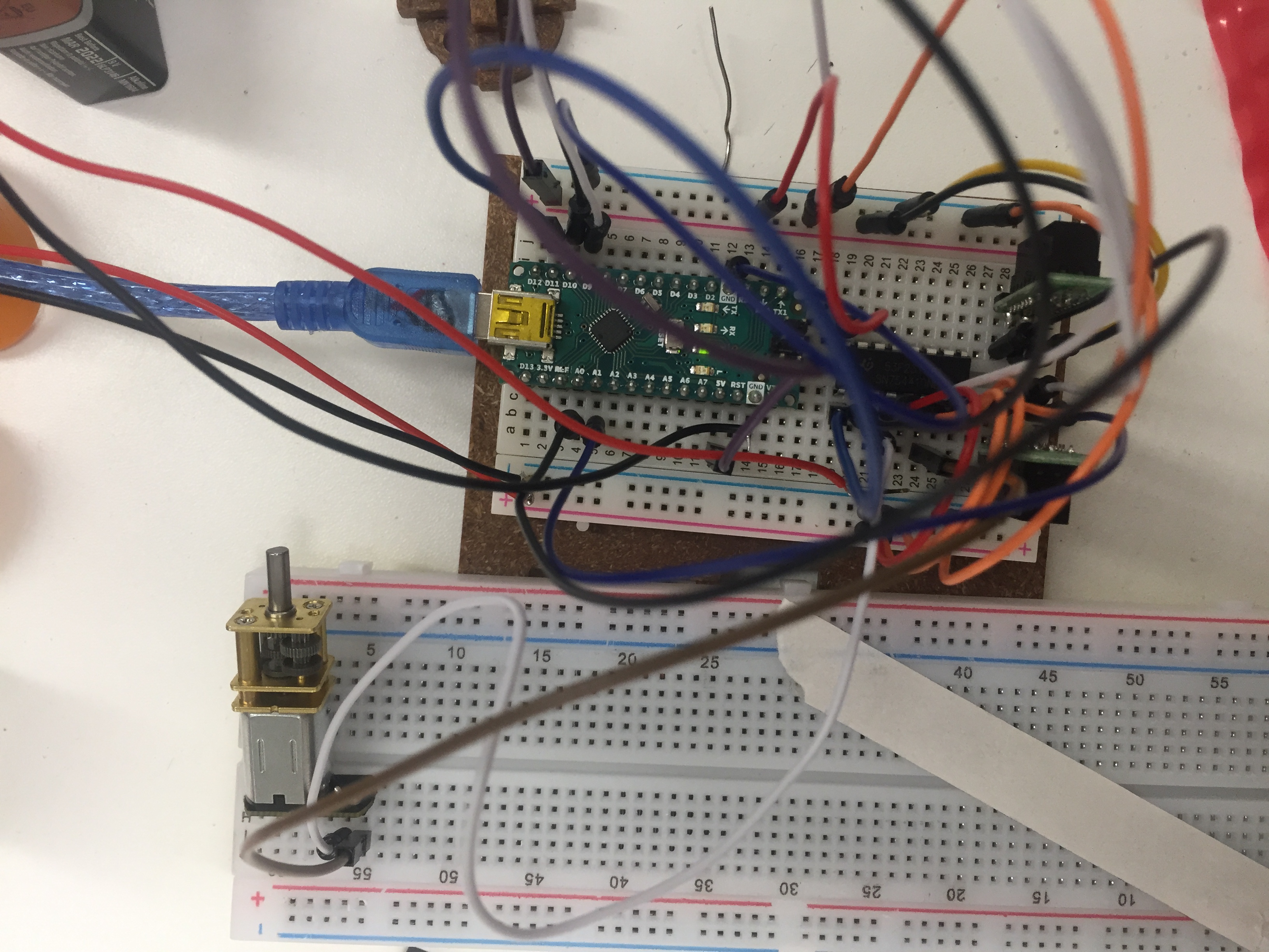
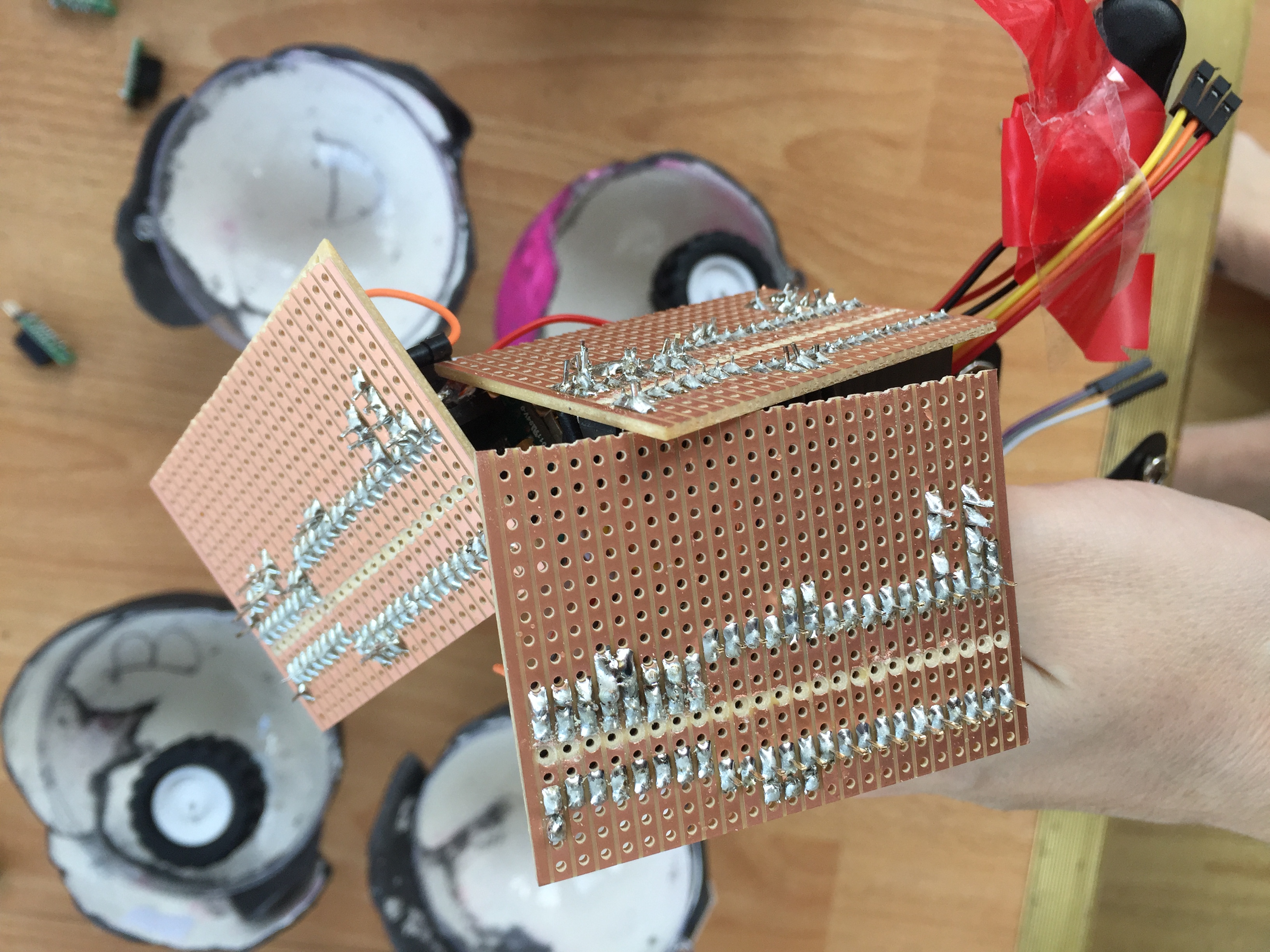
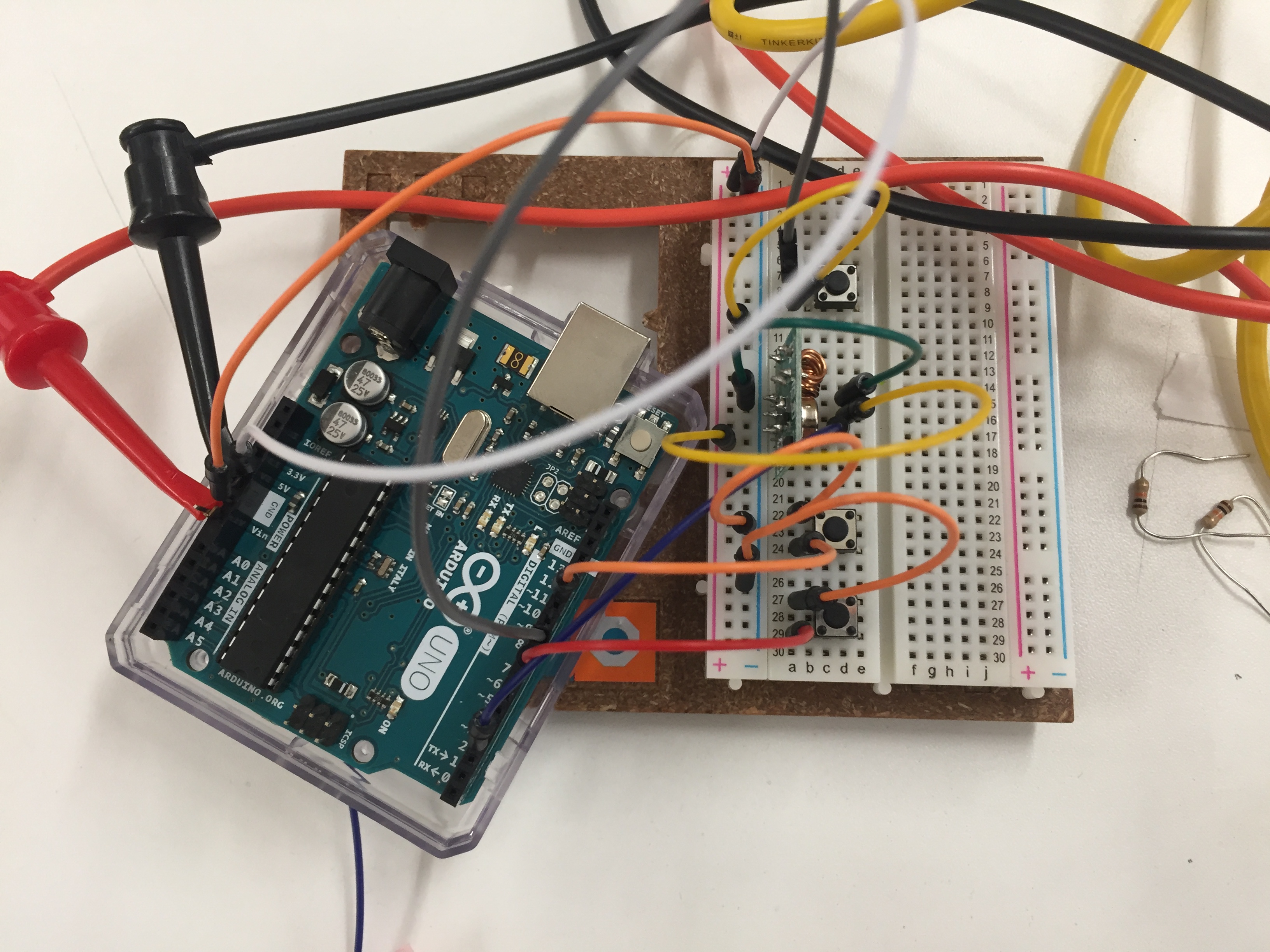
I started with the basic of learning how to control a motor's speed by using analog pins to control the pulse width modulation and change the fluctuations to alter the speed which can be between 0 and 255. I then progressed on to h-bridges as a simple way to flip polarity of the voltage and allow the motor to switch direction by switching the voltage on the two input pins connected to the Arduino and change speed using the PWM h-bridge pin, also connected to the Arduino. I researched h-bridges and selected the L293D h-bridge because it also has a built in diode to protect the circuit from any fluctuations of power back to the Arduino board. My experiments with h-bridges and motor direction and speed are shown in videos and pictures below. I considered using transistors, diodes and resistors to create the same effect, however, this seemed more complicated.
References:
How to control a motor's speed: https://learn.adafruit.com/adafruit-arduino-lesson-13-dc-motors/parts
Motor speed: https://hardwarefun.com/tutorials/controlling-speed-of-dc-motors-using-arduino
H-bridge and motors: https://www.allaboutcircuits.com/projects/control-a-motor-with-an-arduino/
H-bridge information: http://www.me.umn.edu/courses/me2011/arduino/technotes/dcmotors/L293/L293.html
Radio control
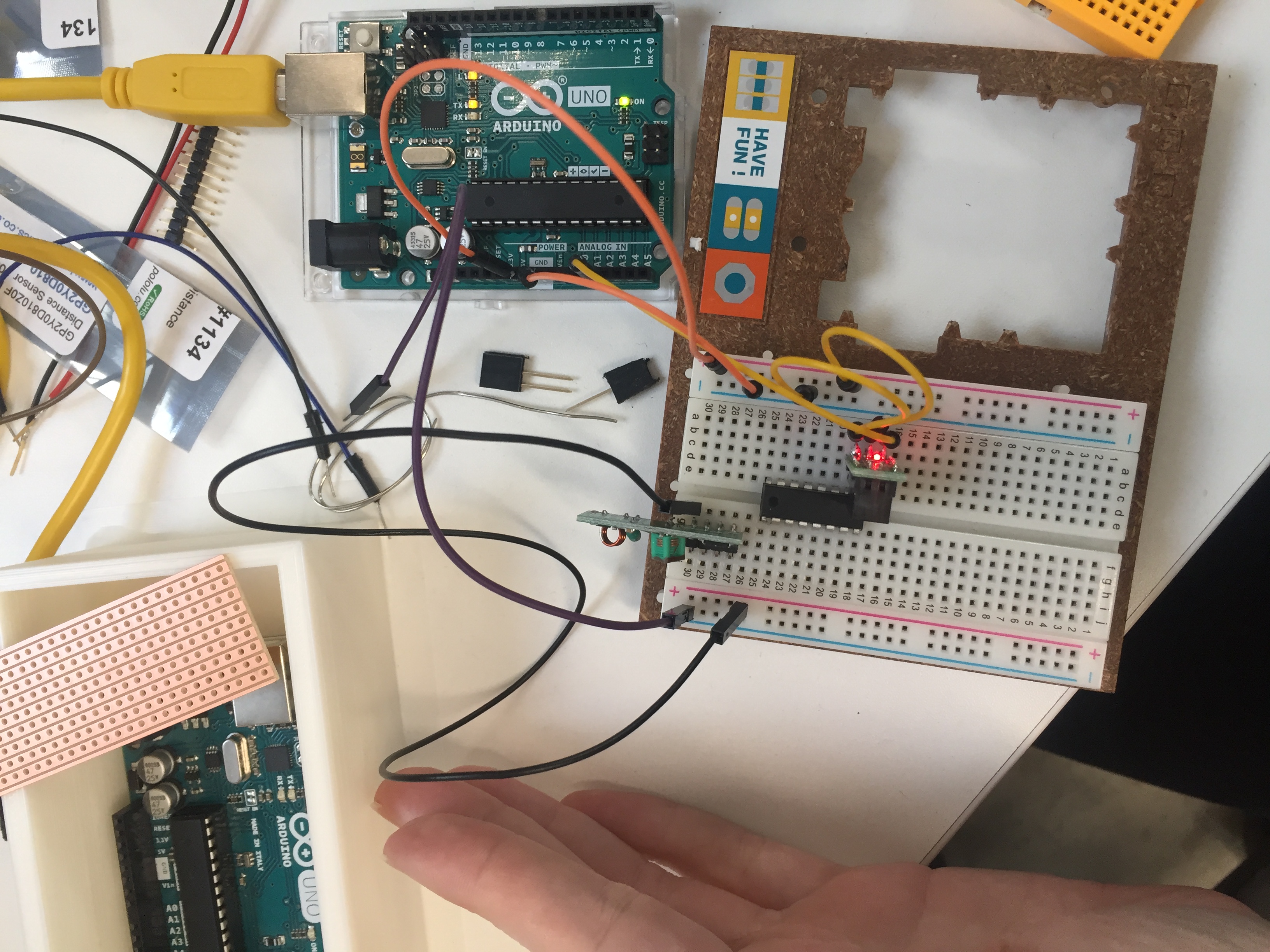
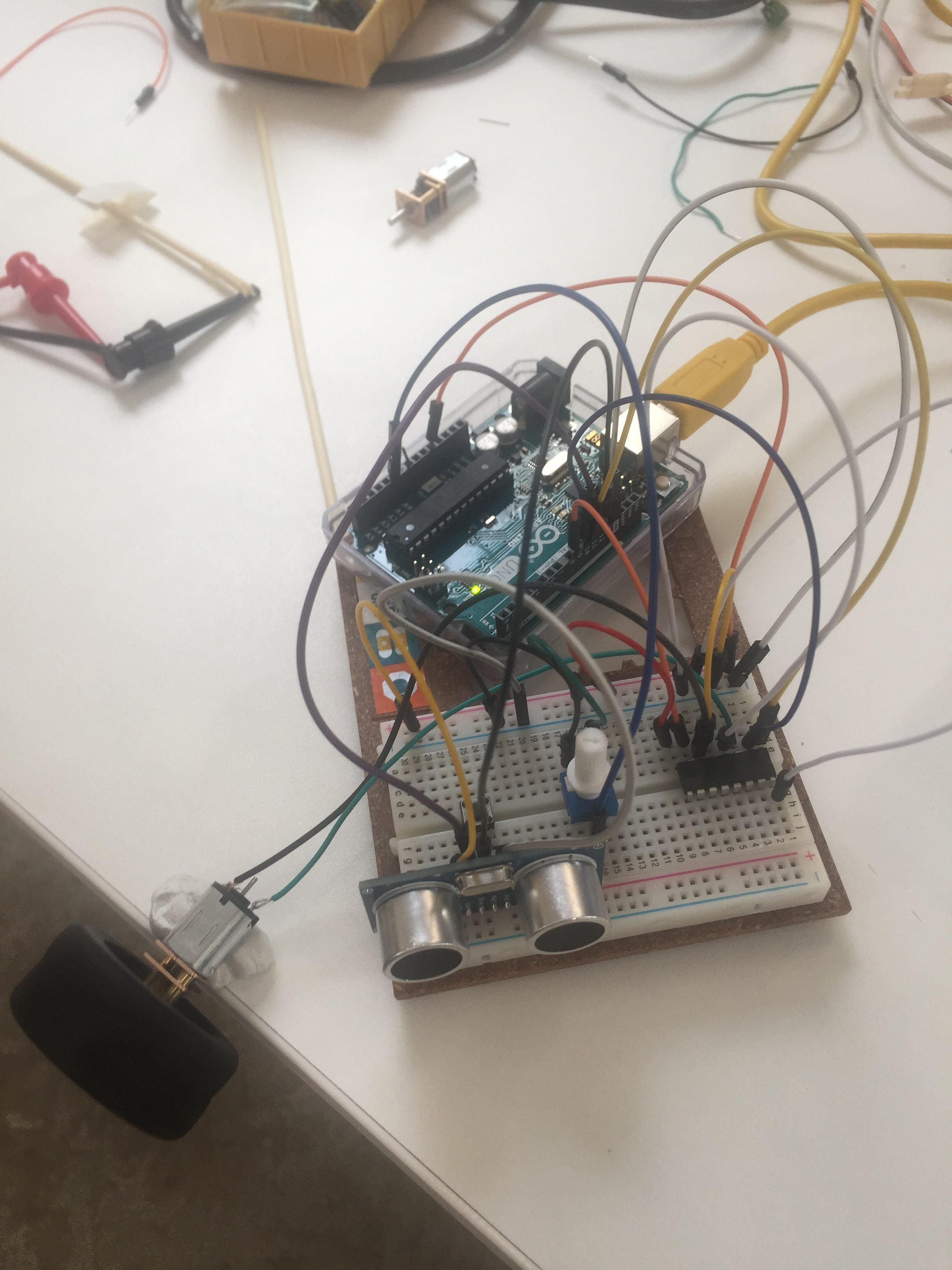
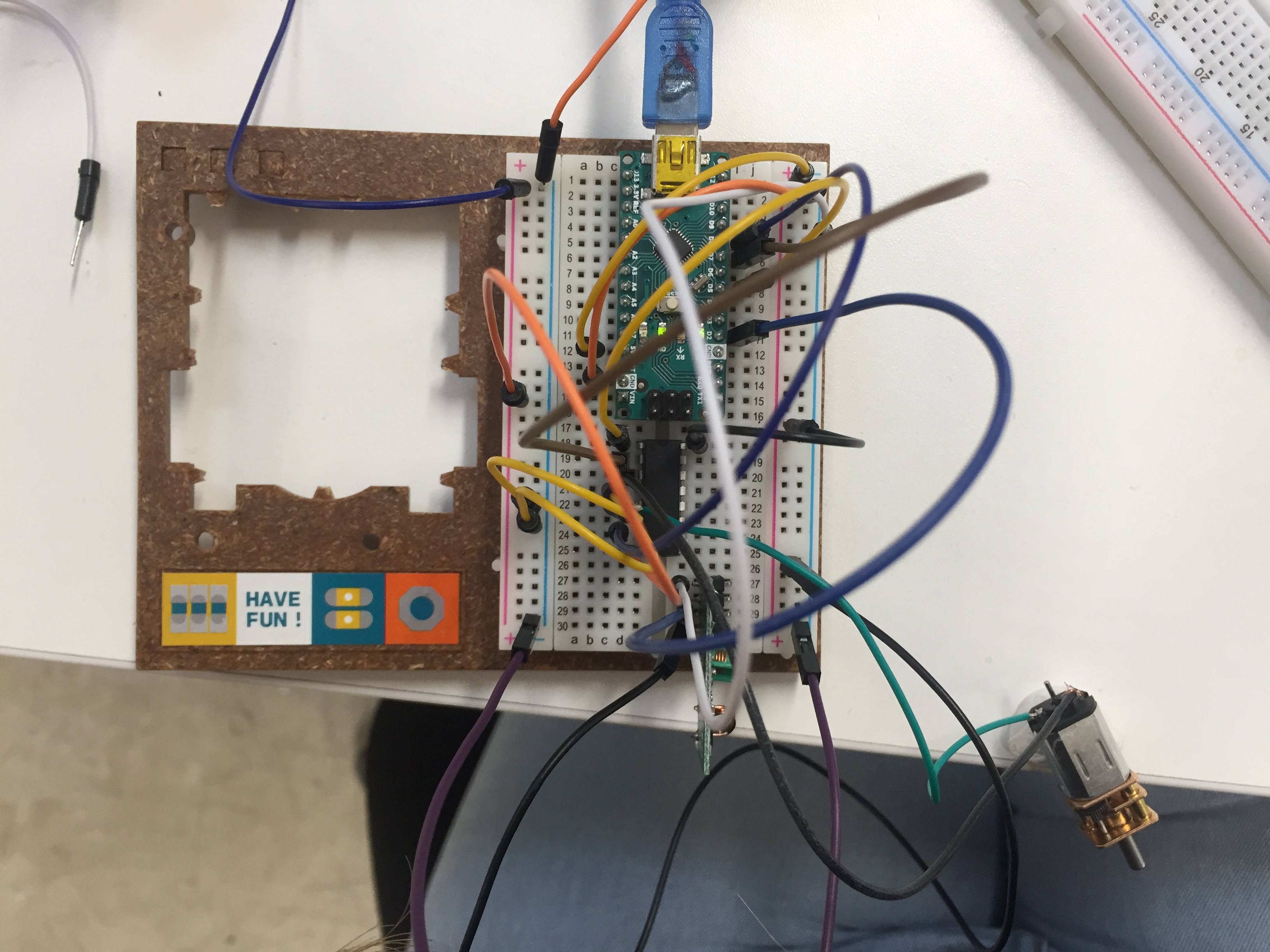
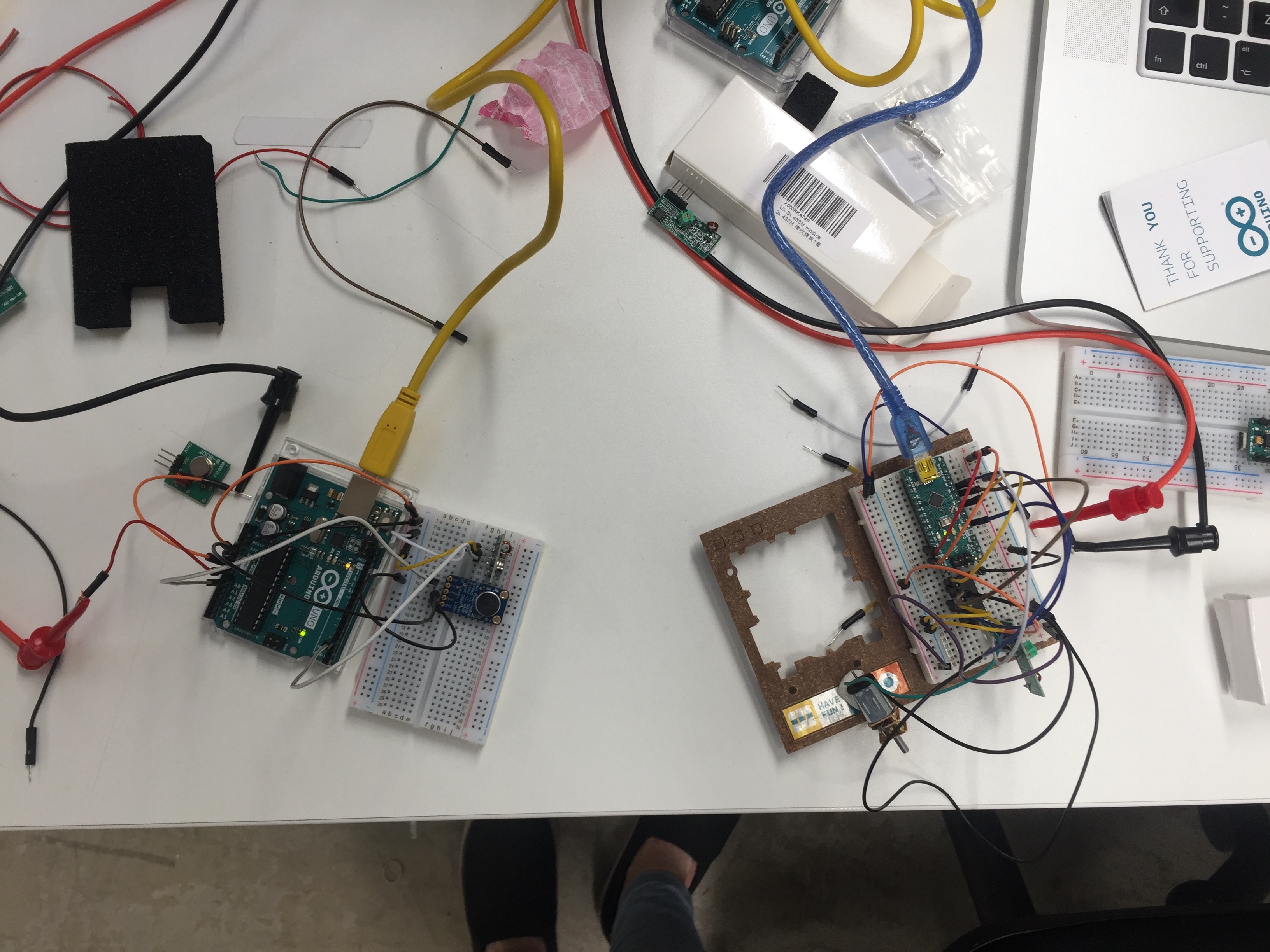
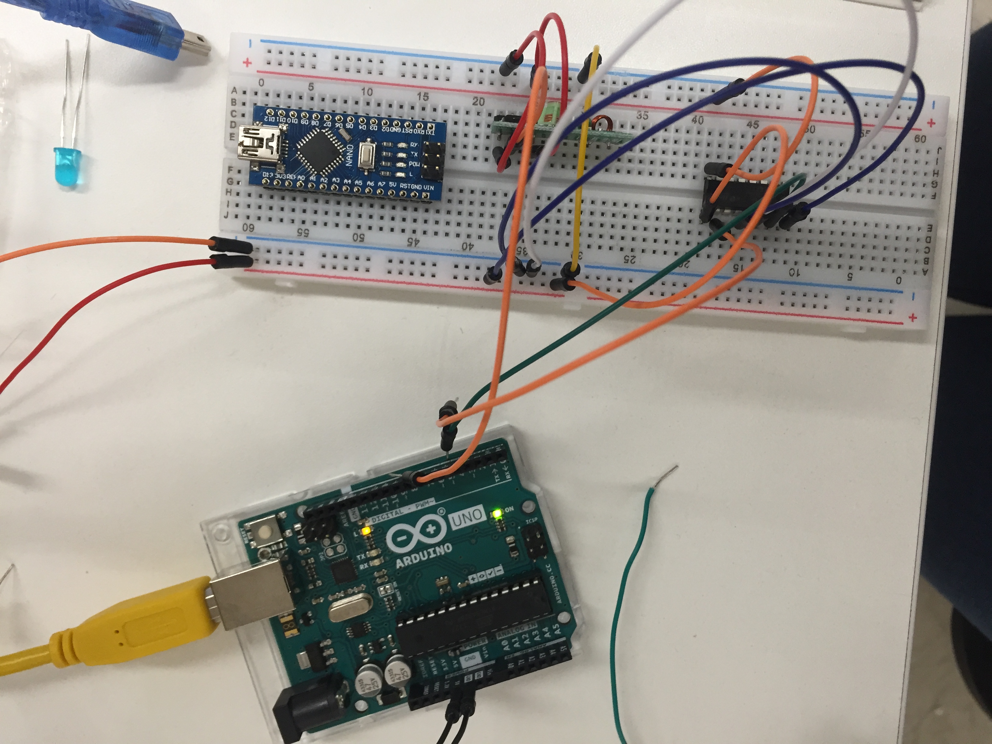
Once I had the basics of motor control understood, I moved on to exploring wireless control of the motor. It rapidly emerged that radio communication was probably the cheapest and potentially the most basic. Initially, I tried basic radio control by making pin 13 on the Arduino blink, and I used basic 433 MHz transistors and receivers to do this as these seem to be the most readily available. I learned also that if a different message is going to be sent to a different robot, that an alternative frequency is needed. When this worked I moved on to exploring VirtualWire and RadioHead libraries for radio control which I understand to be very similar, with RadioHead being the newer one. I kept the commands being sent simple at first.
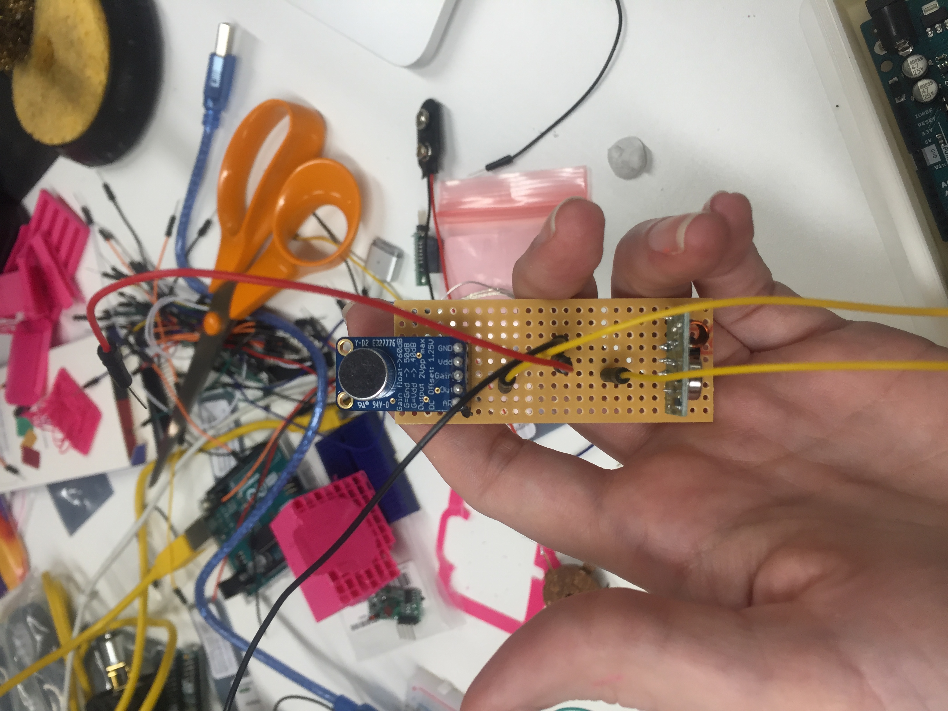
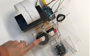
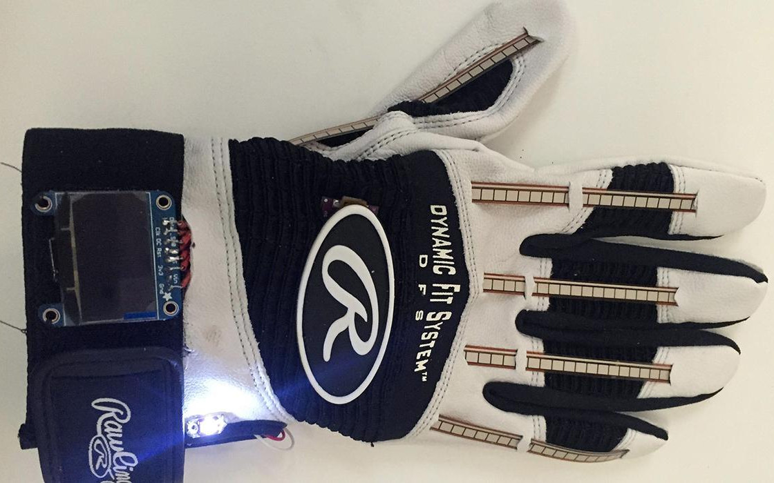
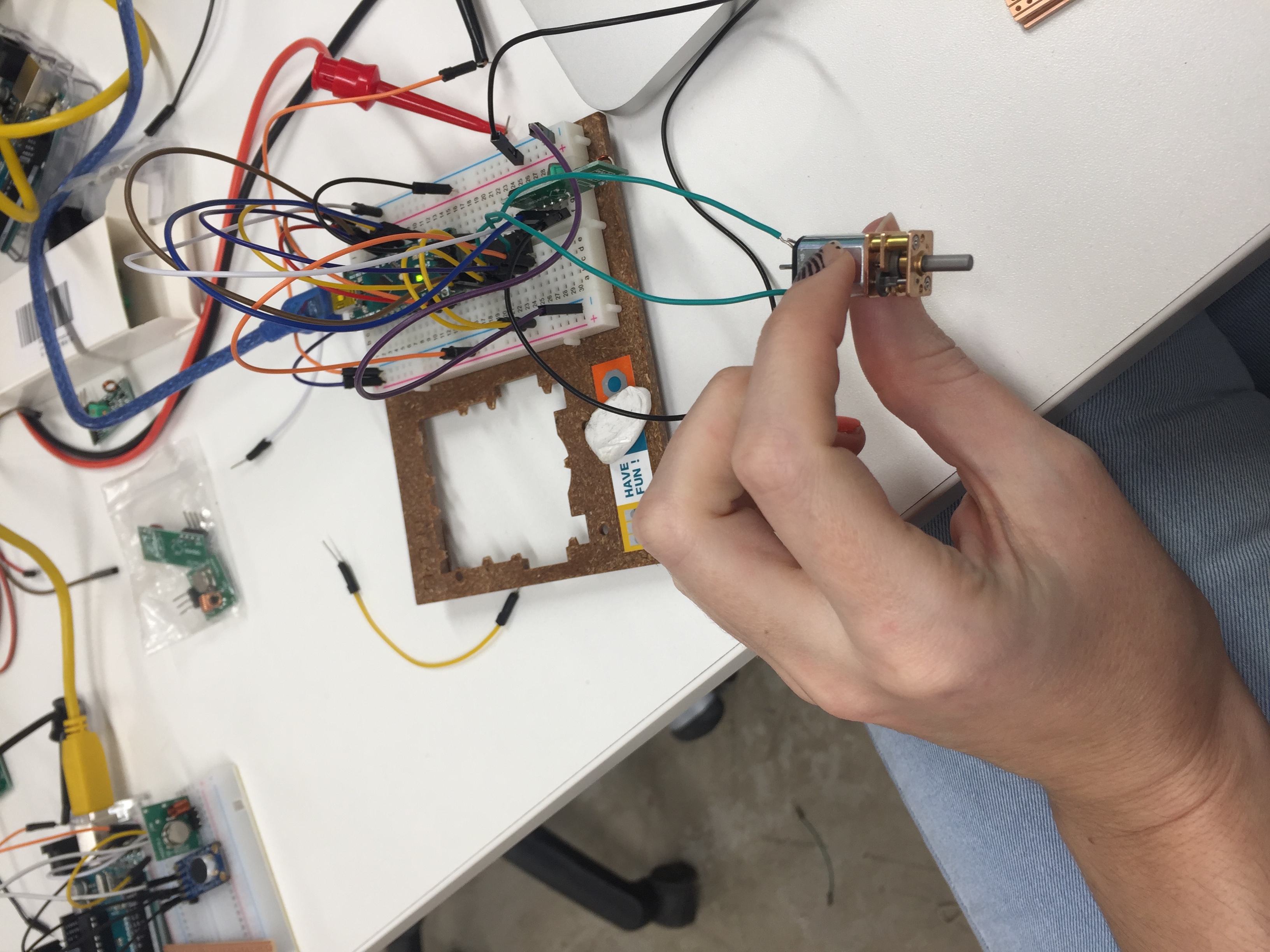
I attached an electric microphone amplifier to a breadboard with the transmitter and when sound levels were above a certain level '1' was sent to the receiver (the robot), to turn the motor on. When sound levels fell below a certain point, '5' was sent to turn the motor off. This worked very nicely and I them moved on to sending streams of information in bytes over the radio communication, however, this was too advanced for the time I had to learn it in the end. This is one area that I will be exploring further so that speed can be moderated in response to external sensors such as sound or other data even.
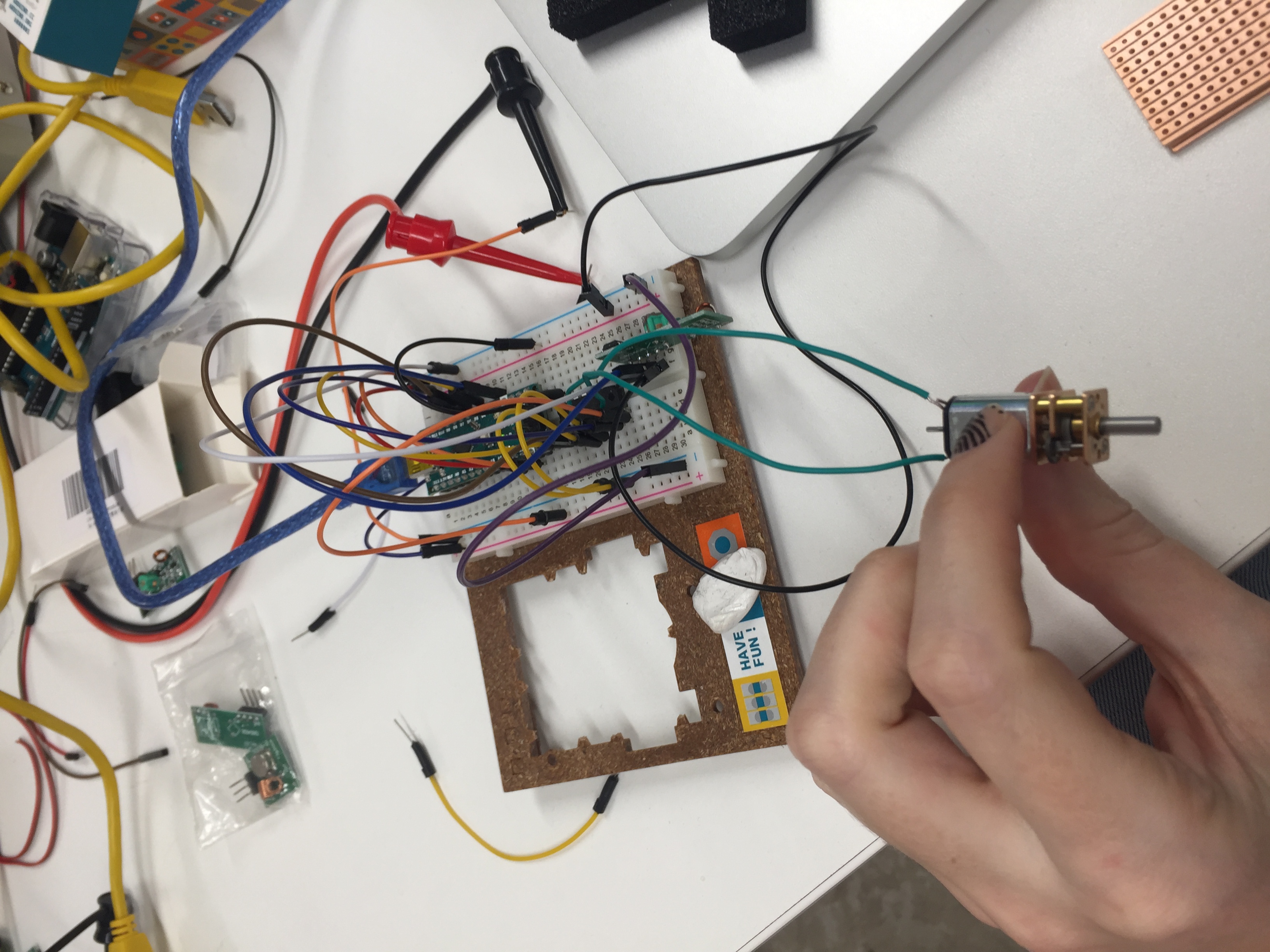
I then proceeded to test using one transmitter to send to several receivers to make sure that this would work, and it did. In order to ensure that the mono robots would move away from objects, I decided on IR digital distance sensors as an uncomplicated was to alert the robot to an object. It works by detecing objects 10cm away, and that is all. It is used as a trigger in my robots. I also set up a boolean reverse so that the robots perpetually in a state of reverse essentially. To stop the robots becoming stuck, however, at 10cm and moving backwards and fowards on the spot, a small timer was put in to allow the robot to move out of the trigger zone.
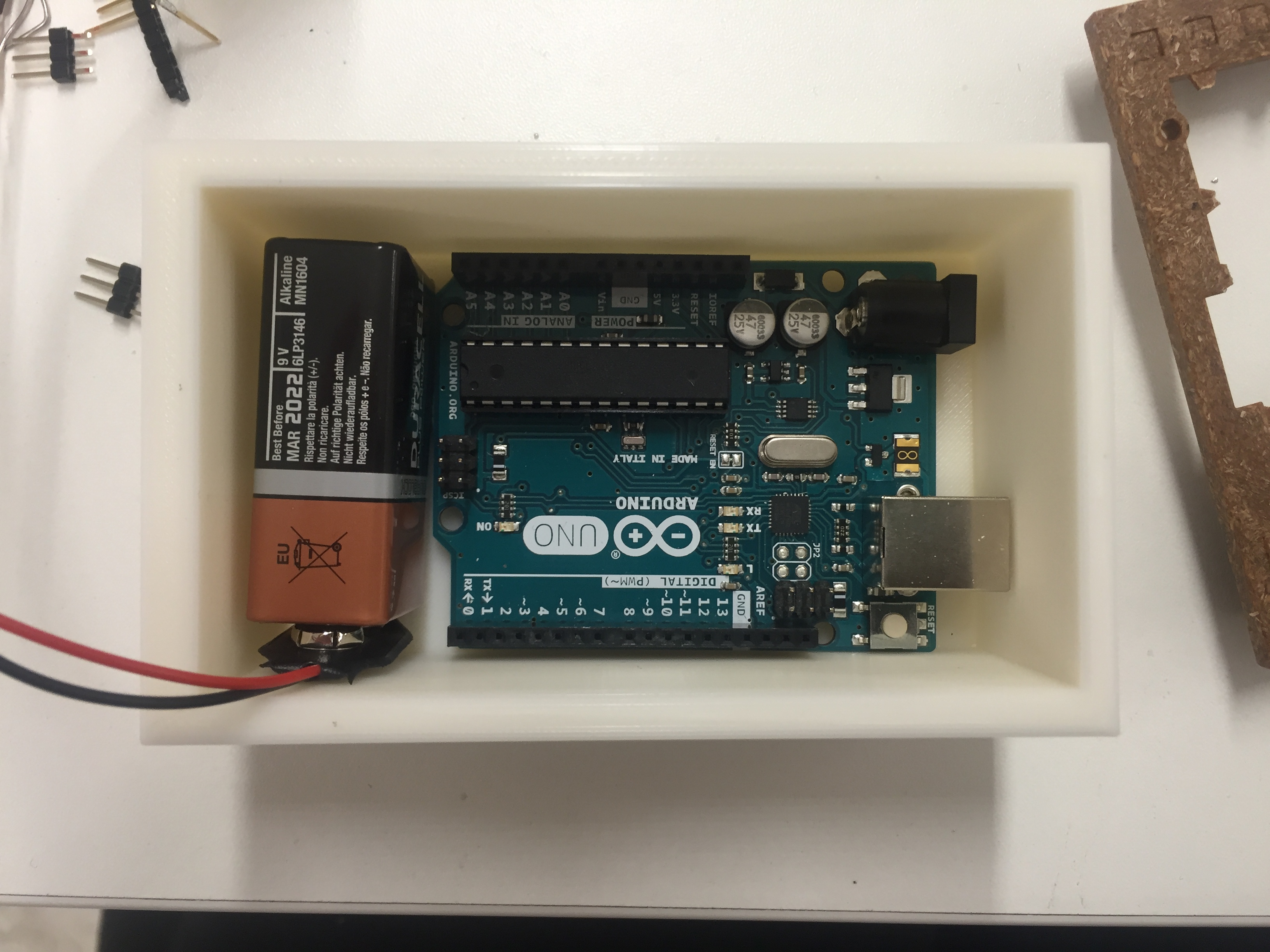
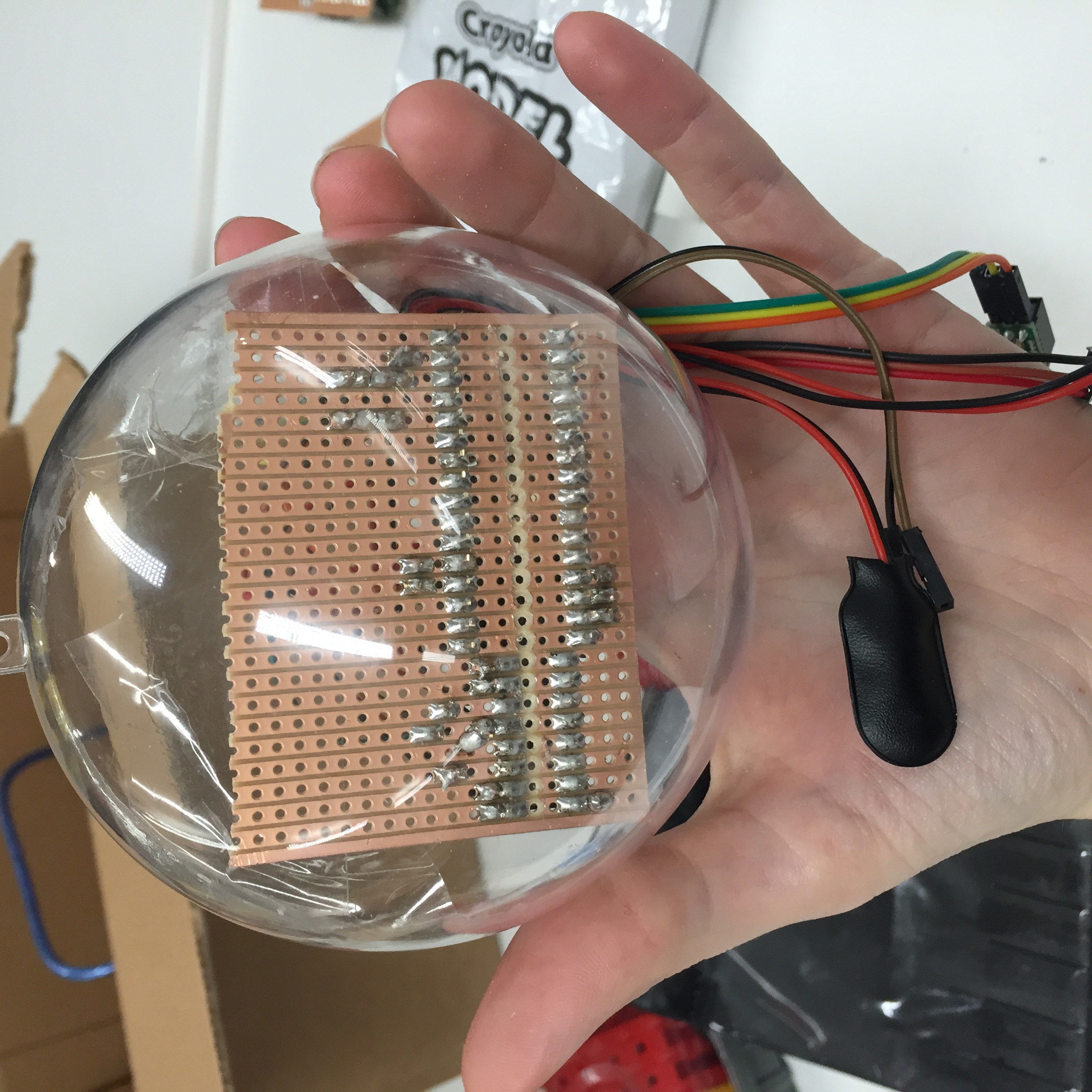
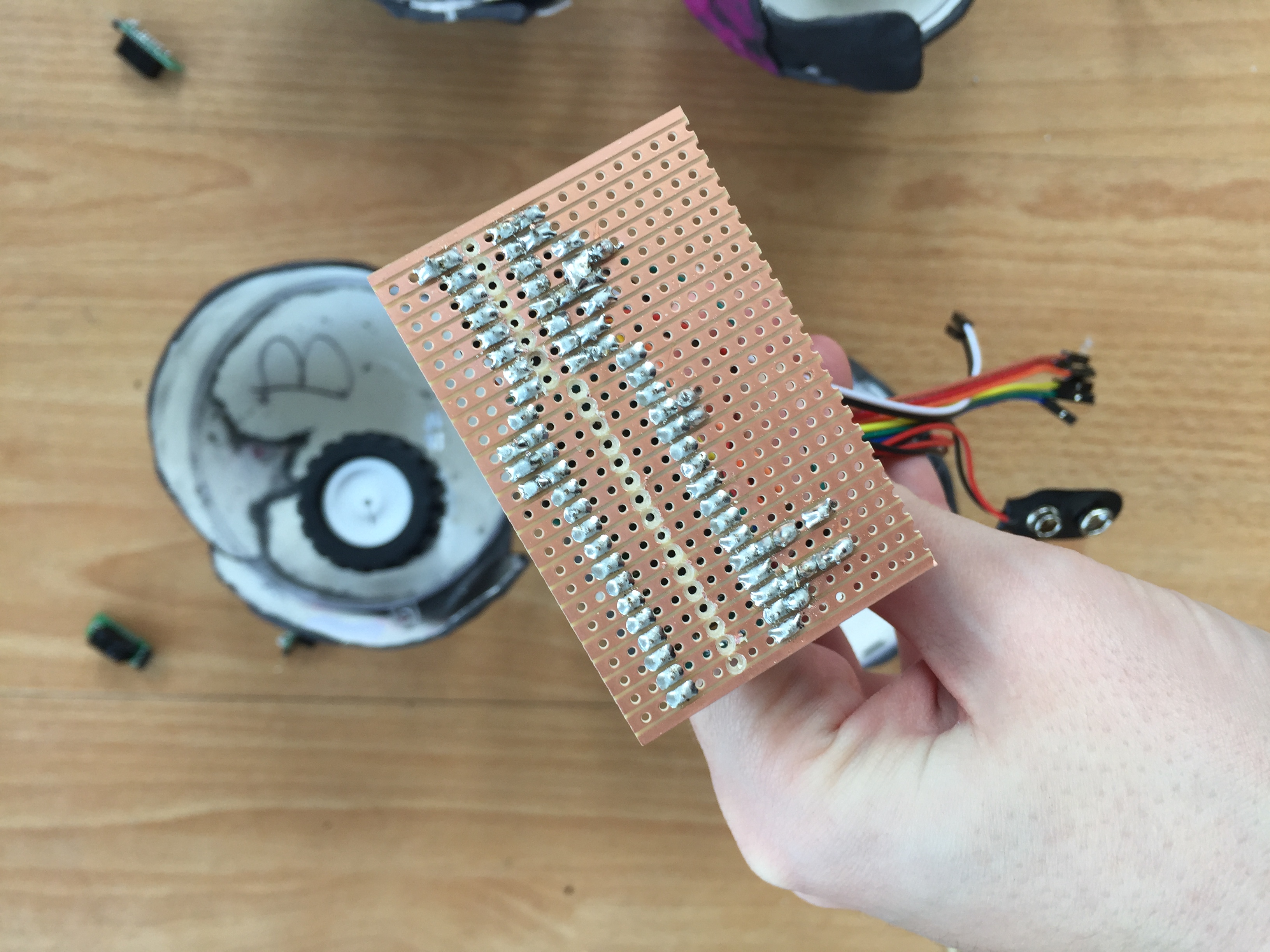
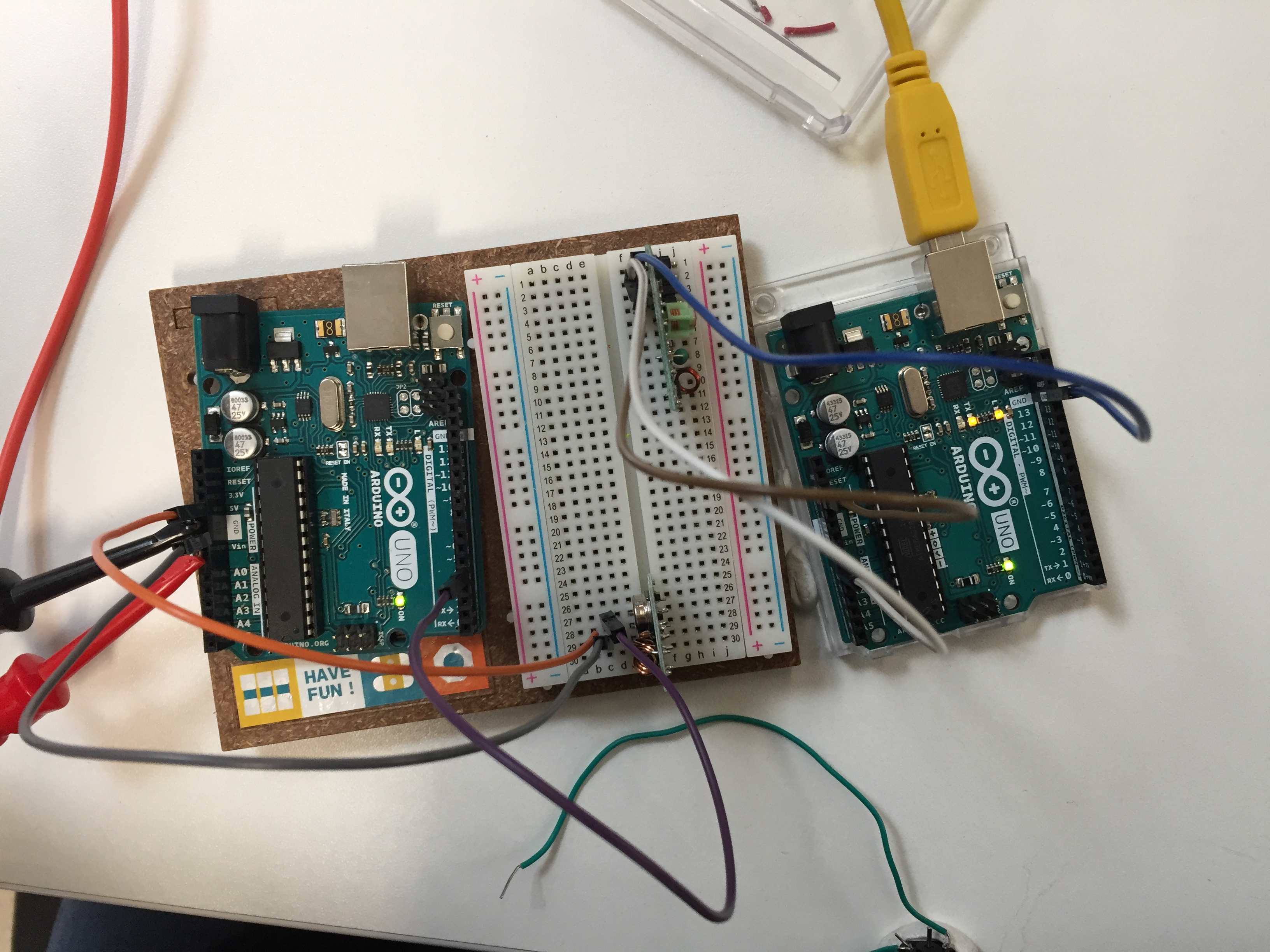
When the whole system of tramsitter and receivers was detached from computer power, the communication ceased. I have worked progressively through this and it may be that sensor pins being used are interfering with communication, given that the radio communication previously did work on external power. I have used only the rx, tx pins on the Arduino and nano, I also looked into whether sensors could be creating magnetic interference with the rado communication and this seems improbable. I also soldered clay capacitors to the positive and negative pins on the motor, as close to the motors as possible, in case there was any interference coming from the motors (though given they had been working previously on external power this seemed also improbable). Clay capacitors were used because the alternative is polarised which would mean the motor direction could not be reversed. I have also considered whether there is some interference form serial communication or whether the USB connection with the laptop is acting as an antenna. I have also soldered antenna on to one receiver to check and this did not work. I will continue to work on this. The fact that the radio communication works when connected to a laptop via USB seems key.
References:
Basic radio blink, no library: https://arduinobasics.blogspot.co.uk/2014/06/433-mhz-rf-module-with-arduino-tutorial.html
Simple radio control: http://www.instructables.com/id/Make-a-Simple-Wireless-RF-Robot-Using-Arduino/
Radio control of robots: http://www.instructables.com/id/Wirelessly-Control-A-Robot-Using-Arduino-and-RF-Mo/
Radio control: http://randomnerdtutorials.com/rf-433mhz-transmitter-receiver-module-with-arduino/
Plans for the robots
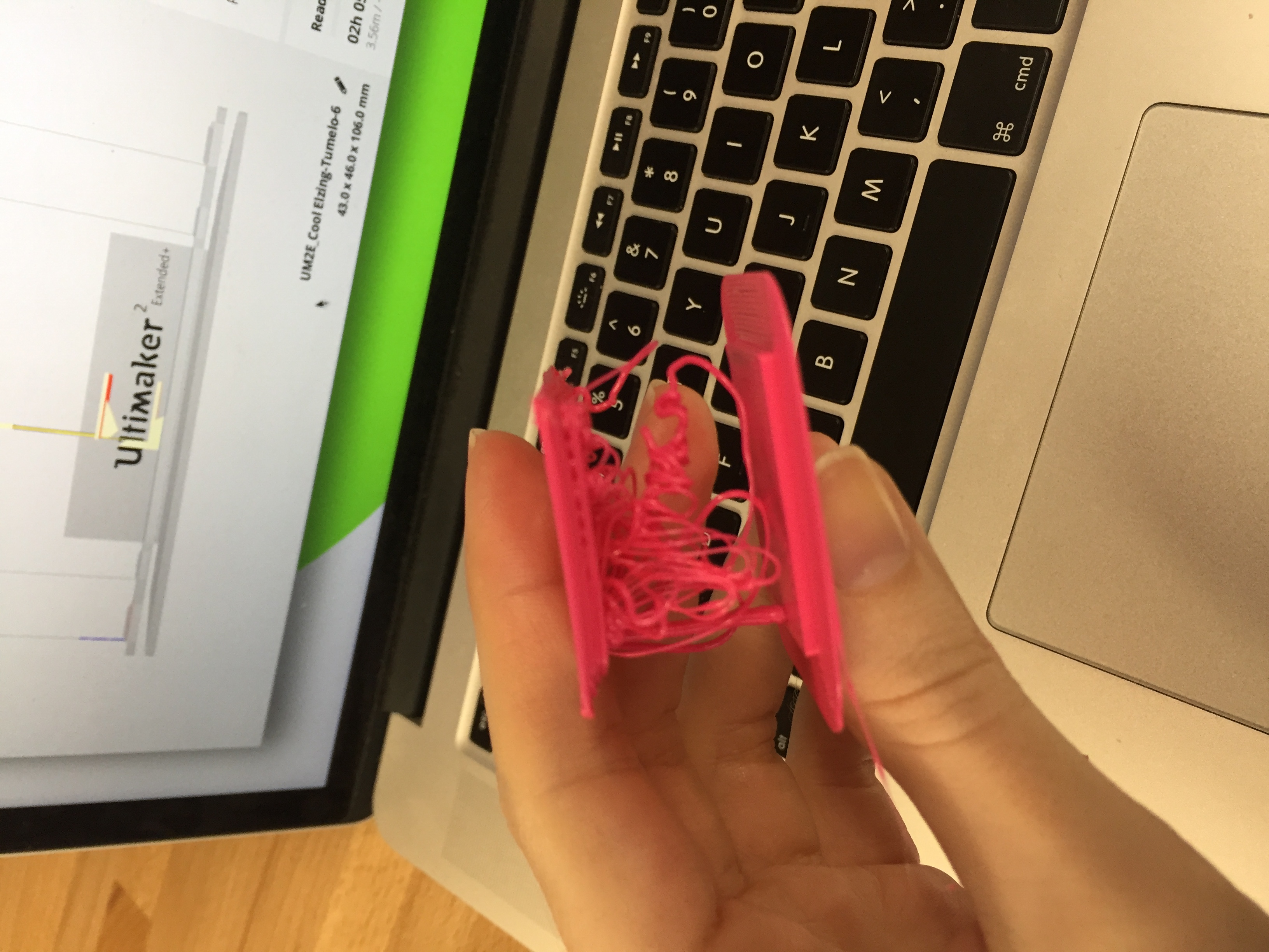
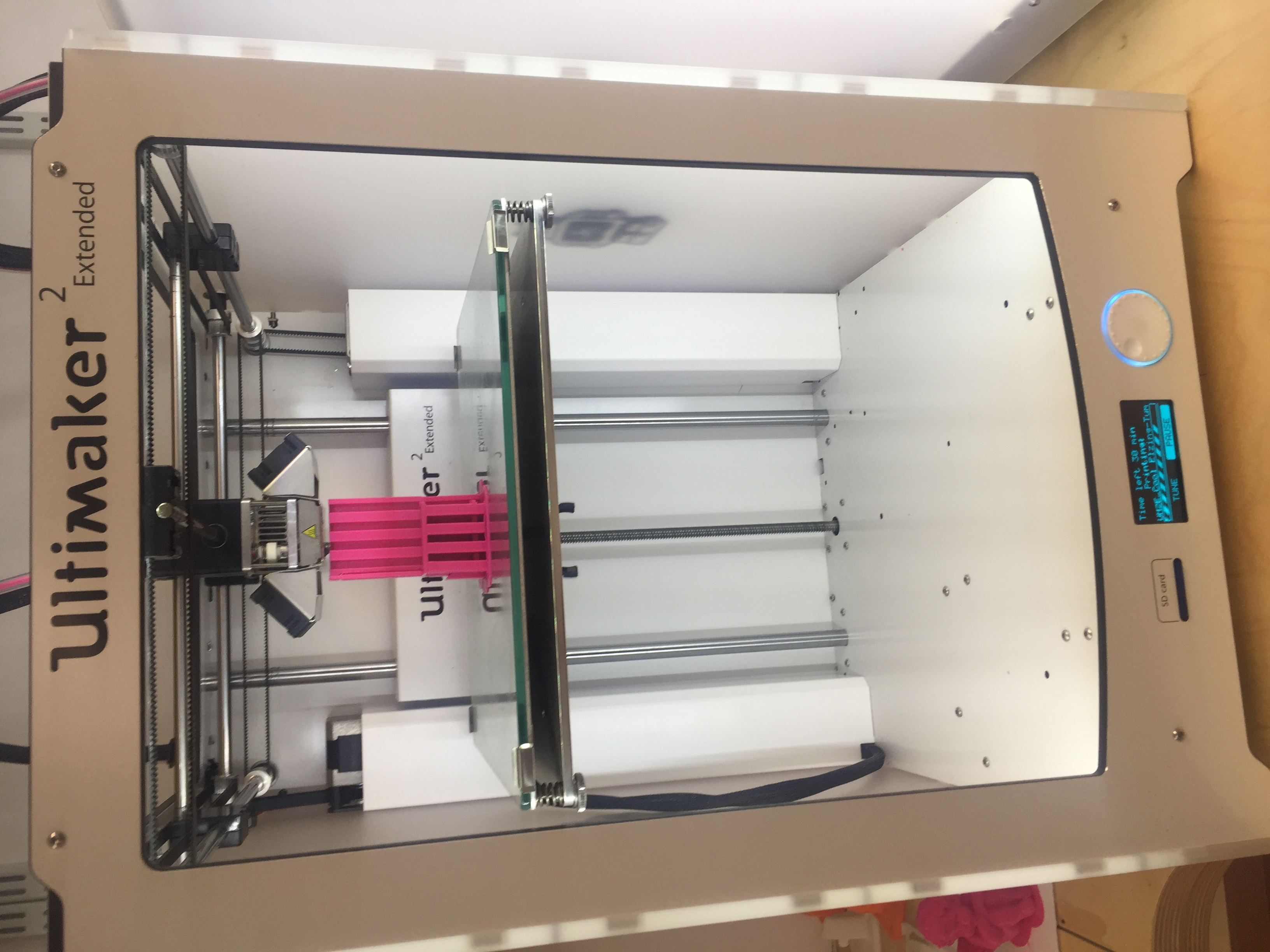
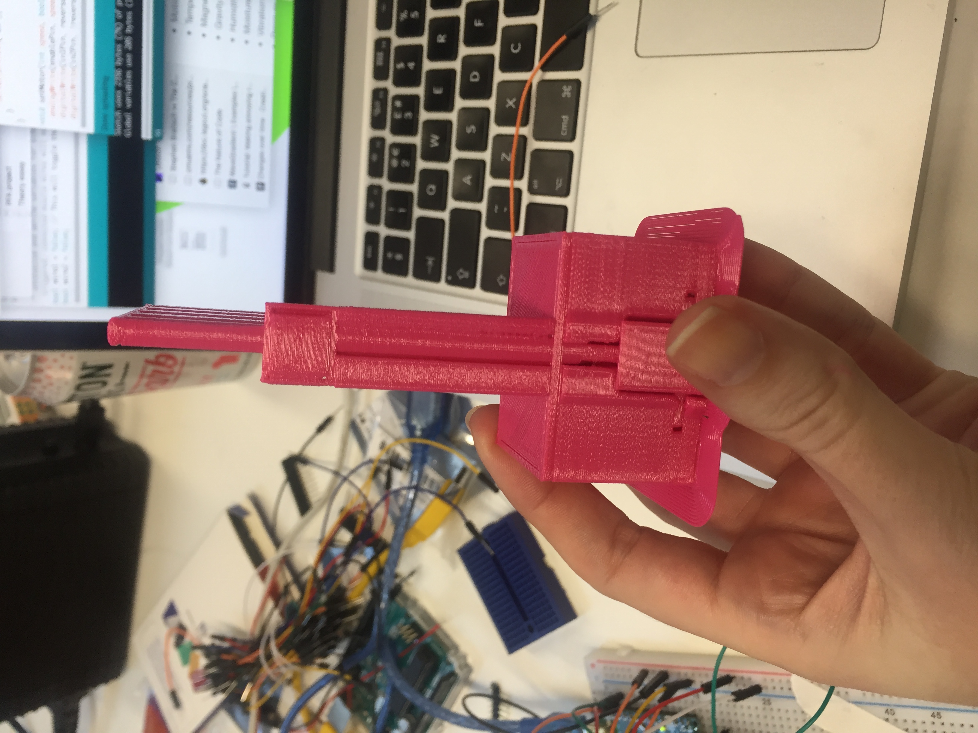
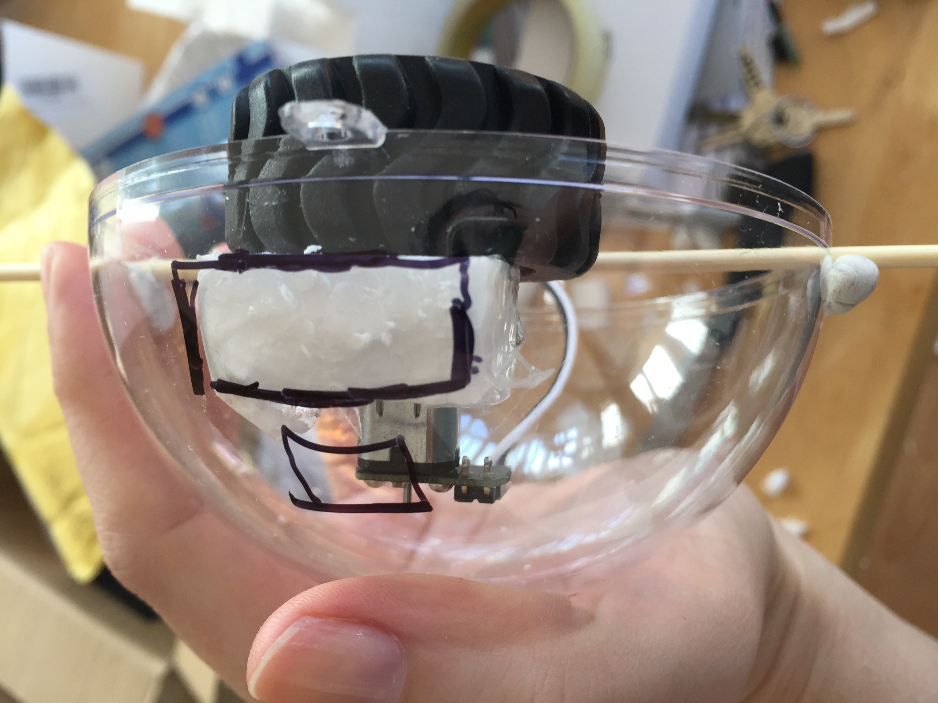
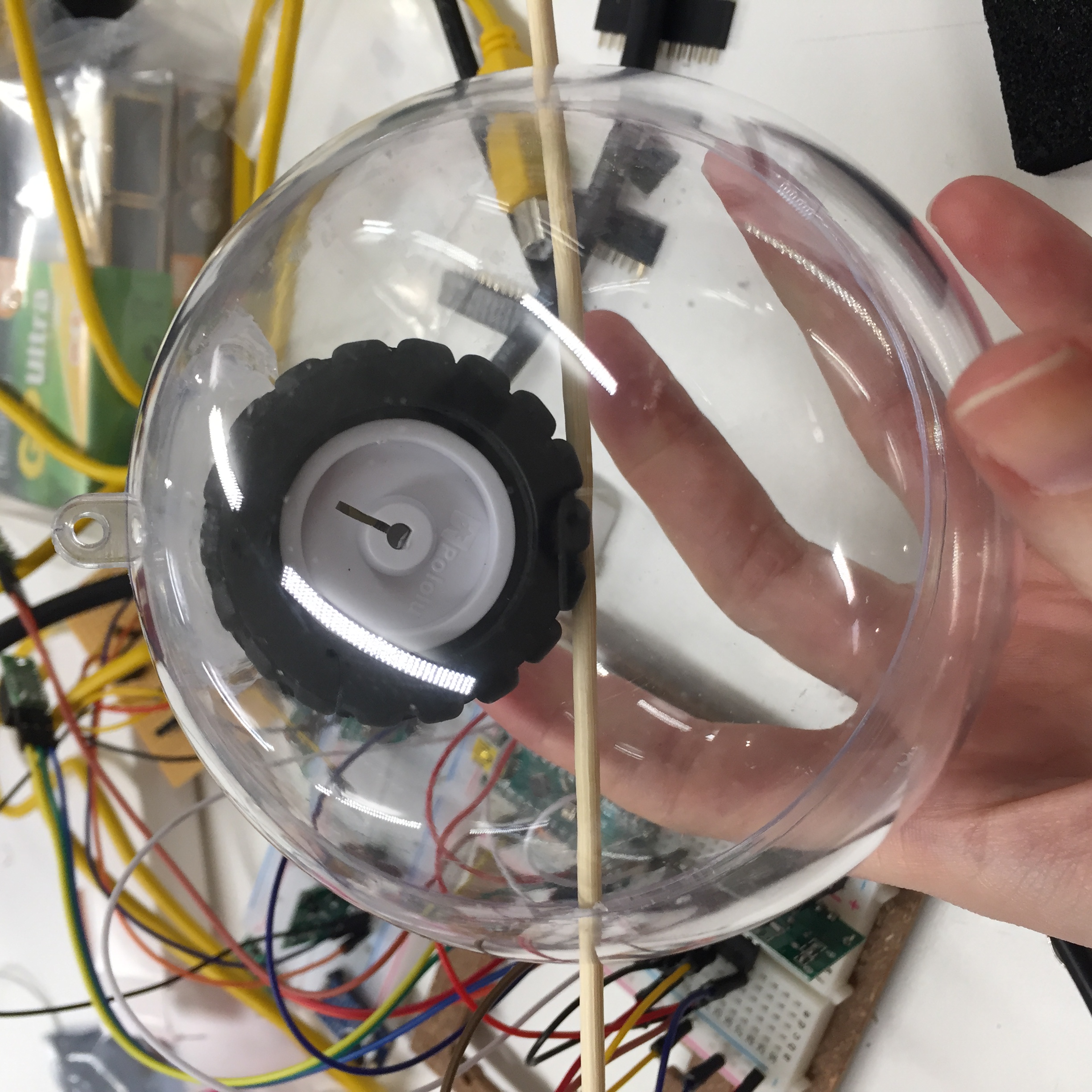
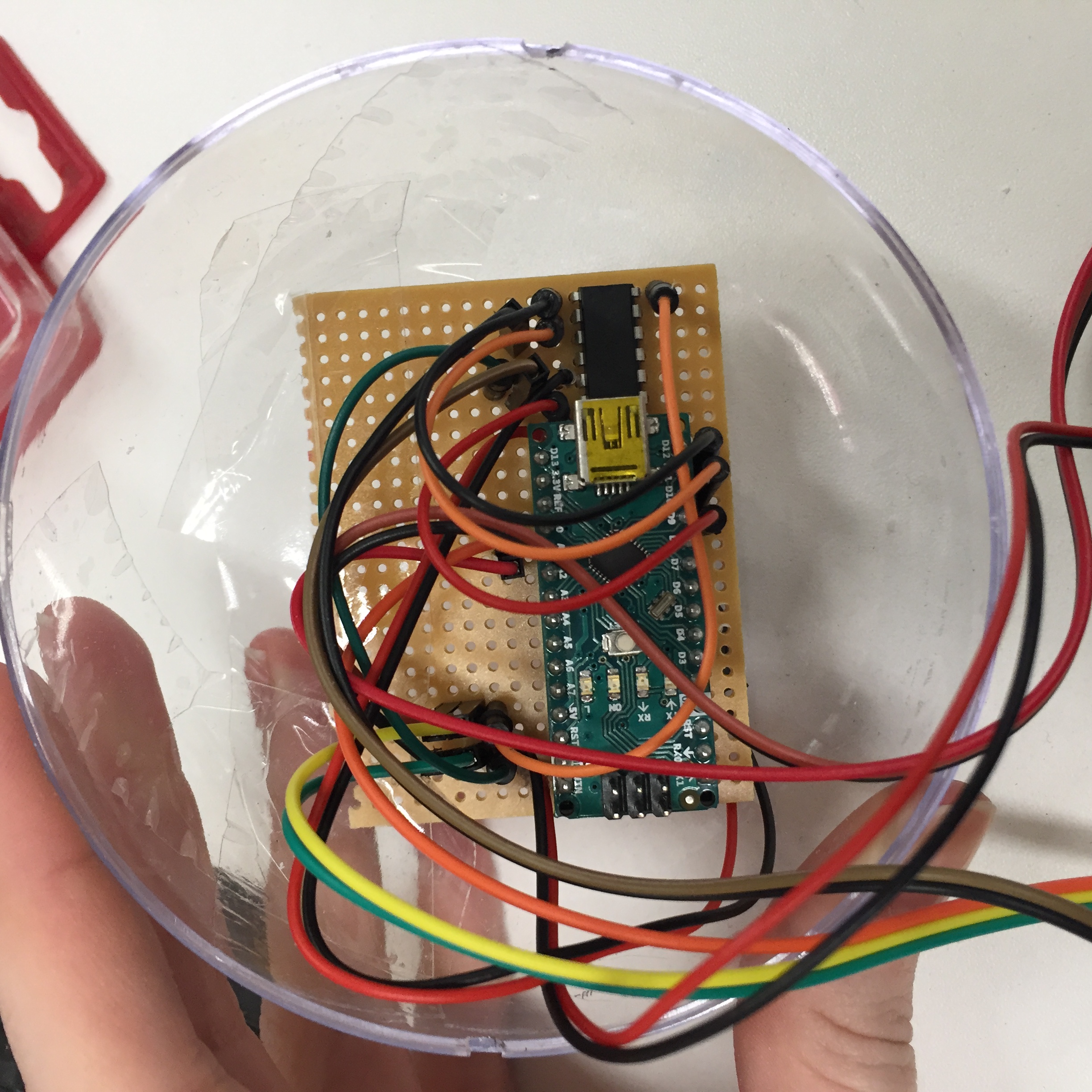
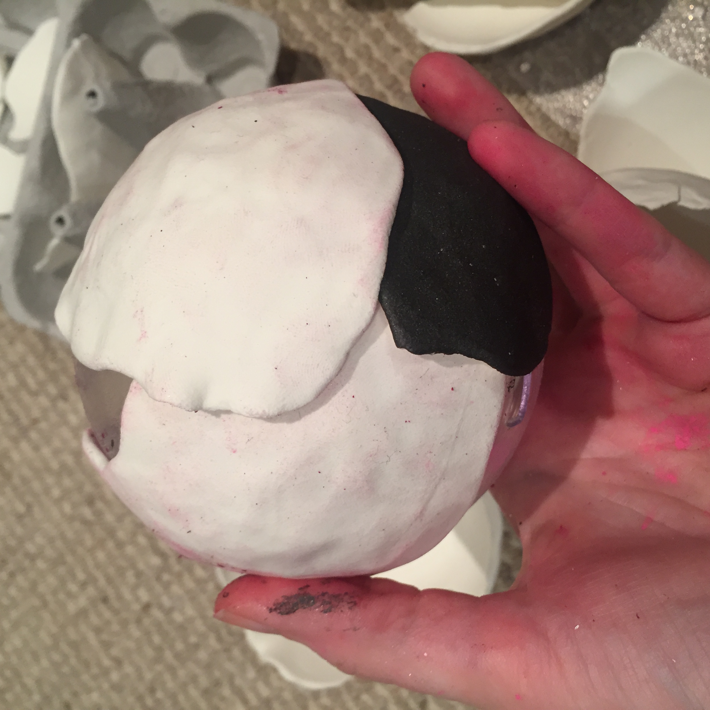
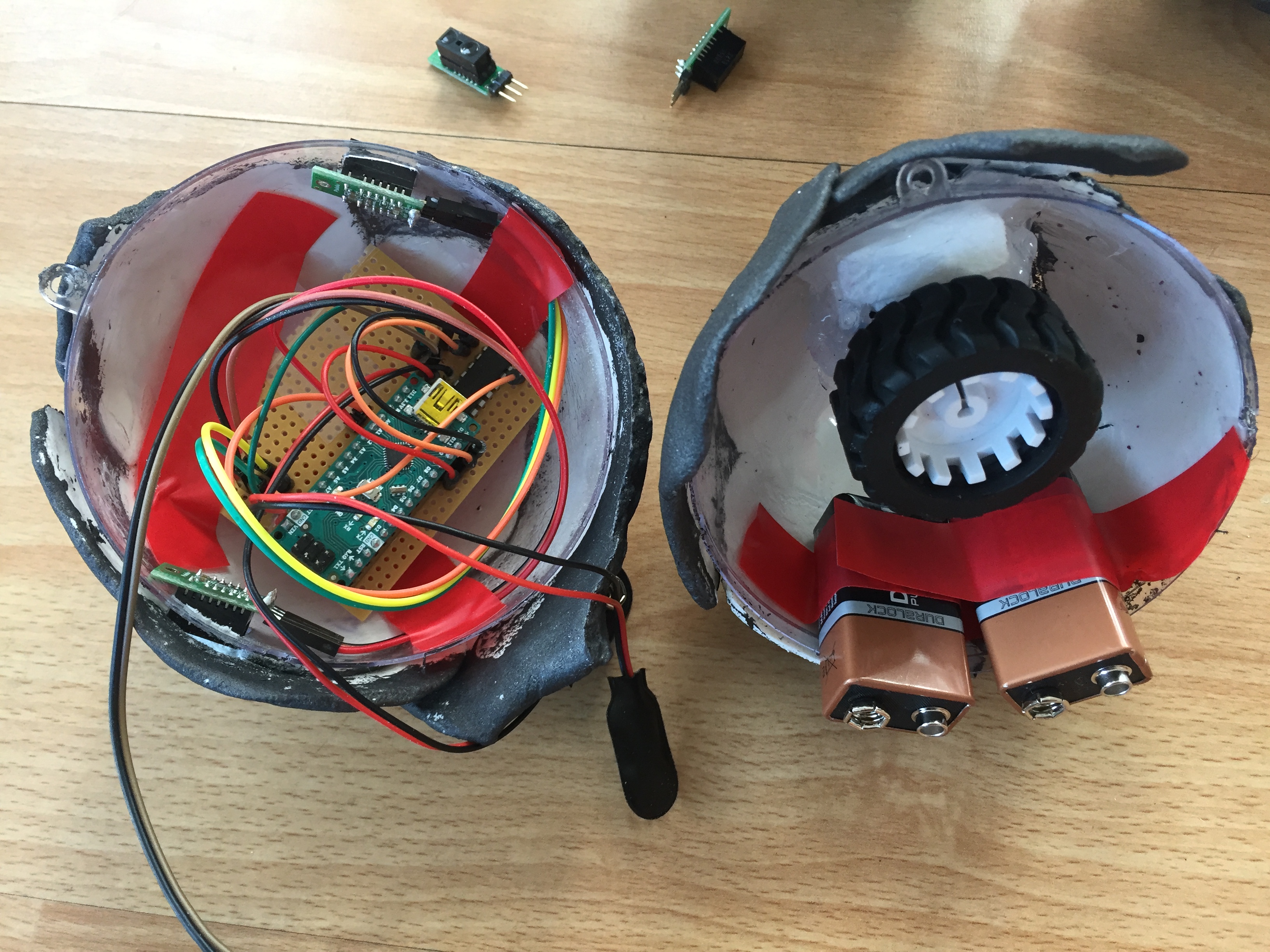
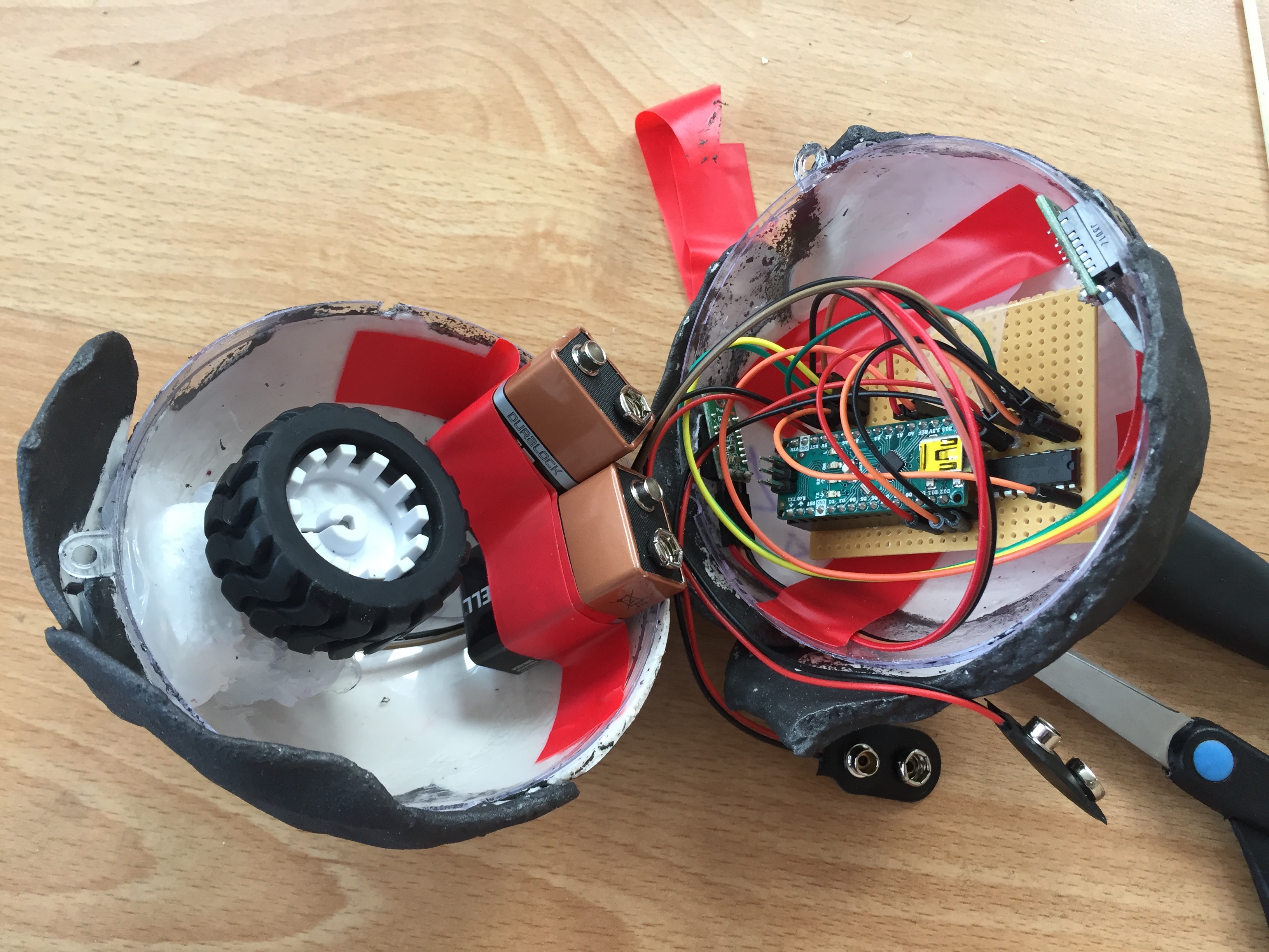
I experimented with 3D printing shapes to go inside the ball shape but I decided that this was actually too slow and complicated for the purposes of this shape (see experiments). Instead I built a compartment to hold the wheel out of styrofoam and glued it in using silicone glue, which works quite well for temporary purposes. It would be good to build that compartment using 3D printing to make it more secure, as the wheel is definitely the most important part of these robots. If the wheel is secure the robots can even climb vertically. It would be good too to have a permanent separation for the circuit from the wheel movement. It is the wires that have cause the most problems with the movement of the robots as they can get caught in wheels. The wires also need to be much more precise and concise for future versions, any excess wire in the small ball shapes is an interference potentially.
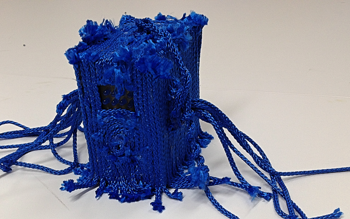
I have many ideas for these. Feeding in dynamic data to alter speed and behaviour in more complicated ways is one direction. Having much faster robot forms hidden in tubes of material that billow up when they race through the tube is another idea. Kinetic sculptures is another area based on toys. I like the simplicity of kinetics and the complexity. I have seen toys (I think I also used to play with some) where a ball or toy person bounces up between two pieces of wood due to a sideways motion. It could be very interesting and complicated to bouce a shape up with more electronic means than a hand. I like the way the robots interact with each other (and with hands) and that could also be useful to explore further. I want to refine these shapes much more. They have been extremely problematic and also very satisfying (and frustrating!).