


Touching Light
A tactile drawing tool that links texture and light; a projector with exposed mechanics and capacitive copper inputs.
produced by: Rebecca Aston
Concept
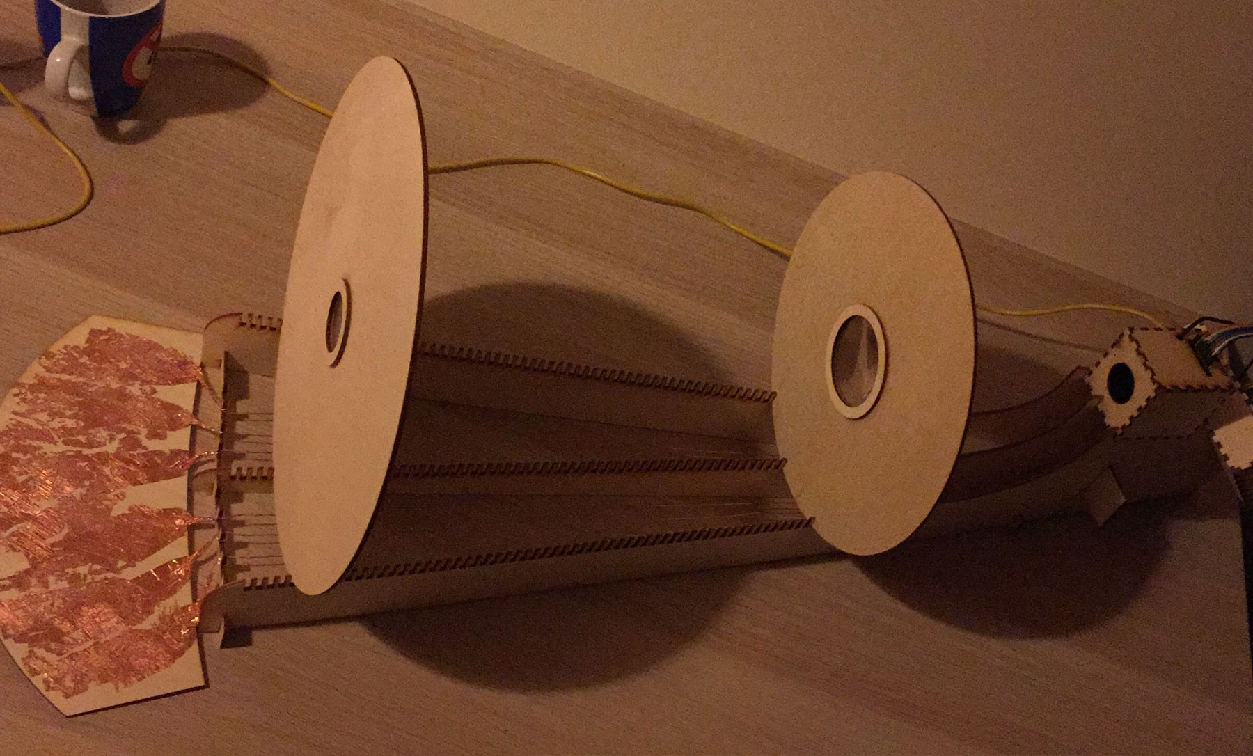
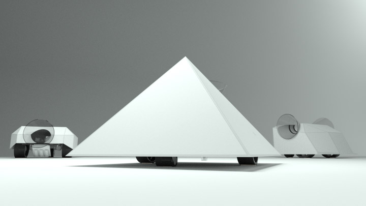
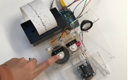
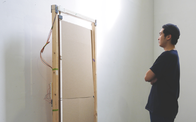
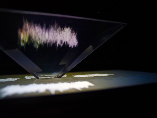
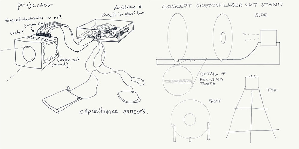
My concept was to create a projector that exposed the mechanics of how a projector works in combination with capacitance input. I settled on a structure that alluded to a diagrammatic cone of light.
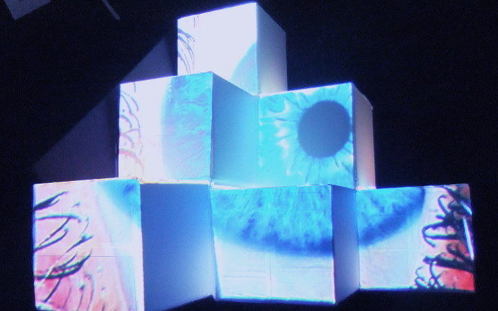
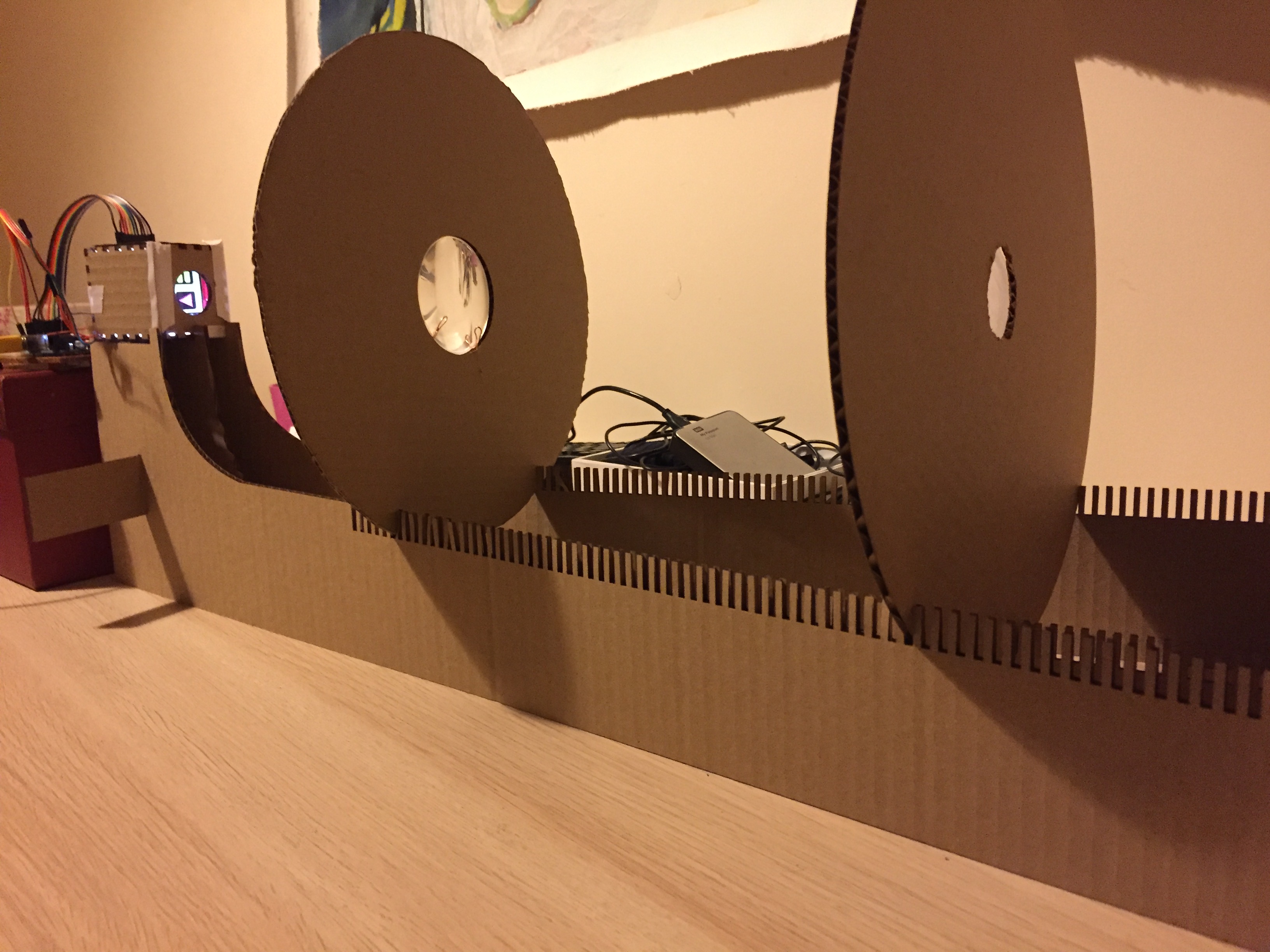
The base of the projector angles out from the projector box, where an LED panel shines light through a small LCD screen. The teeth on the base of the projector serve as a focusing mechanism; the two round panels can be moved along the teeth to adjust the size and sharpness of the projected image. The first round panel has a magnifying lens embedded in it which projects the light and flips the image from the projector box onto the second panel which serves as a projection surface with a piece of semi-transparent acrylic. The six capacitive copper surfaces on a panel of wood are placed in front of the projection surface; copper wire is strung up the center of the projector base to the Arduino.
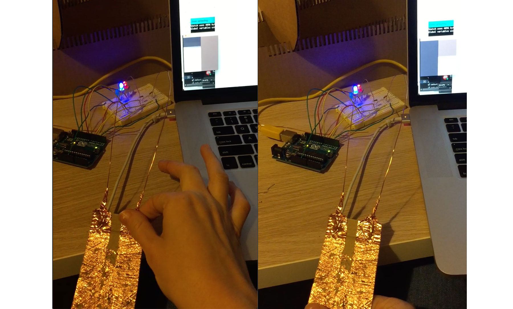
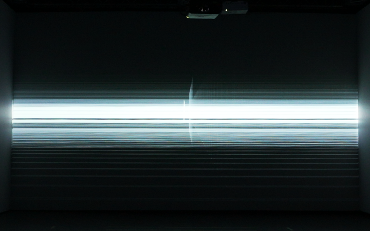
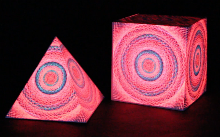
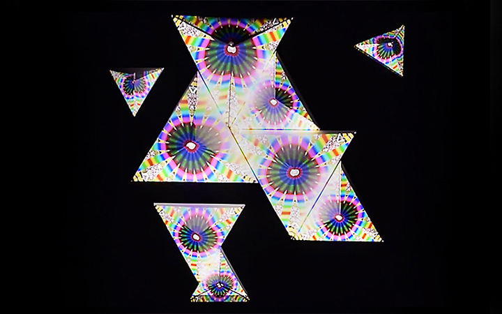
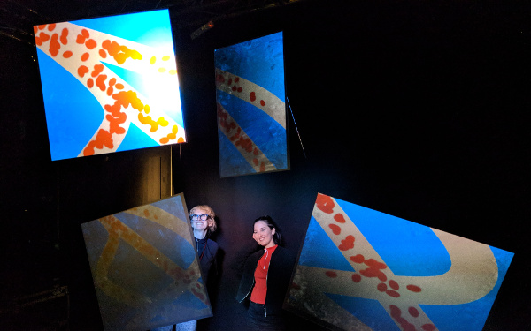
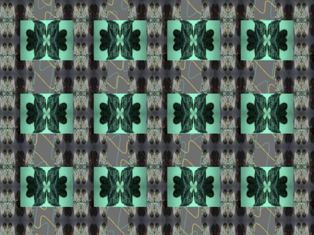
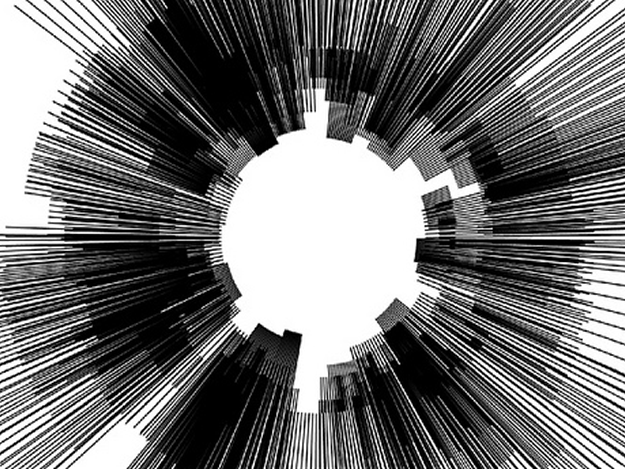
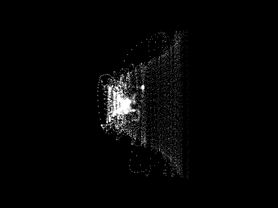
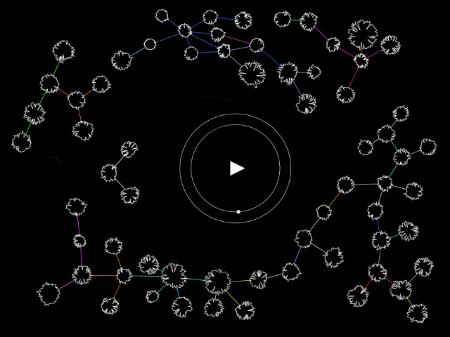
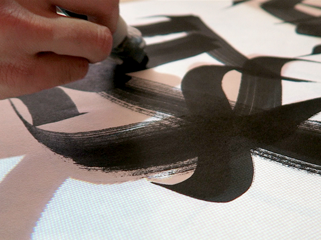
Touching the textured copper draws shapes and colors to the LCD screen. In the final sketch, each of the six sensors was represented by a different color, a triangle radiating from the center was drawn whenever the sensor was registering capacitance over a certain threshold. In addition circles radiated out of the center; the number and position of the circles depending on how high the capacitance is. The shapes are additively layered over each other to create a drawing.
Process and References
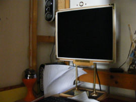
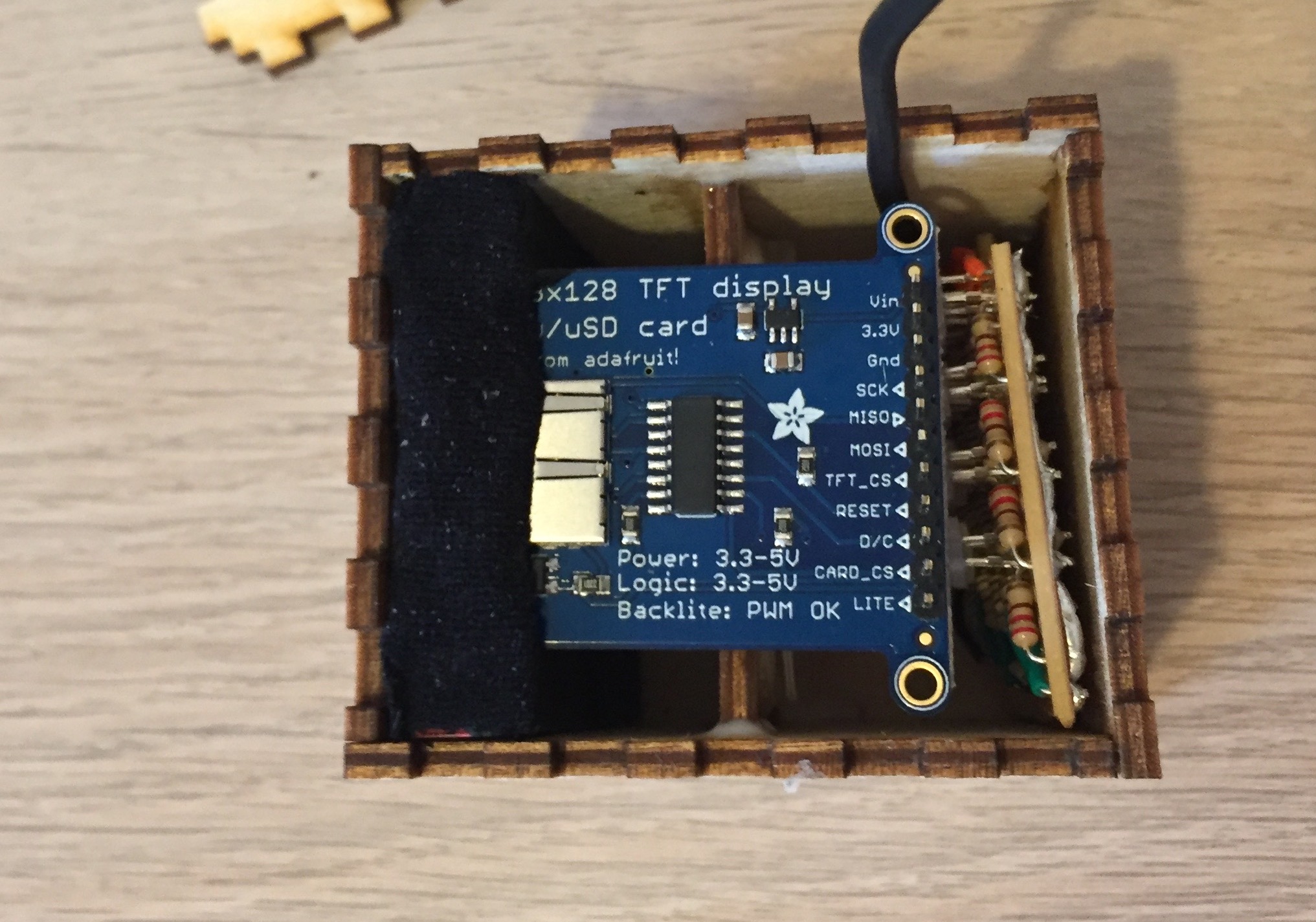
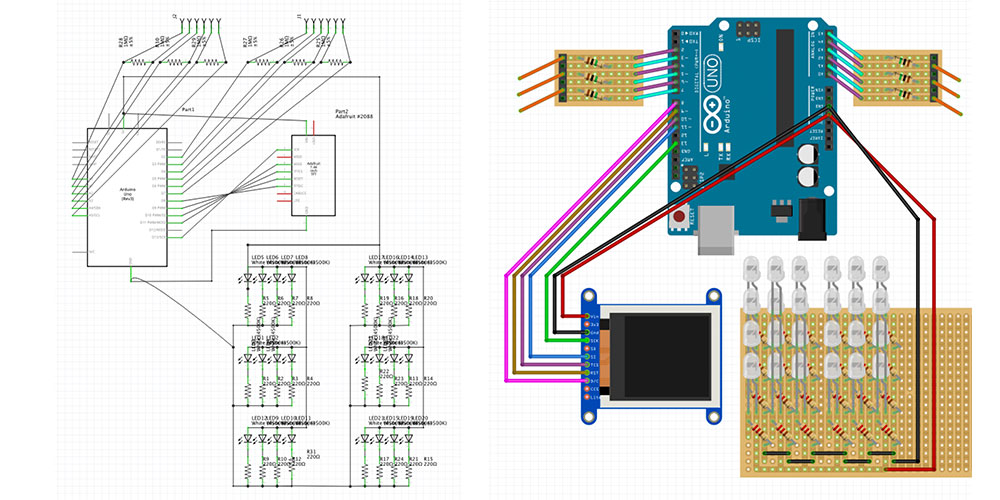
I wanted to make a very small projector that could potentially be embedded in any project. So I got a small breakout LCD screen that could be used with Arduino from Adafruit. I found out the basic technique of pulling apart an LCD screen from instructables like this one and some more in depth information about lenses and refracting light from this one on the Adafruit blog.
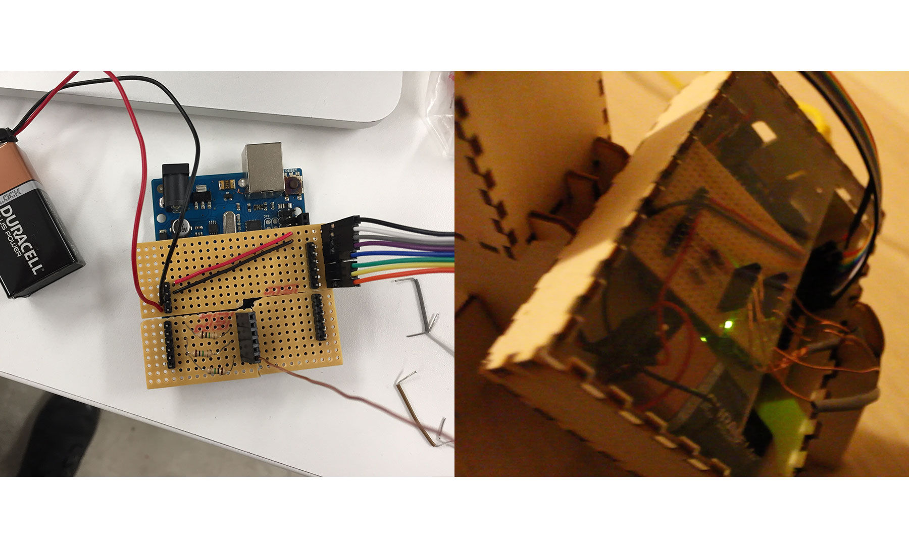
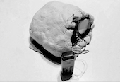
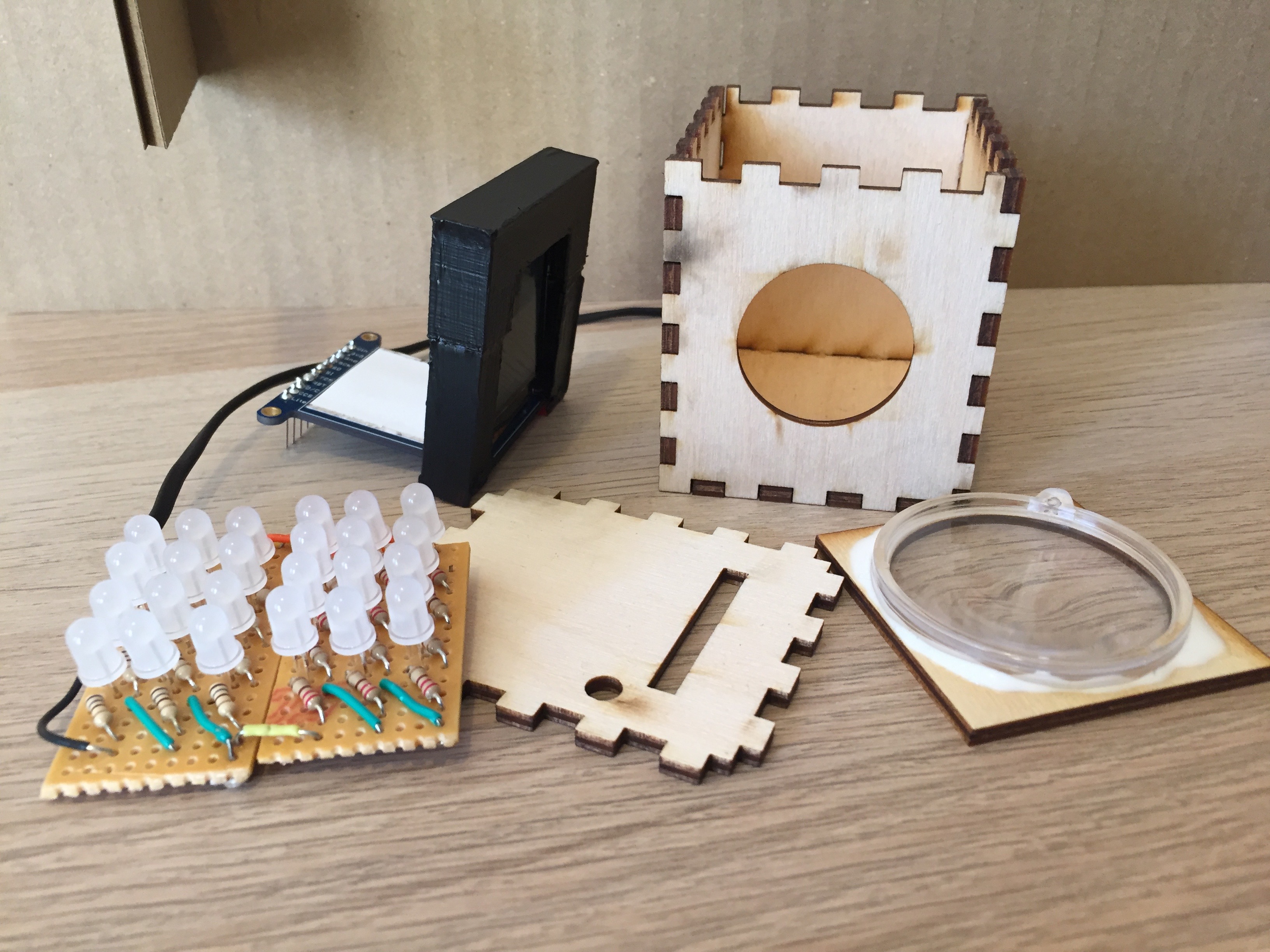
I pulled the back part of the LCD off, taking off as many layers as I could so that I could then shine a light through the screen. I tested with a phone and then soldered one panel of LEDs to shine through the LCD screen. I 3D printed a little support in order to hold the screen perpendicular to its base.
My first prototype of the projector was created using cardboard, tape and scissors. It was a functioning proof of concept. I was able to familiarize myself with the lens I was using and so understand what the throw of the projector was. The second prototype was laser-cut from cardboard.
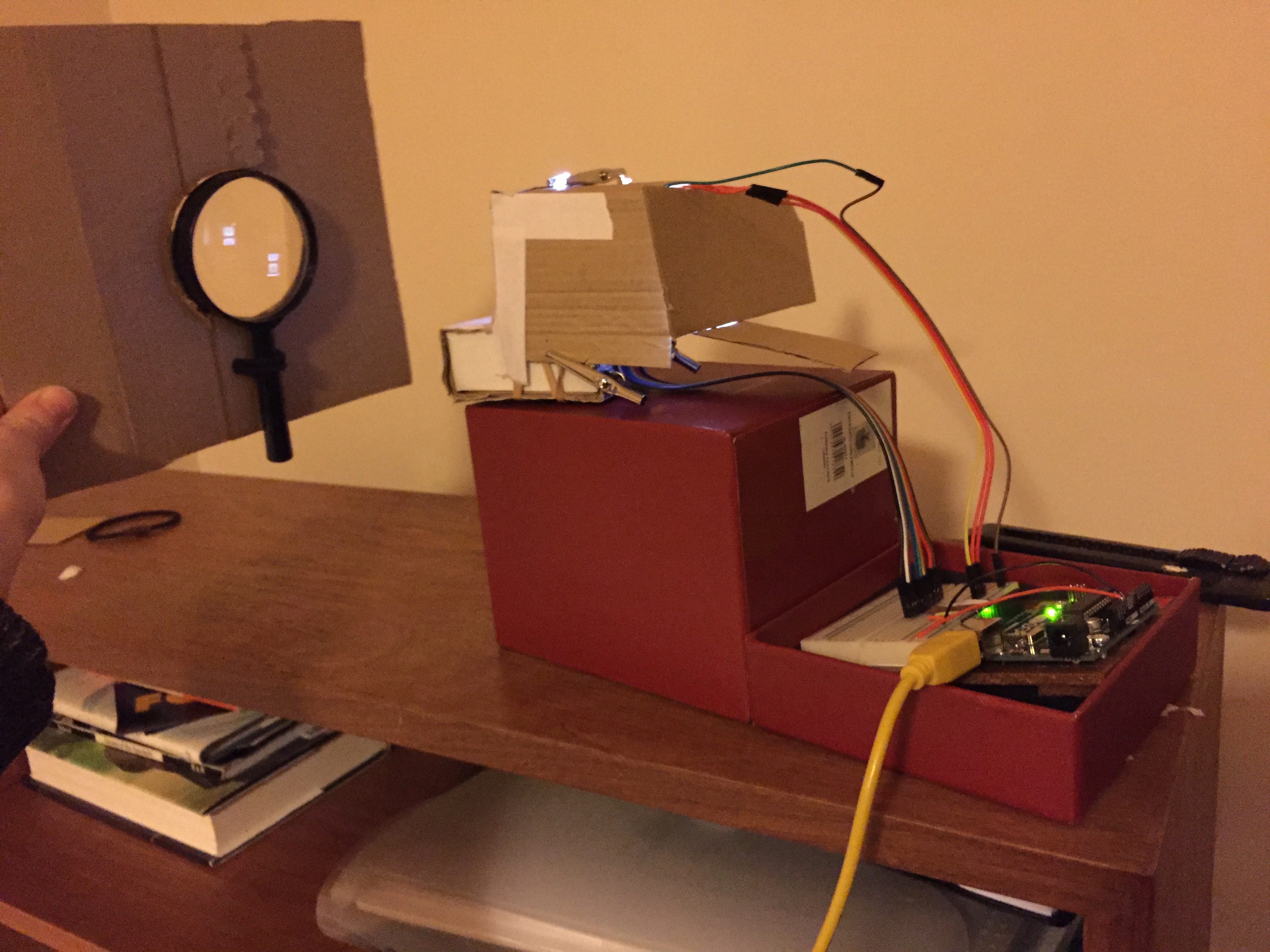
Based off of the first prototype I was able to generate measurements and start settling on a final design. It became apparent that including a focusing mechanism would be a good idea. And I decided to create a design that blocked light from the projection surface while also still meeting the aim of exposing the mechanics of the lens focusing and flipping the image from the LCD.
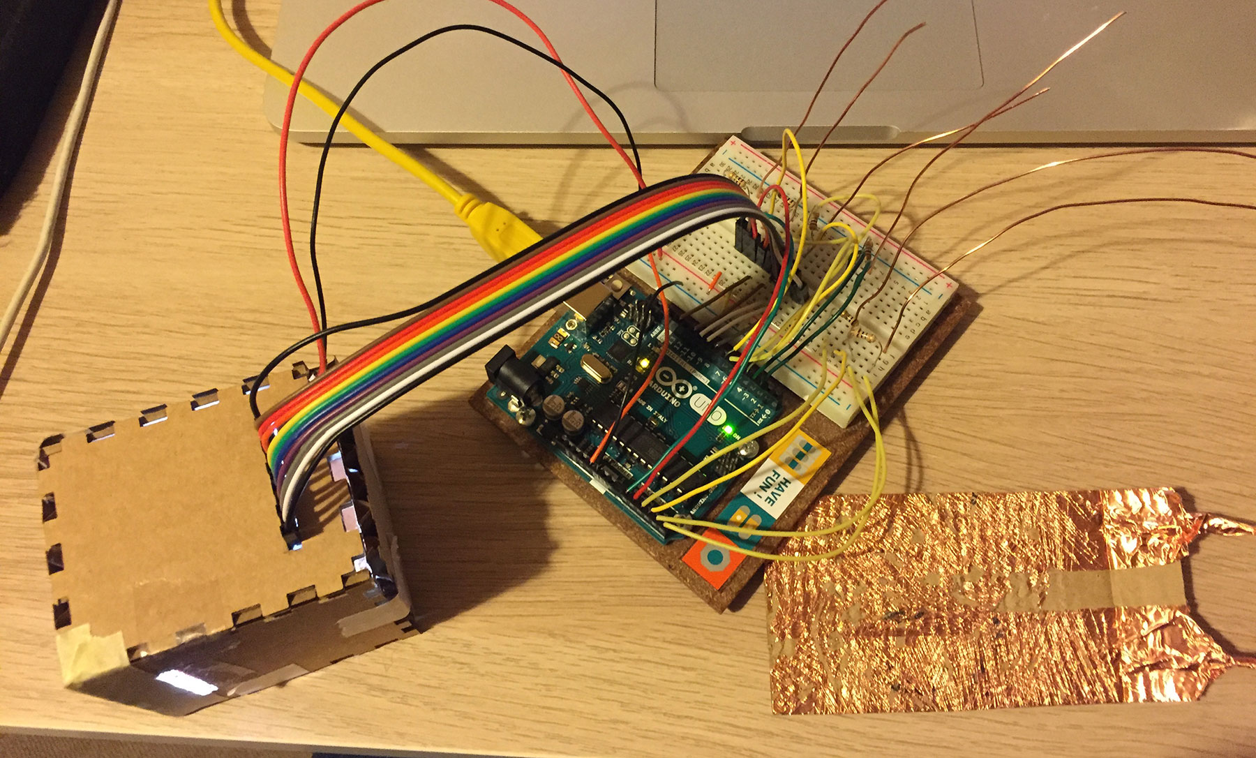
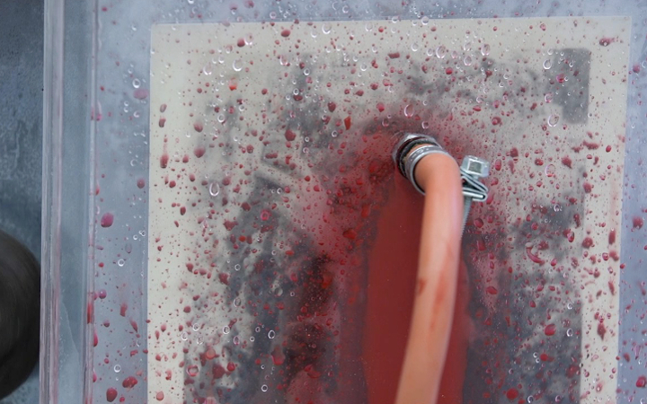
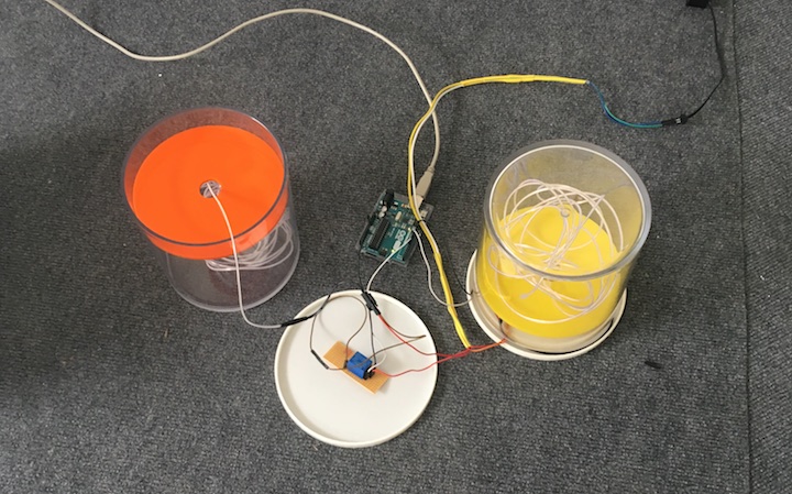
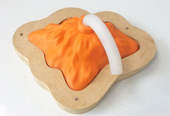
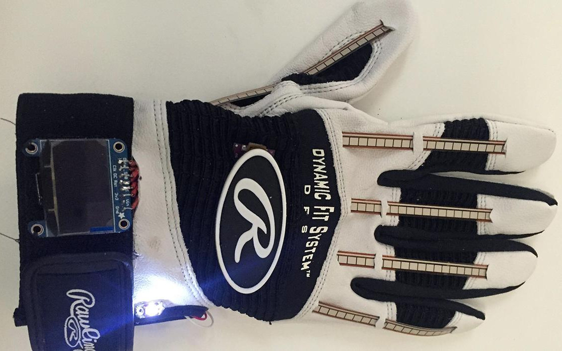
I wanted to create a range of capacitance so I decided to use and experiment with copper wire and tape. By cutting copper tape that I placed on a panel I was able to make a sensor that was more capacitive near the top where the copper tape touched the copper wire and less capacitive further down along the panel.
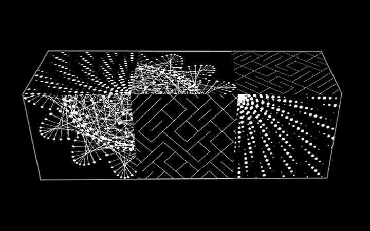
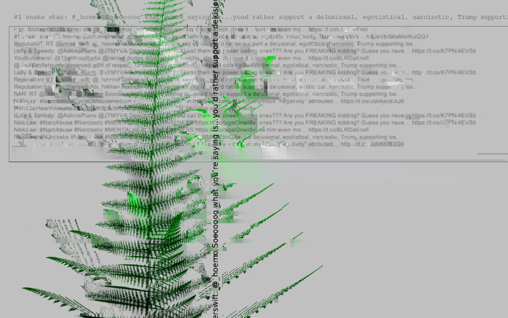
At first I experimented by creating an animation in Processing to represent the level of capacitance. And then I wrote some code for the Adafruit LCD screen using sample code from their graphics library. I used primitive shapes to draw shapes that represented the six sensors and the level of capacitance.
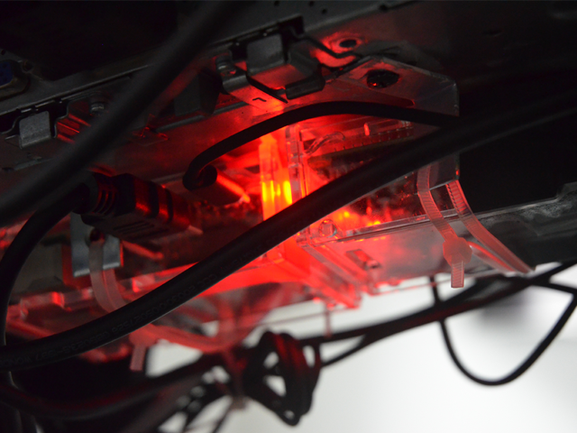
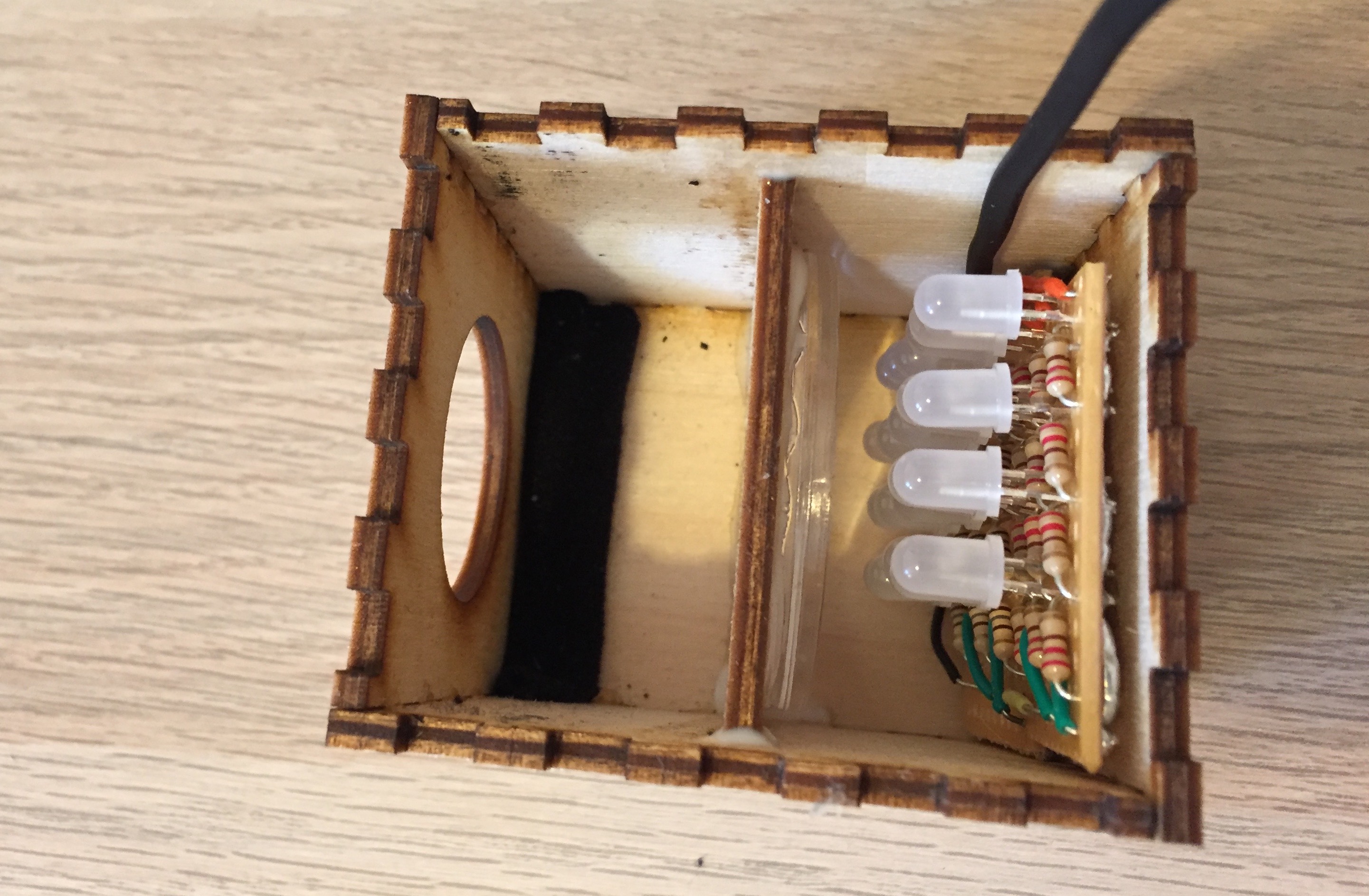
The final prototype was laser-cut from 3mm wood veneer. The back of the projector stand supports the Arduino box, and I made the decision to have a transparent acrylic lid so that the Arduino and soldered components could be seen by the viewer.