


Form and Structure
This project consists of a series of five individual studies which explore physical processes and the forms and structures that can arise from them.
produced by: Jakob Glock
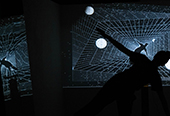
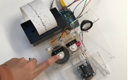
Astronomical Study
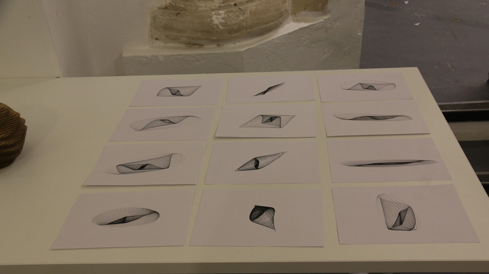
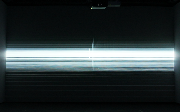
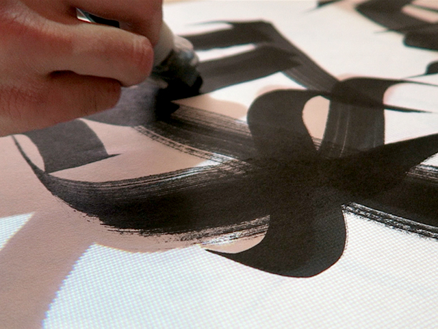
The concept behind this study was to explore how a physics based particle system could be used to create interesting and aesthetically pleasing forms which are drawn onto the screen over a short period of time. In my program I used Verlet Integration as the basis for my physics engine and proceeded to implement both attraction and repulsion forces, here I examined how the particles reacted to each force and came to the conclusion that depending on where the particles started, would determine the path they took within the screen. My next step was to explore different ways of drawing to the screen I achieved this by not refreshing the background of my program and setting low alpha levels to my particles colours so they left a trace of every position it had been in, this causes colours to be layered and ultimately build up over time. This layering of particles or points on the screen did not create the effect I was looking for, so I decided to experiment with calculating the distance between the particles and if the distance was within a certain range I would draw a line between the two points and use that to draw instead, this worked much better and produced a more natural free flowing forms.
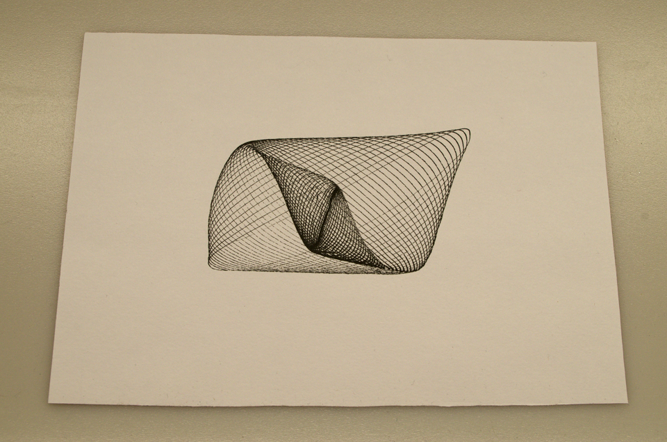
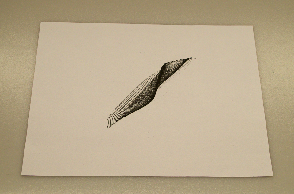
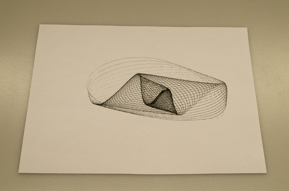
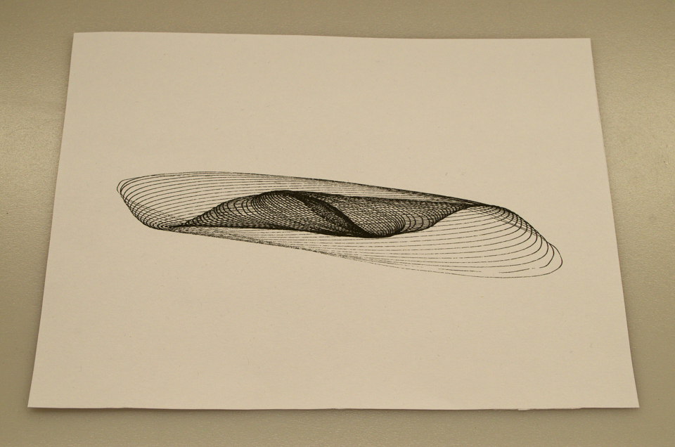
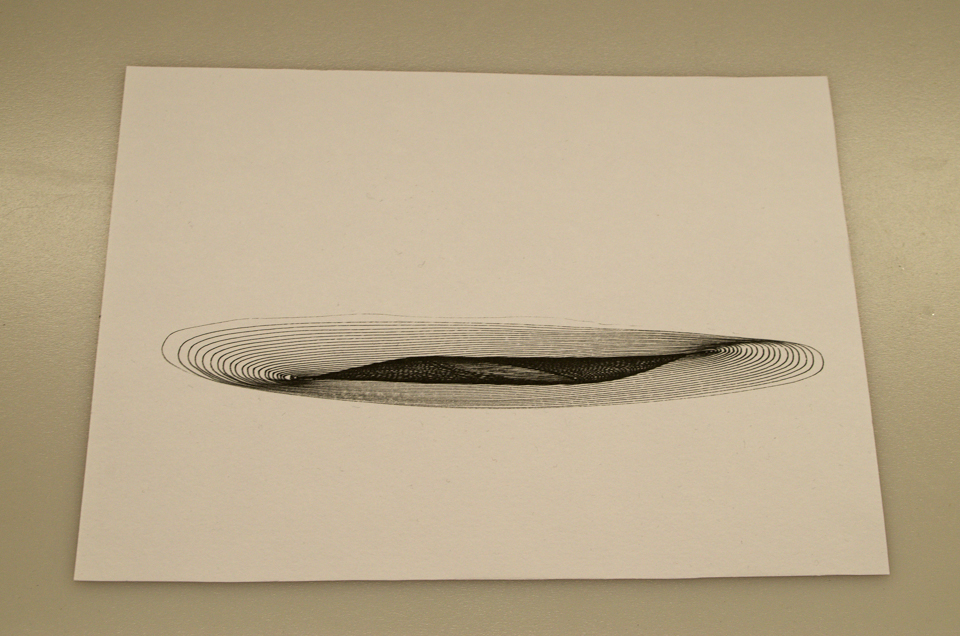
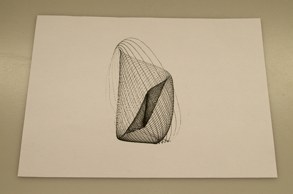
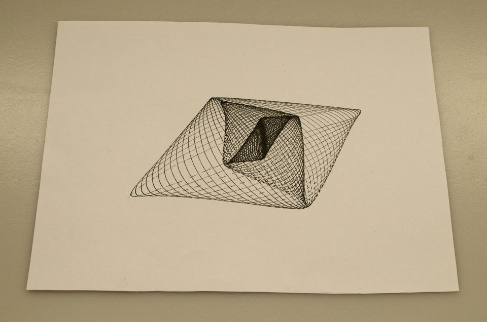
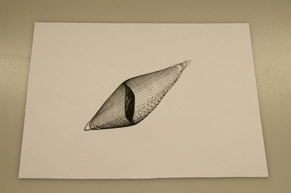
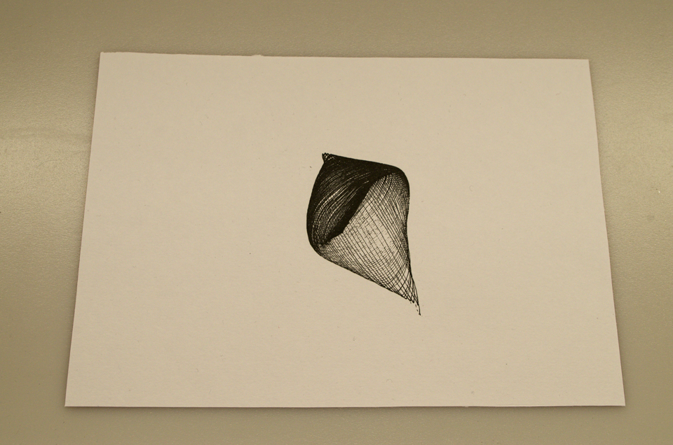
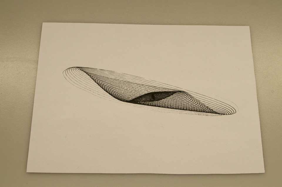
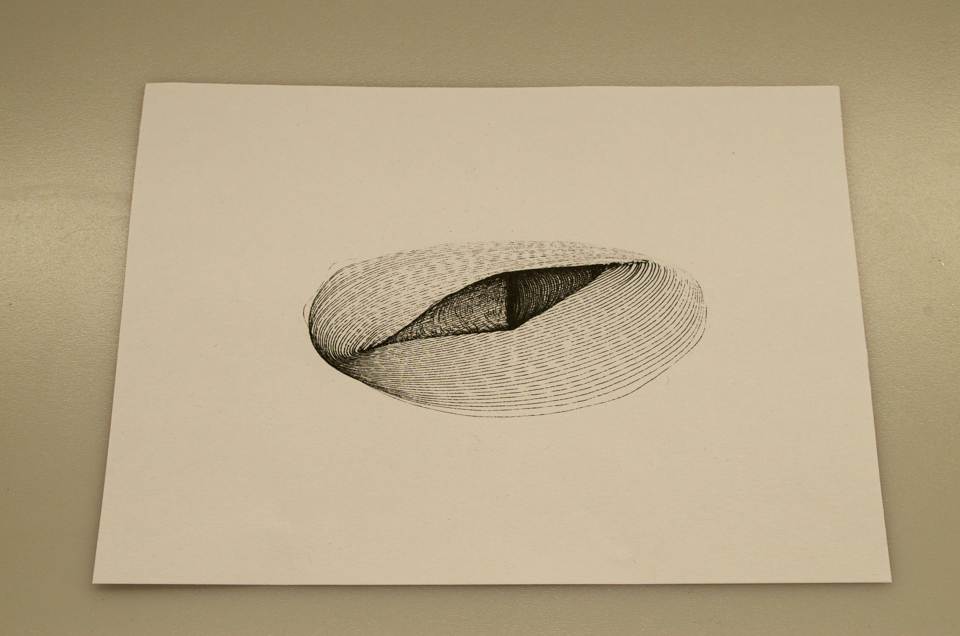
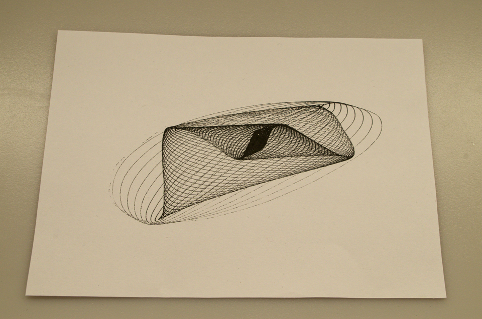
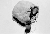
To create my physical artefact I decided to try and replicate the algorithm I used within my virtual artefact through the use of pendulums. Through much experimentation I came to the conclusion of connecting two pendulums together with a piece of string which had a pen suspended in the middle, by doing this I was able to place a piece of paper in front of the pen and plot the path it took as the two pendulums where put into motion. Once again I discovered that the output that was produced depended completely on the starting positions and swing speed of each pendulum and I was able to create a vast array of different forms.
References
- ofxGui used for the graphical user interface and is included with OpenFrameworks as standard
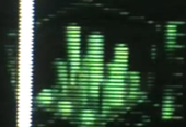
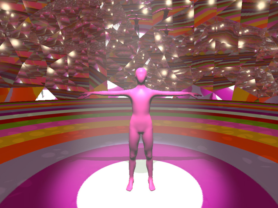
Planetary Study
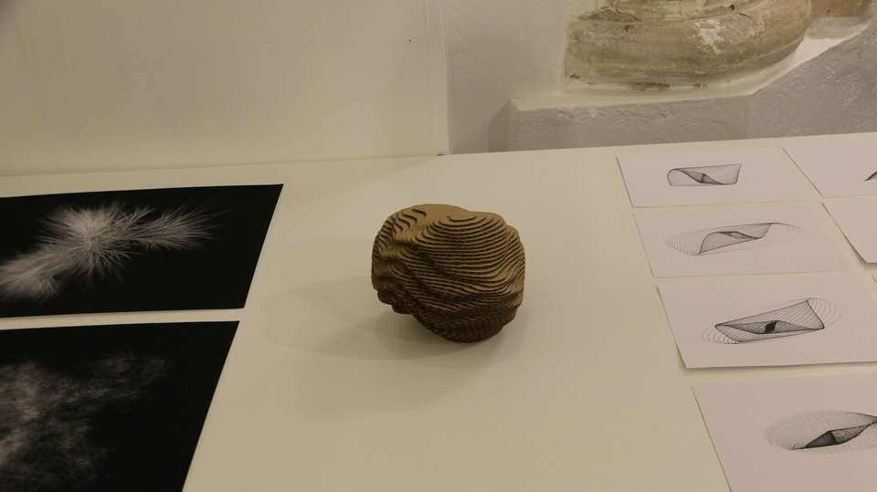
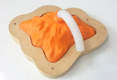
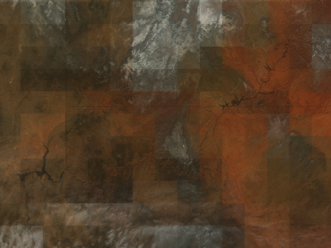
The concept behind this study was to explore the deformation of a spherical object through the use of sine waves to create abstract 3D forms. In my program I started by drawing a basic sphere to the screen and needed to devise a way in which I could control each vertex of the sphere independently. To achieve this I decided to explore the use of vertex shaders, this technique allows me to write a short program which describes how to manipulate a single vertex using the GLSL language, this is then compiled and ran on the GPU and each vertex in my program will be passed to this program and manipulated individually. The process taken within the vertex shader involves taking the current position of the vertex and offsetting it by a value calculated with sine and cosine functions, for example, the x position gets a value added by the sine of the current y position, multiplied by a frequency value. This allows me to create a deformed sphere which has an undulating surface which wraps around the surface perfectly, I decided to allow the user to be able to alter the settings which define the shape of the sphere so that they could explore a vast array of forms and have demonstrated this within my video, with a selection of my favourite discoveries.
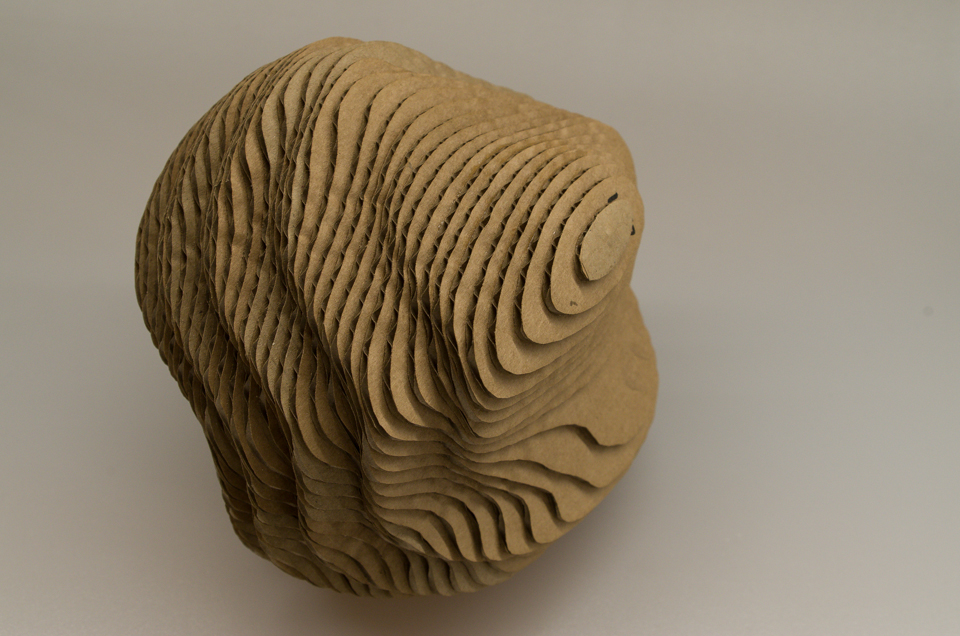
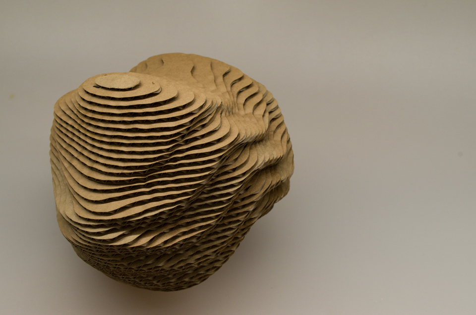
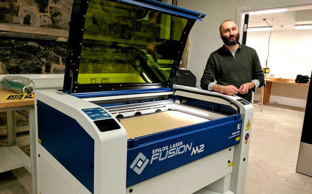
To create my physical object I decided to use a technique which involves layering cardboard to build up my object. The first step was to export the form from OpenFrameworks so that I could import it into the software package Blender, this was achieved by using the save function within the ofMesh object which saves the file in a .ply format to my hard drive. I then opened this within Blender and used a script called Laser Slicer, this script allowed me to define a slice size for example as I was using 2mm thick cardboard the slice size was set to 2mm. This generated a slice every 2mm along the slice axis of my object and the script would then save these slices into a SVG file, which I could then sent to a laser cutter to cut out. The next step once I had all my slices of cardboard was to stick them together to form my object, to make this process easier before I sliced my object I created three 3mm dowel holes which went through my object, these helped to align all my slices in the correct position when glueing it together.
References
- Gussian Blur Shader taken from OpenFrameworks shader examples.
- Blender software package used.
- Laser Slicer script used to slice my object into SVG files within Blender.
- ofxGui used for the graphical user interface and is included with OpenFrameworks as standard.
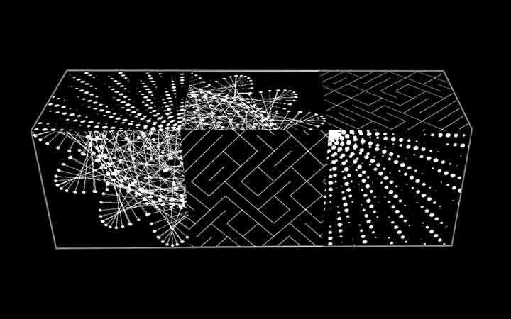
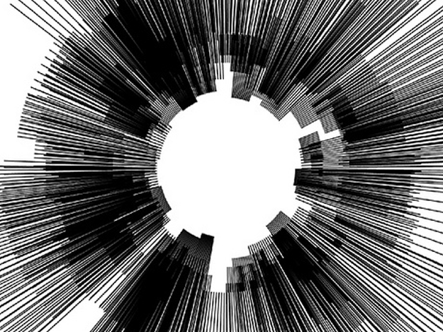
Environmental Study
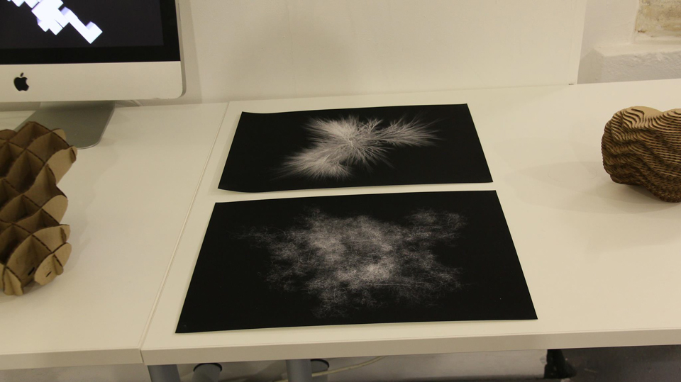
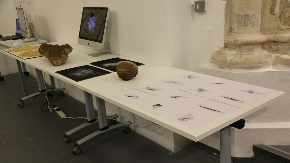
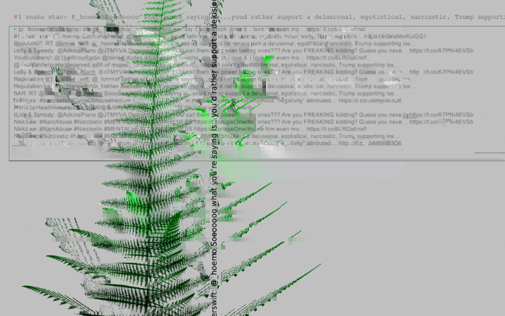
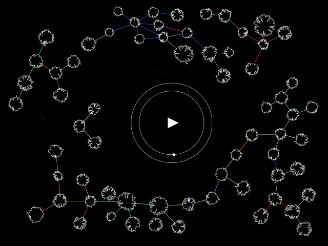
The concept behind this study was to explore how recursion could be used to generate a series of branching tree like structures in 3D space. My first step in creating my program was to build a class which defined a branch, at its most basic level this branch has a start and end position, a length and an angle at which the end position will be rotated by in 3D space. When a branch is created it sets off a chain reaction and creates a number of child branches, these new branches then create more branches and the process continues until a maximum number of branches has been reached. When a new branch is created it is passed various values from its parent branch such as the end position, which will become the child starting position, this ensures that all the branches are connected together. As well as this, the parents angle is passed to the child so that the new branch can be offset from this angle creating a more organised interrelated structure within the tree. In refining my program I discovered a wide variety of forms and decided to document each stage of the process until I came to the form I was looking for, in my video I have included screenshots of a selection of these different forms. Most of these forms involved a large amount of points and lines and due to the high resolution I was creating them in where not realtime programs, this meant that I had to wait sometimes around 20 minutes until a new form was rendered to the screen and I could export it as an image. The program itself is able to produce a new form based on random offsets at the click of a button in realtime, whilst following a similar aesthetic.
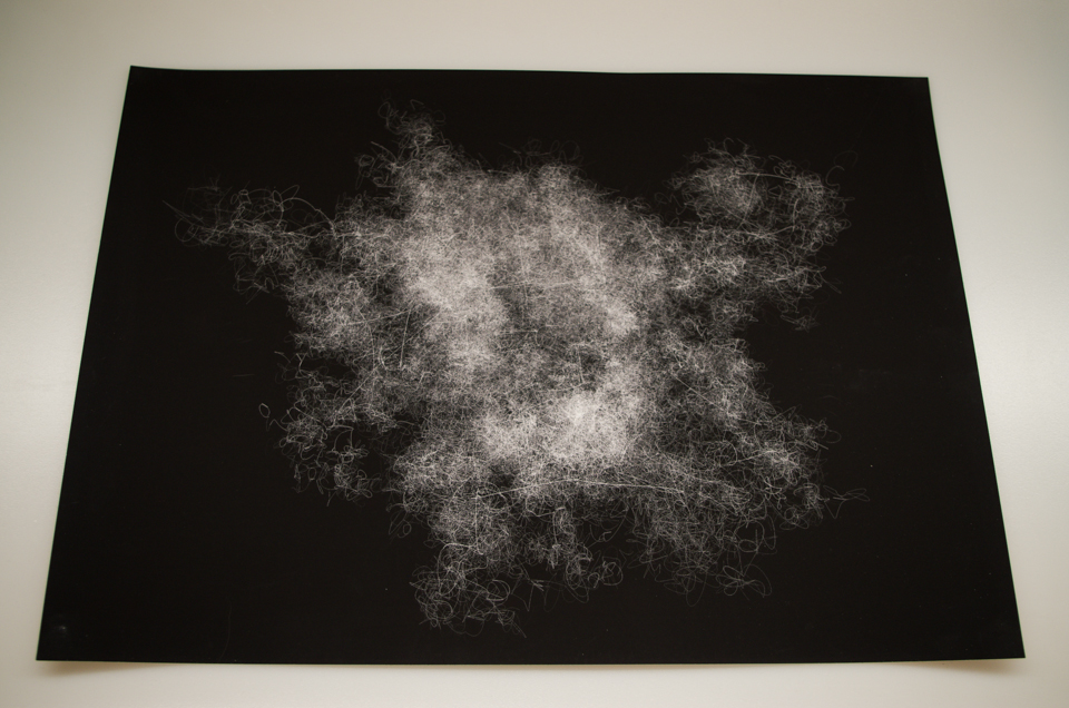
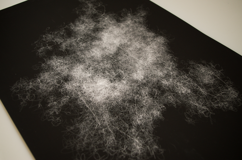
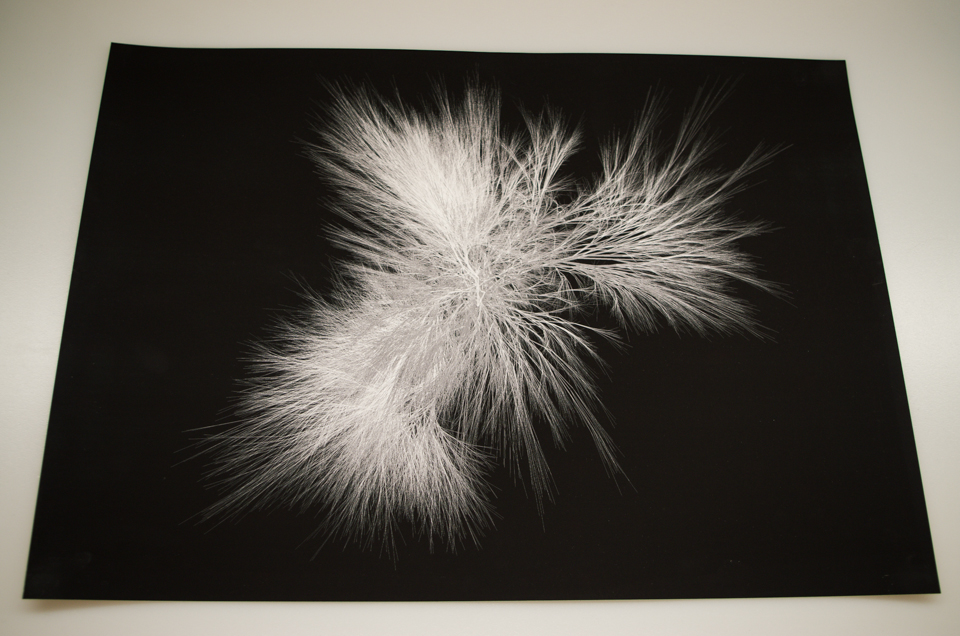
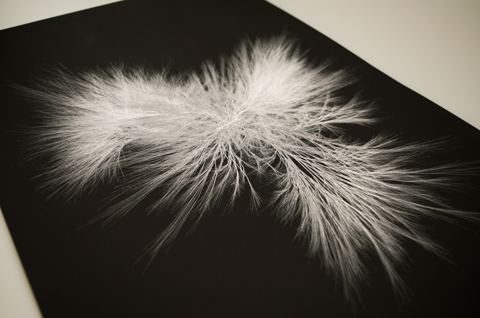
To create my physical artefact I decided to choose two contrasting screenshots and get them professionally printed onto A3 paper. The process I took was relatively simple and involved exporting my images at a high resolution of 4962px × 3508px which allowed me to get my prints done at 300DPI. The printing technique used was 'Giclée' inkjet printing, the paper I chose to use was 'Innova White Matte 285gsm' which was advertised as producing brilliant whites. These prints came out extremely well, with brilliant contrast between the white and black and with extreme detail.
References
- Code inspired by chapter 8, 'Fractals' in 'Generative Art' by Matt Pearson.
- Giclee printing
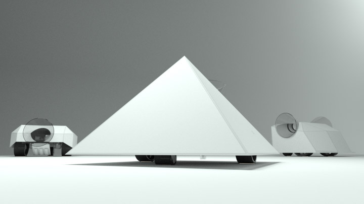
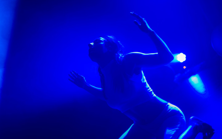
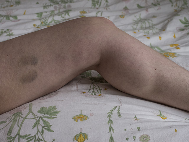
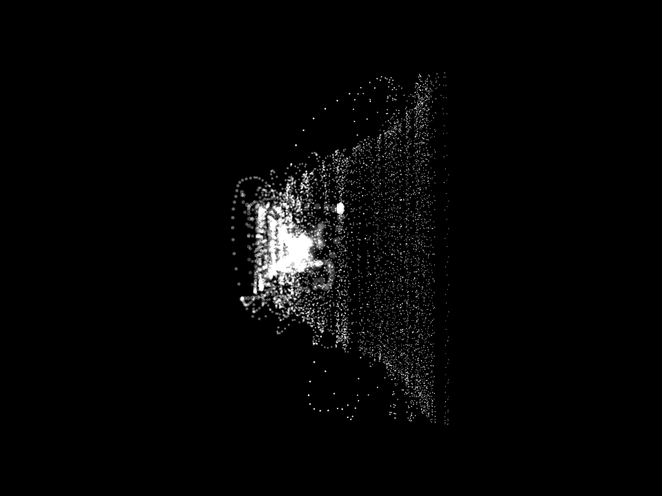
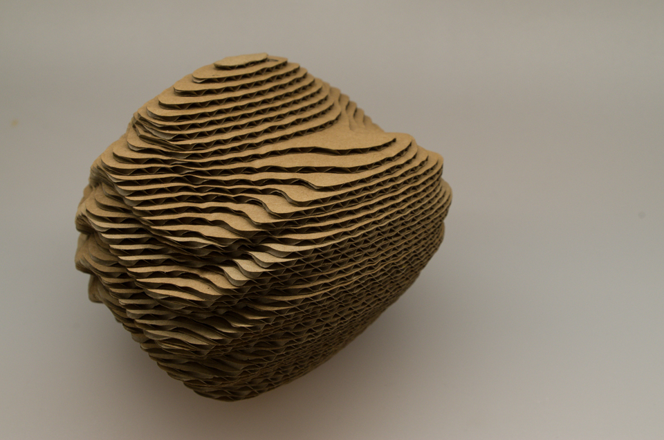
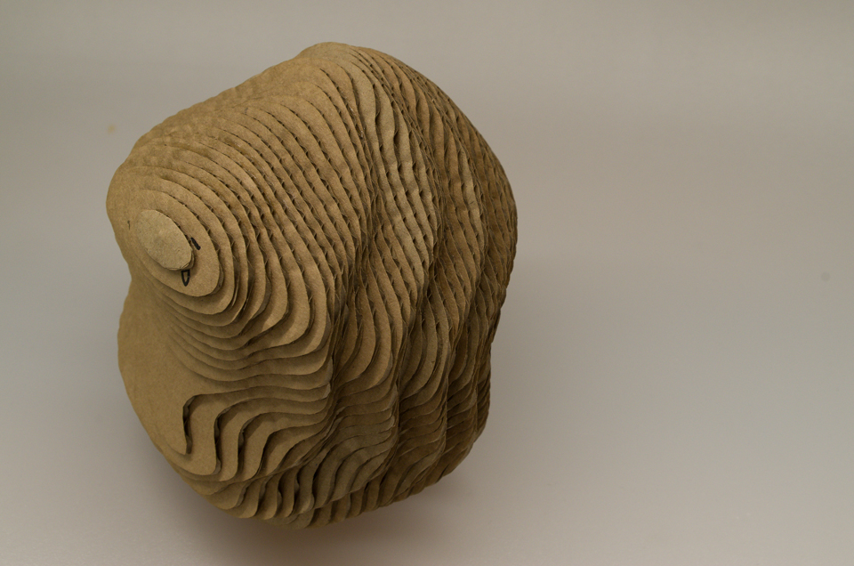
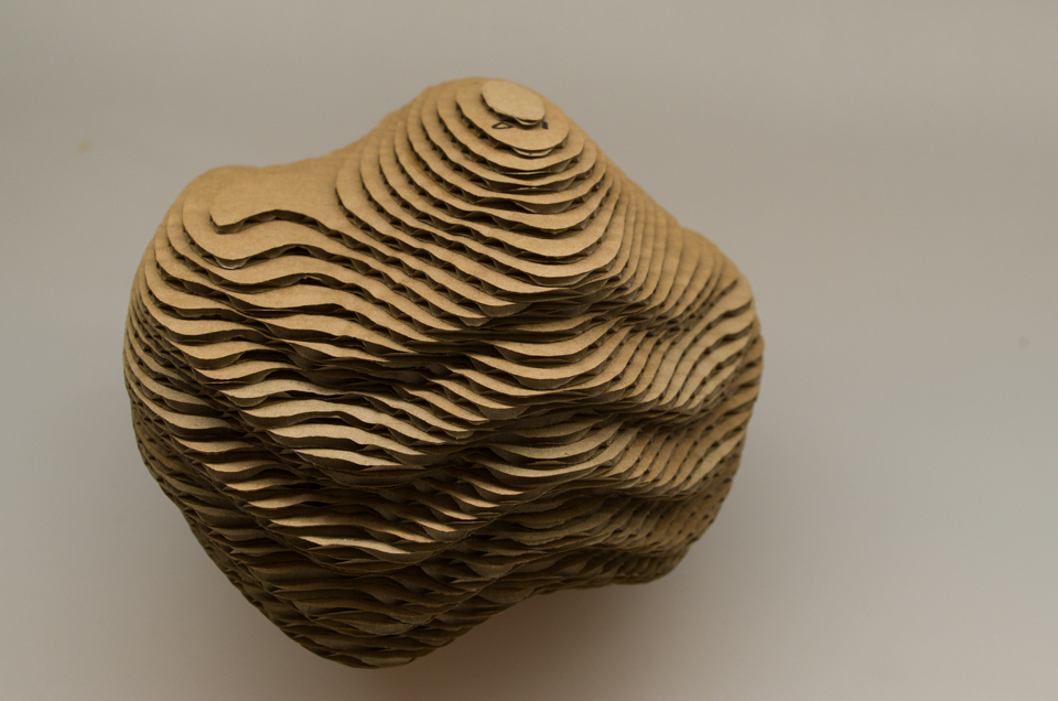
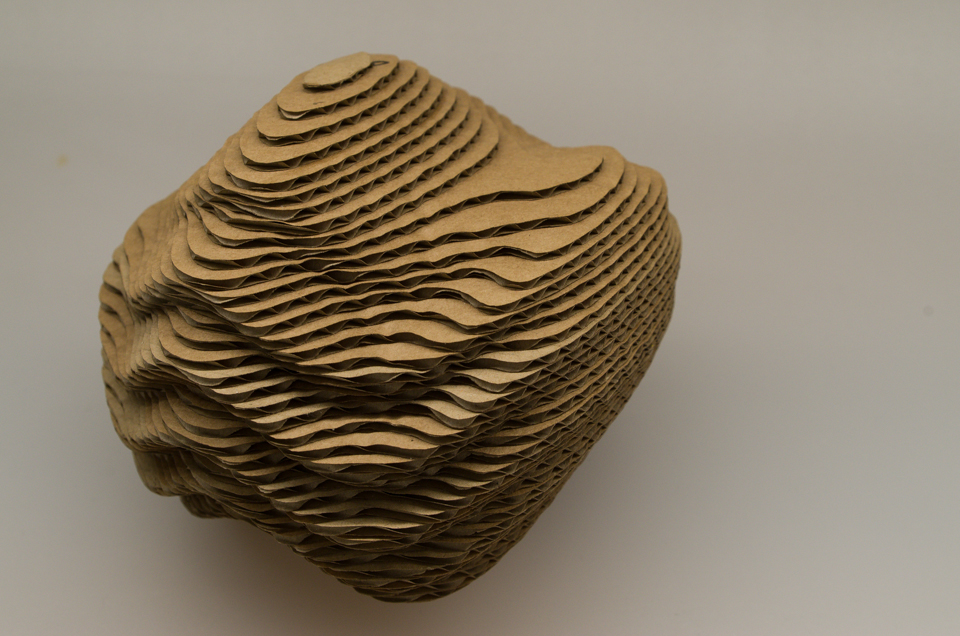
Human Study
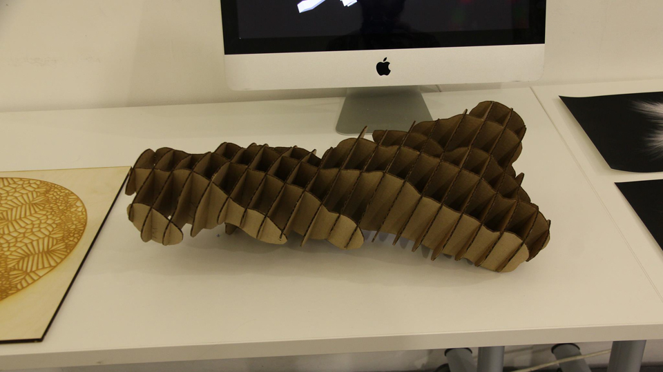
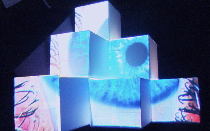
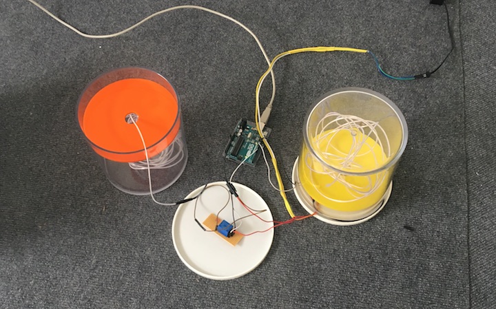
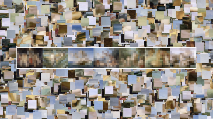
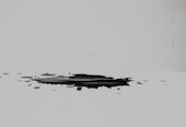
The concept behind this study was to devise a way of creating a 3D structure that could be seen from the human view point. In my program I decided to explore the use of a DLA (diffusion limited aggregation) algorithm as the method to build my structure. This algorithm creates a number of particles which move around randomly within a defined space. At the start of the algorithm there is a seed form of a single particle, as the particles move around randomly within the space they might collide with this seed form, if this happens they will stick to it and be added to the seed form. As the process develops the form is slowly built up over a period of time finally creating the finished form. Usually these algorithms use circles for the particles, but I decided to use cubes as I wanted to see if the algorithm could produce more structured human built forms. By using cubes it meant that I had to move my cubes around in a more constrained way, for example a cube can only move by one unit in any direction, this meant that my cubes never actually collided but could potentially be beside another cube within my main form, if this condition was met then the cubes would stick together and be perfectly aligned.
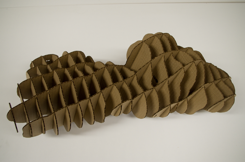
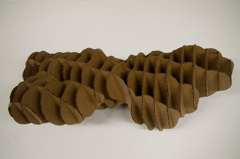
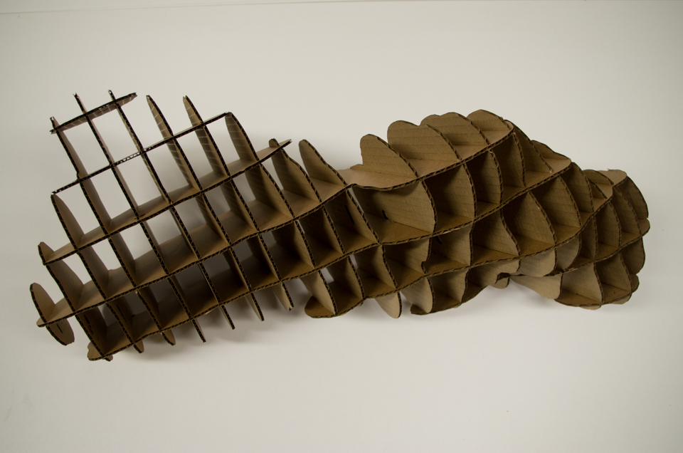
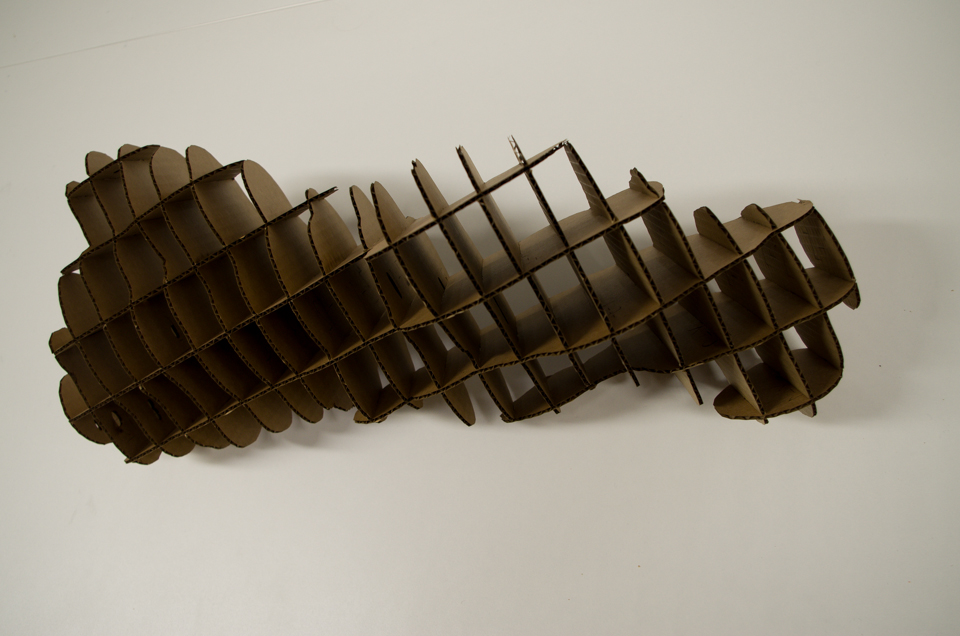
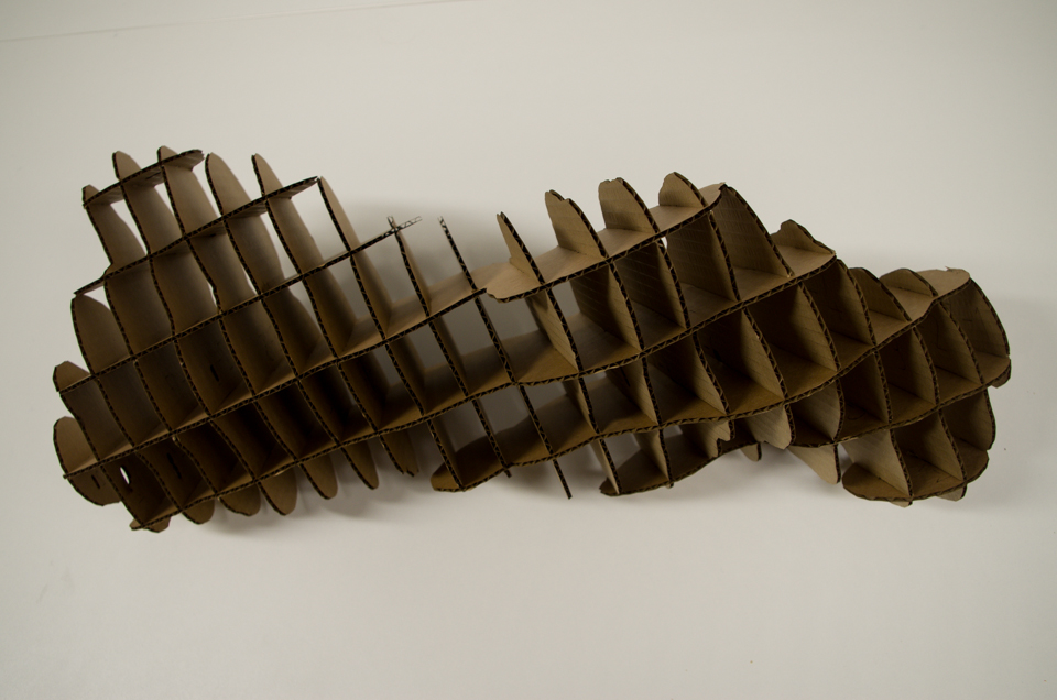
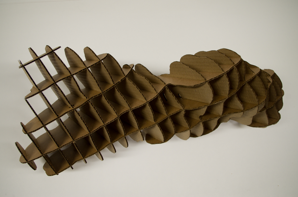
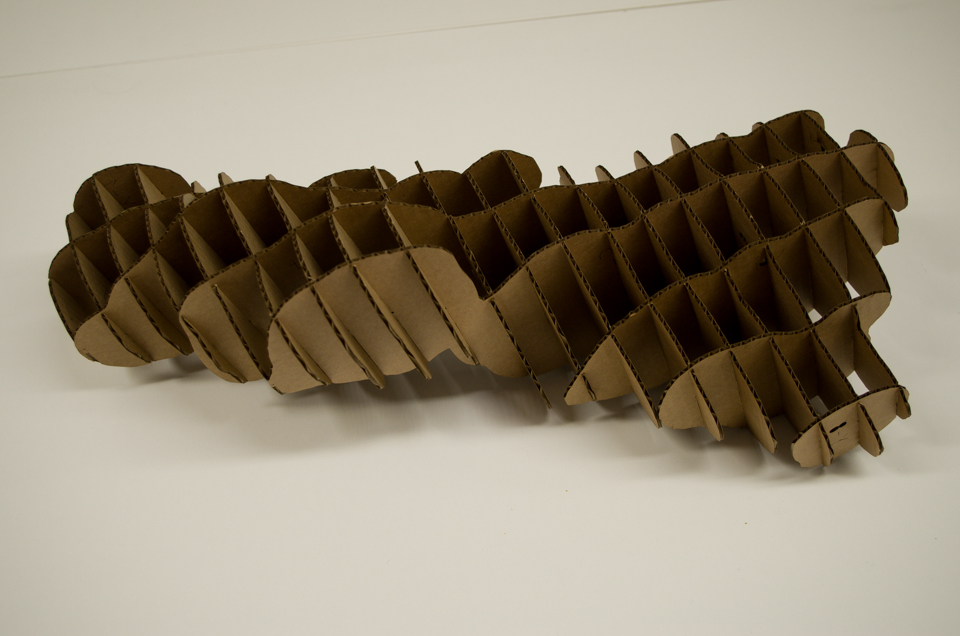
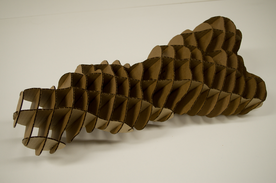
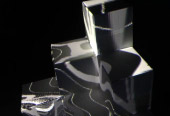
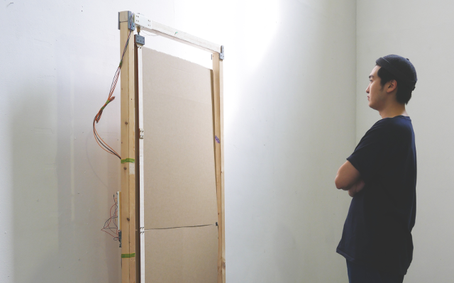
To create my physical artefact I decided to explore a similar route to my planetary study and choose to use cardboard as my material. Only this time I wanted to create an interlocking structure instead of a layered one. To achieve this I first had to export my object from OpenFrameworks so that I could load it into an external software package and generate my interlocking slices. The software I chose to use was Fusion360 and the add-on Slicer. This software allows for a 3D object to be loaded and then sliced in various ways, these slices are then exported into a PDF files and can be used as data for a laser cutter. Before I could generate my slices I had to use a feature within Slicer called shrink-wrap, this feature places a surface around your object and produces a more rounded look, this was done as my object was very thin in places and could not be sliced perfectly, using this feature essentially made my object larger whilst still keeping the basic shape visible.
References
- Code inspired by Paul Bourkes explanation of the DLA algorithm.
- Slicer addon for Fusion360 used to generate my interlocking slices in PDF format.
- Inkscape used to convert PDF to SVG and do minor editting ready to be cut on the laser cutter.
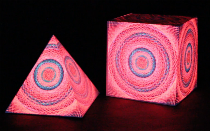
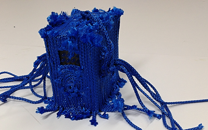
Microscopic Study
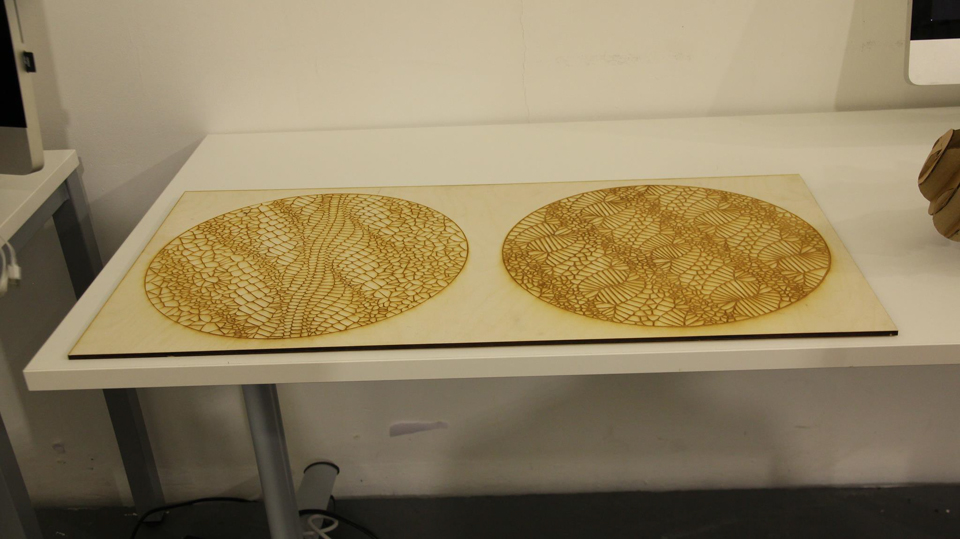
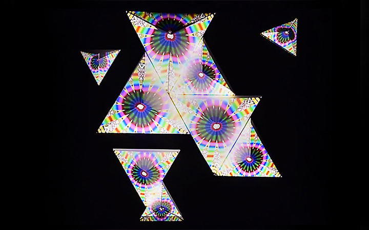
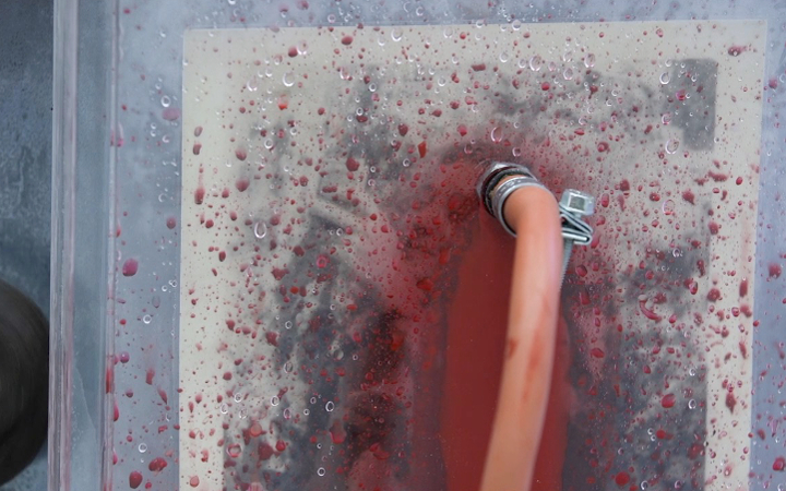
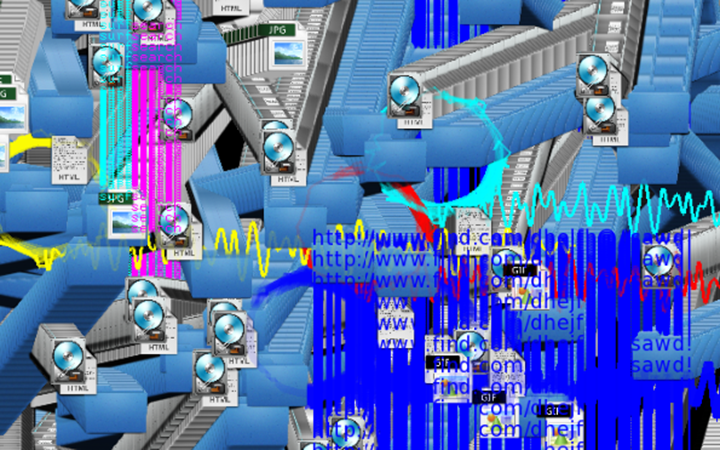
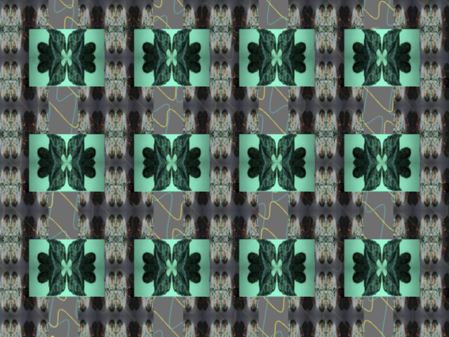
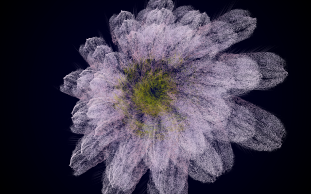
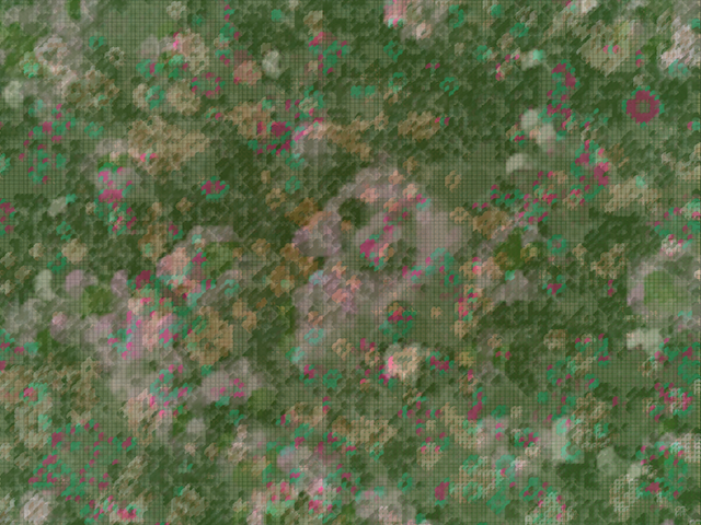
The concept behind this study was to explore how cell wall like structures could be created using a grid of points and a Voronoi pattern. In my program the first step was to create a grid of points and then deform the structure in some way, the way I devised was to create a grid of springs with a particle on the end of each one, if looking at these springs in real life you would be looking at the top of the spring down, so you will only see the end which is able to move in two dimensions. From here I decided to apply a unique force to the particle on the end of each spring, this force was calculated using sine and cosine functions and the mouse position and would be applied to the particle to cause it to move, because this particle is connected to a spring a counter force would be calculated for the spring and limit or constrain the movement of the particles. My next step was implement the Voronoi Pattern, for this I used the OpenFrameworks add-on 'ofxVoro', this gave me a few options that other add-ons did not provide. One of these was the ability to apply a container around my Voronoi Pattern, this can be seen with the circles that the pattern is within. This decision was taken because I wanted to give the effect of looking through a microscope or these structures being in a petri dish.
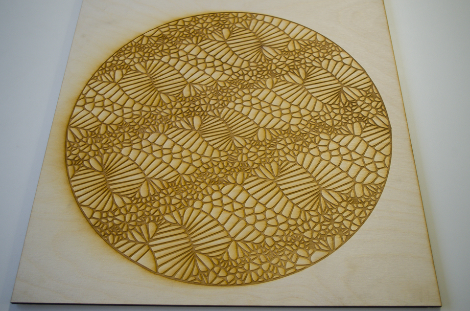
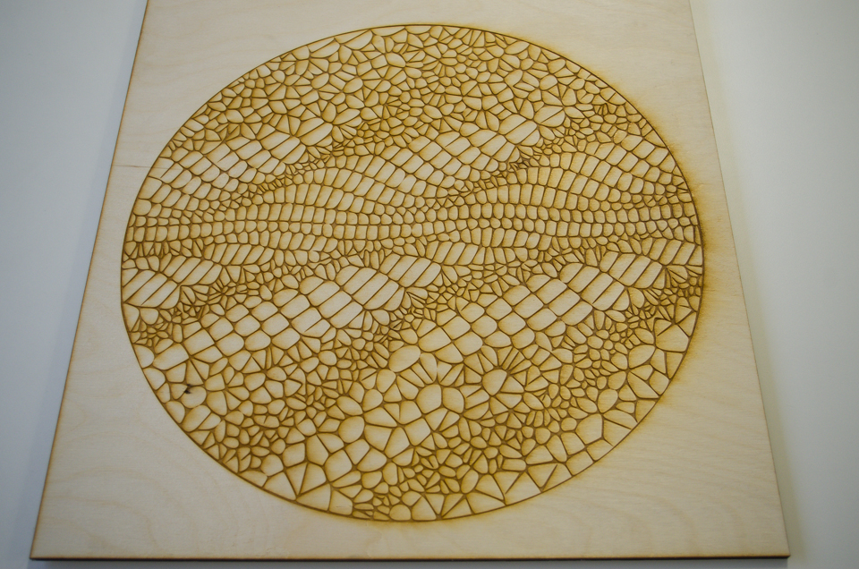
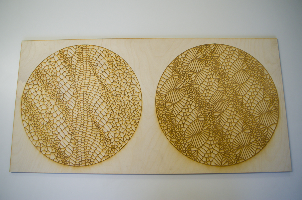
To create my physical artefact I decided to use the laser cutter to engrave into a piece of 6mm thick plywood. My first step in achieving this was to export screenshots of my virtual object, I could then use the software package Inkscape to trace my image into an SVG file. Once my image was traced I did a test engrave on a smaller piece of plywood to test out different settings for the engraving and decide on my layout. I really liked my initial test and proceeded to enlarge my object onto A1 size, in doing so I decided to keep one of the dimensions equal to the A1 format of 841mm, and decreased the other dimension to 420mm as this gave me an equal border around my design and I felt worked better. One of the downsides to engraving on wood is the material can be stained by the smoke that is produced, there are various methods to either remove or prevent this as I have recently found out after creating my object. A material that I think would have worked better is black anodized aluminium, when this is engraved you are left with a silvery white mark which produces a great contrast and I will be experimenting with in the future.
References
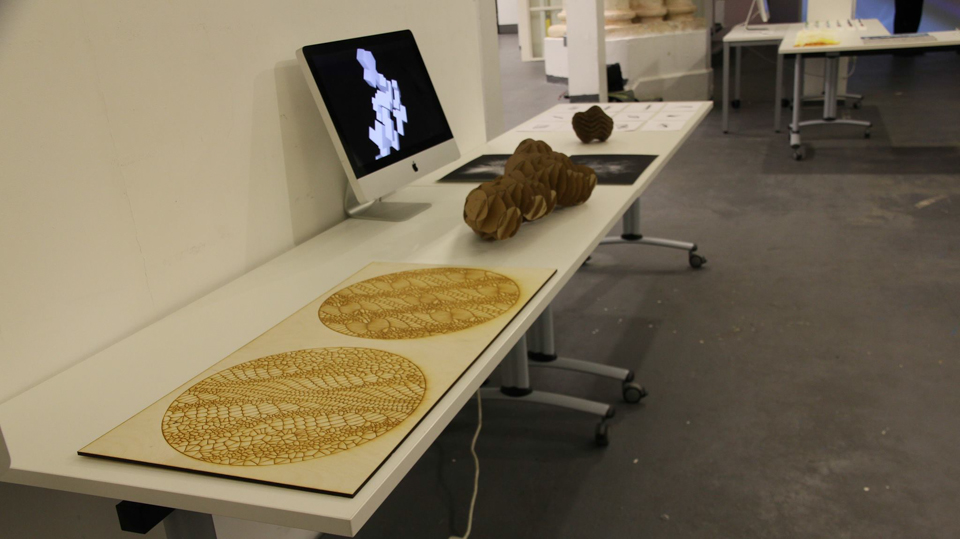
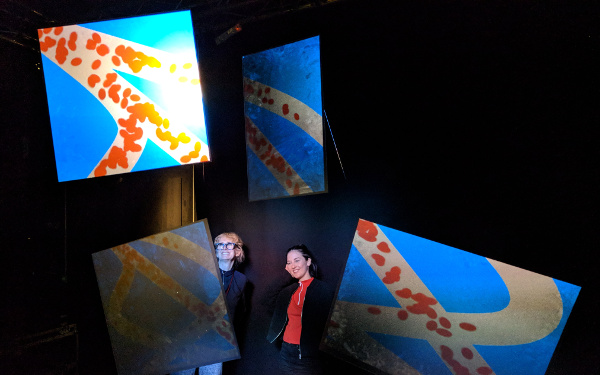
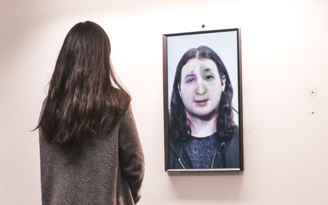
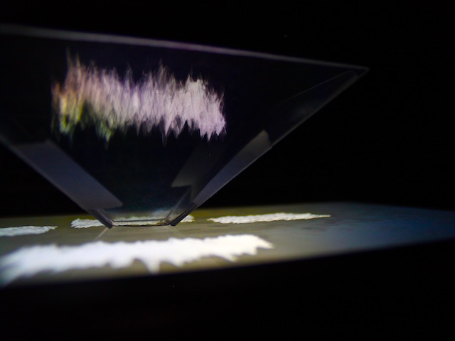
Exhibition
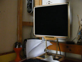
Presenting my objects in the exhibition meant that I had to think about how to structure my work for people to view whilst still working in a wider context. All of my physical objects where laid out onto a flat white surface in the order that they where created and increasing in size. To display my virtual objects I decided to create a video loop of all my studies to played on a screen positioned on the table. I felt this worked well, but I could have gone one step further and had a brief explanation of a few sentences for each study so people could read and gauge a deeper understanding of the work they where looking at.