


Light Up Shoes
By Julia Makivic
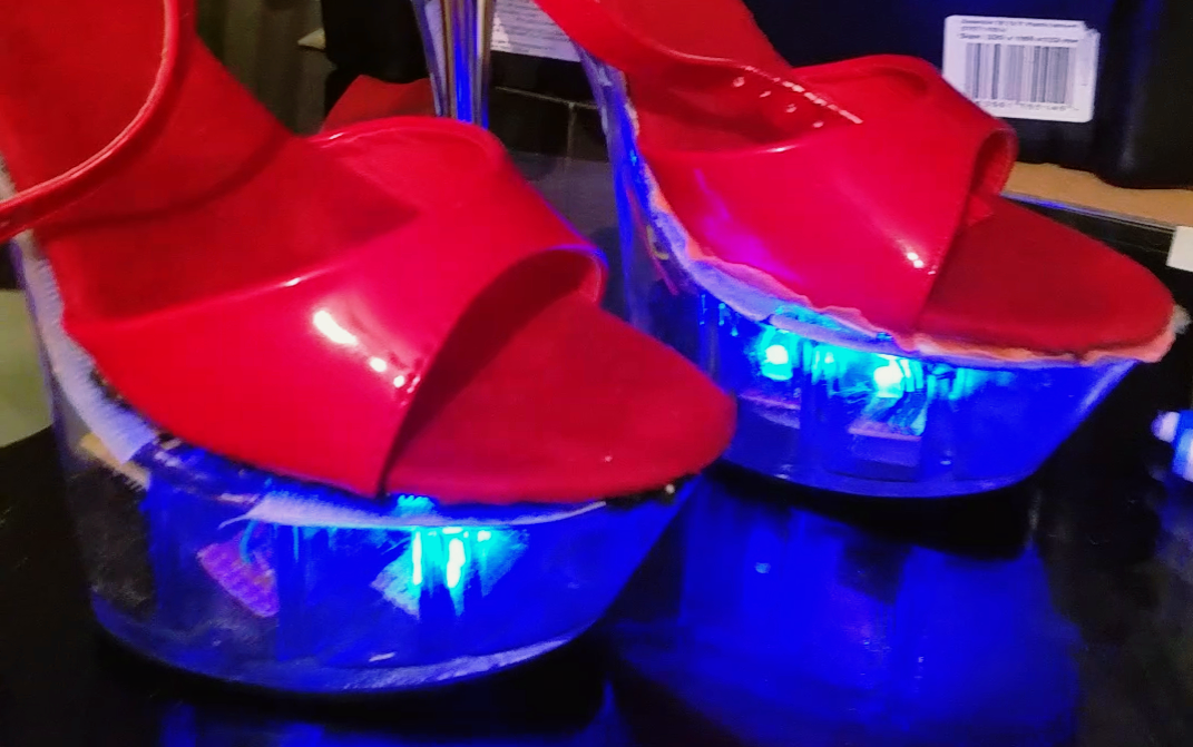
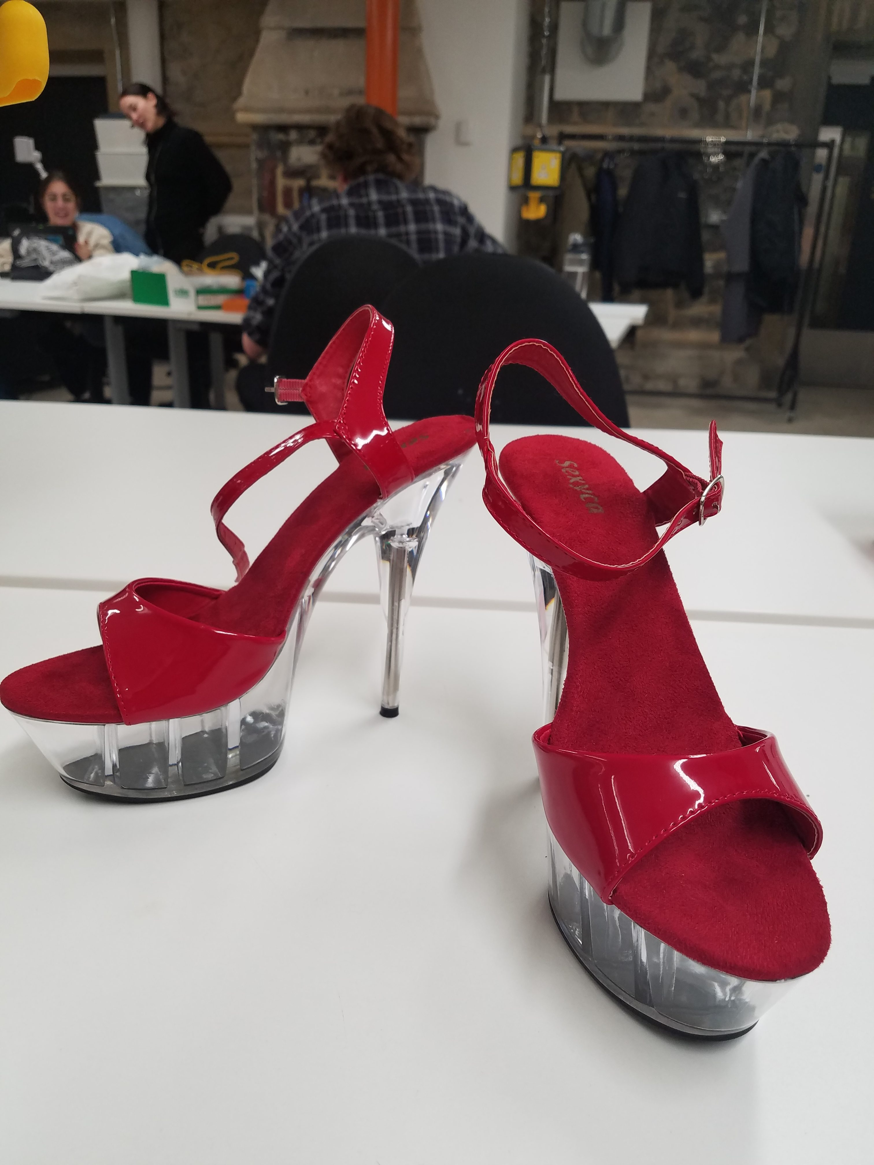
For my Physical Computing final project, I wanted to create a pair of light up high-heeled shoes. I’ve been doing pole fitness for a little bit over a year and some styles of pole dance incorporate a pair of shoes with clear heals like the ones pictured below. I thought it would be interesting to use that space inside of the heel to store LEDs and display different light patterns. The lights could change according to some movement and therefore the change in light pattern could complement the dancer’s choreography.
When starting this project, I realized that my biggest challenge would be figuring out how to fit all of the components I need inside of the shoe. The inside is hollow and broken up into separate compartments. I decided to use these divisions to store different parts of the circuit.
In order to be able to fit the circuit into the shoe, I realized that I would have to use a smaller microcontroller than the ArduinoUno. I decided to use the Arduino Pro Mini because it was much smaller than the Arduino Uno and could easily fit into one of the sections in the heel. However, it still used an ATMega320 microcontroller and transferring code from the Arduino Uno into the Pro Mini was very simple. It also had a similar number of analog and digital pins and multiple pins for power and ground.
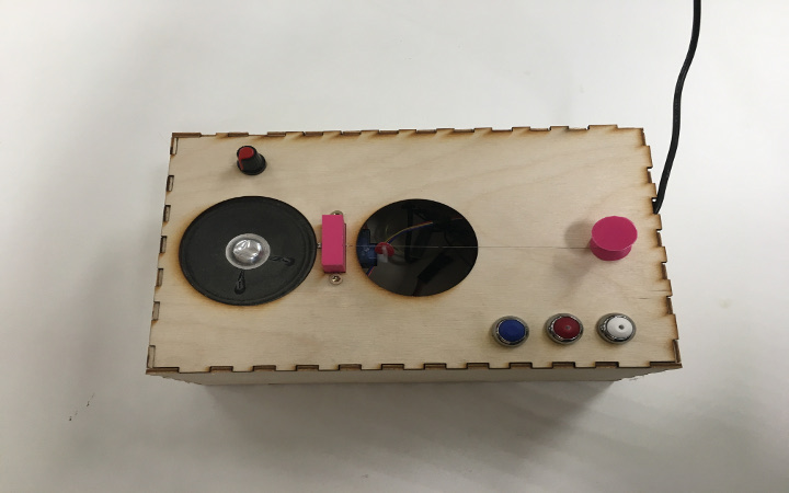
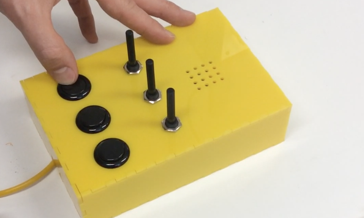
In order to test it, I tried to see if I could transfer the code for Project 2: Starship Interface onto the Arduino Pro Mini. Below is a video of the circuit for Starship Interface being controlled by the Arduino Pro Mini.
Arduino Pro Mini Running Starship Interface from Julia Makivic on Vimeo.
I decided that the main interaction with the shoe would be triggered by a tilt switch. Pole dancers spend much of their time upside down on the pole, therefore I thought that it would be interesting to play with the vertical nature of this type of dance. I decided to make the orientation of the shoe determine the color of the lights. If they were upright, they would display one light pattern and if they were upside down they would display another light pattern.
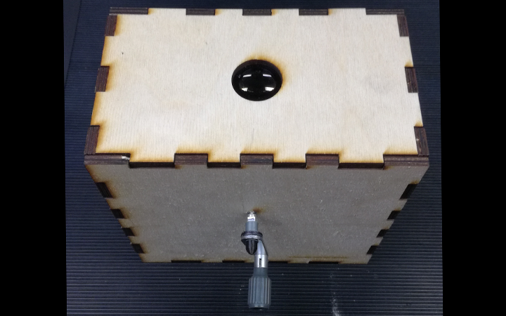
The entire circuit would be powered by a 9 volt battery.
The Arduino code sets the color of the lights one set of colors when the tilt switch is upright. It loops through a series of colors while it is upright, creating a flashing effect. When it is turned upside down, the light changes to another set of looping colors.
Initially, I wanted to use RGB LED lights that I had ordered as the source of light within the shoe. The lights would be soldered onto a breadboard in a single row. The pins for each color would be connected to a digital pin on the Arduino. The cathode pin would be connected to ground. Here is a video showing this circuit on a breadboard.
20171207_192905 from Julia Makivic on Vimeo.
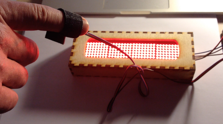
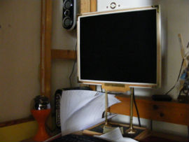
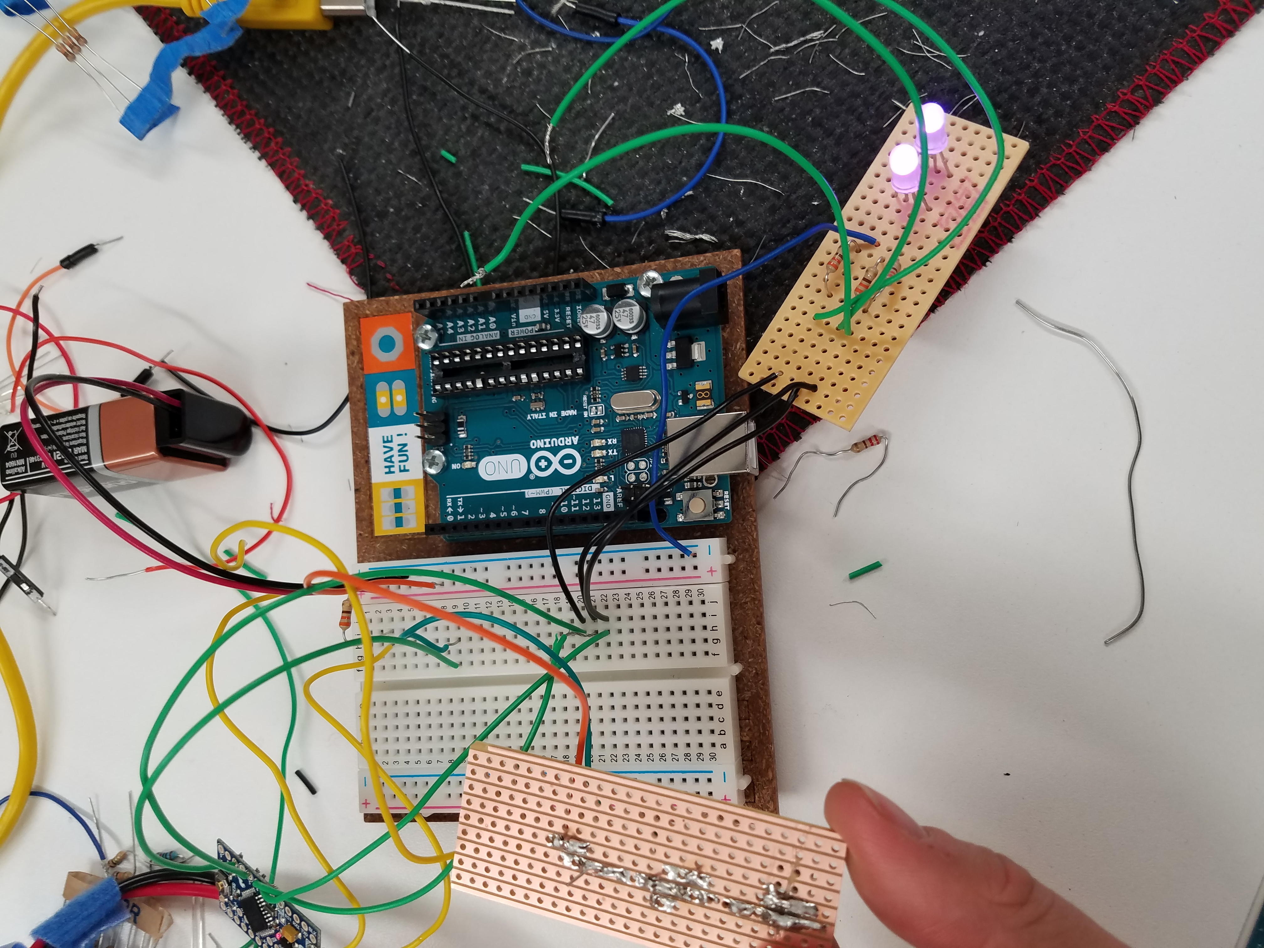
Here is a picture of the soldered circuit being powered through the breadboard. The color of the LEDs soldered onto the other board changes according to the orientation of the tiltswitch:
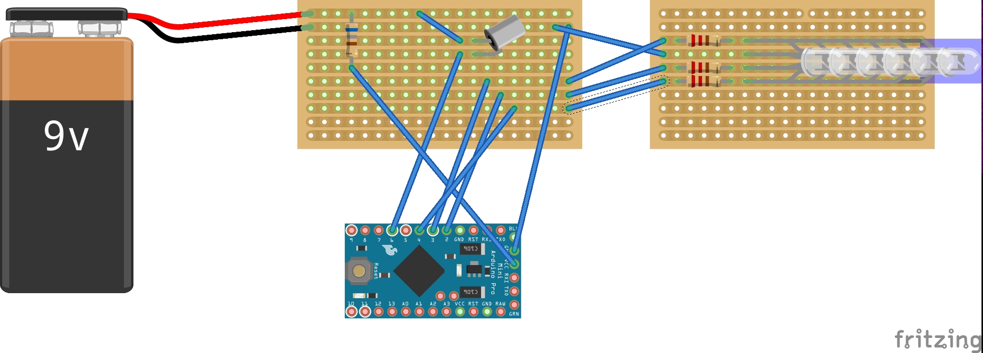
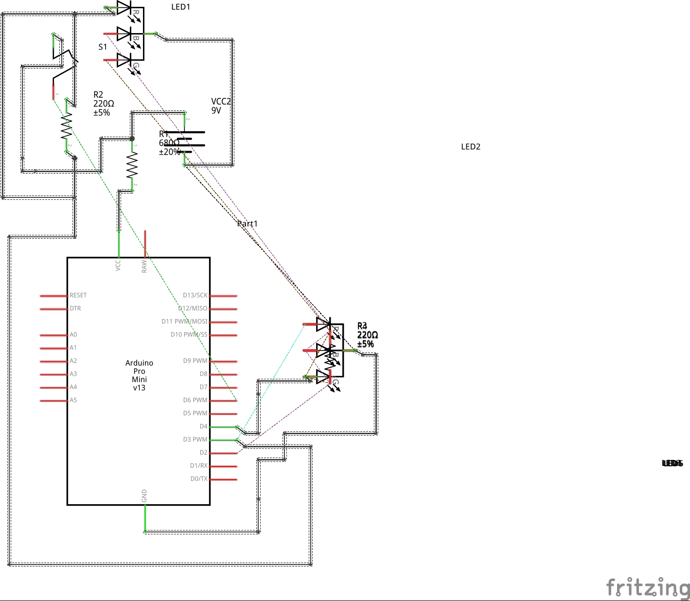
Here is a fritzing sketch and schematic of what the circuit looks like with only one stripboard with a row of lights.
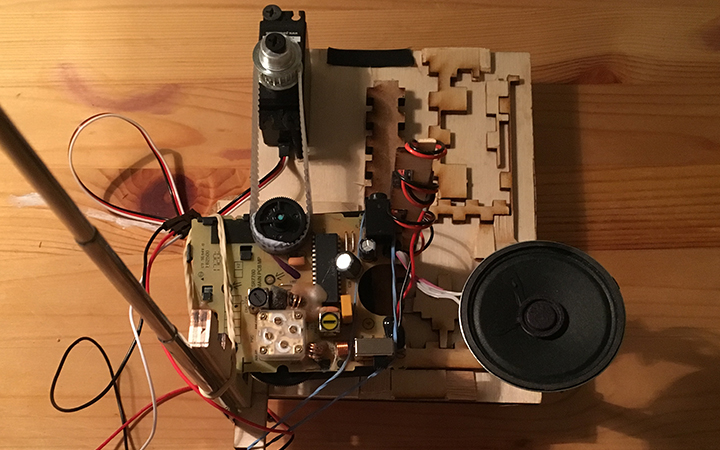
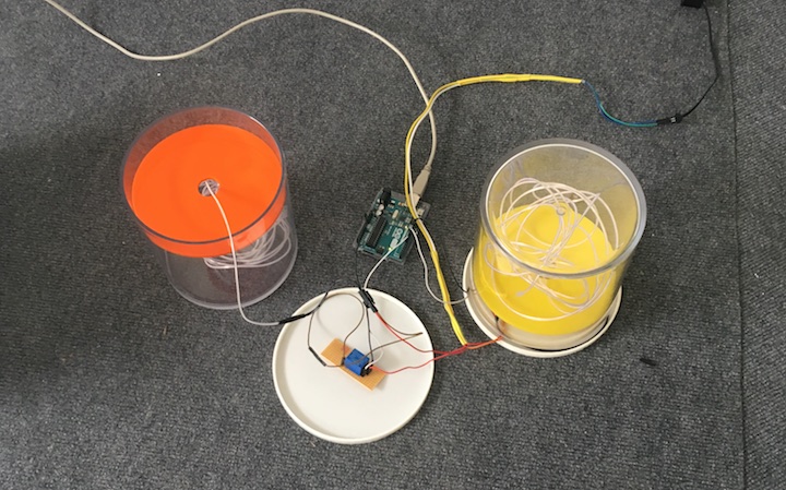
Because there were three different sections within the shoe, I wanted to have a PCB board with a row of lights in each section . Therefore, three different PCB boards would be connected to one another with wires. The video below shows what this circuit looked like outside of the shoe. The tilt switch would be included on another PCB board. One leg of the tilt switch would be connected to ground. I wanted to use the PCB board because I thought that it would be easier to create more contained circuits because the layout of the board provided me with more freedom than the stripboard.
However, I soon encountered a few technical difficulties with implementing this. First of all, soldering on the PCB board turned out to be quite difficult. I ended up using large chunks of solder in order to connect everything. I believe that the soldering affected the connections between the various pins and wires and prevented the circuit from working properly. The video below depicts the problem I encountered. In this case, when upright, the lights are supposed to be red, when upside down they are supposed to be green.
Red and Green Lights Not Working from Julia Makivic on Vimeo.
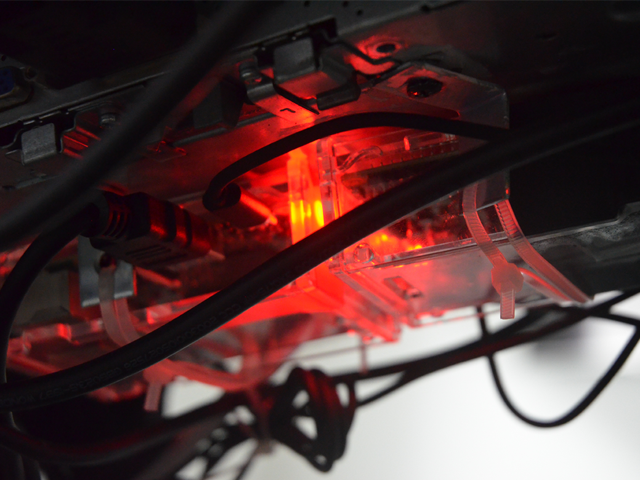
When I put the circuit in the shoe, I encountered even more problems because the wires were being squished and twisted, which was affecting the connections between various elements in the circuit. When the shoe was upright, it would display the correct colors, when the shoe was upside down, no lights would shine at all.
I decided to redo all of the soldering onto stripboards instead of PCB boards. Soldering on the stripboards was much easier and the circuit worked much better. However, I still encountered issues when I put it inside of the shoe. Whether or not the shoes switched colors was not always consistent. In some cases it took a quite a while for the shoe to become green when turned upside down and other times it would turn green only after some light shaking or jiggling.
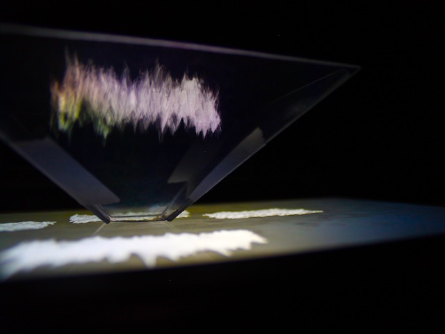
In this case, the lights are supposed to be blue when the shoe is upright and green when it is upside down.
This video shows that it takes a long time for the shoe to change color.
However, I took the shoes to the pole dance studio in order to try them out. Although, at first they worked rather well with the lights changing from blue to green if the were upright and turned upside down, as time went on, their performance became gradually worse. Although one shoe still switched from blue to green, how long it took it to switch was never consistent. The other shoe didn’t show any light when it was upside down. After a while, it stopped showing any light at all. Clearly, the connections within each of the circuits were very delicate and became worn out if they were moved or shaken too much.
Here is a video of me testing these shoes out in the studio. The top shoe is green because it is upside down. The blue one is upside down, but the lights are flickering as I pull it closer to me, indicating that something is not quite right with the wring.
Blue and Green Lights from Julia Makivic on Vimeo.
I decided that connected those rows of LED lights was far too complicated. As I could see from simple tests with the breadboard and the above tests on the stripboard, the circuit works well when there are far fewer lights. Therefore, I chose to see how I could simplify my circuit.
I ended up ordering some programmable LED light strips from Adafruit. Rather than requiring three pins for each color, there is only one pin for each light strip. Therefore, I wouldn’t have as nearly as many wires taking up space in the shoe.
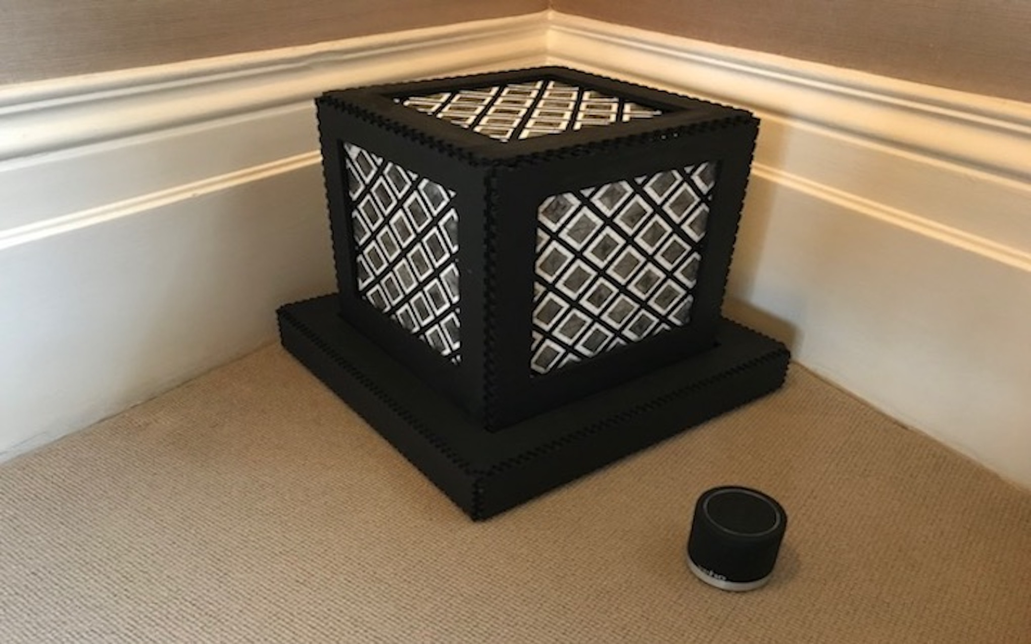
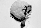
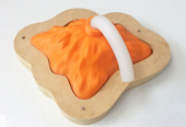
Here is a picture of the lightstrip that I used:
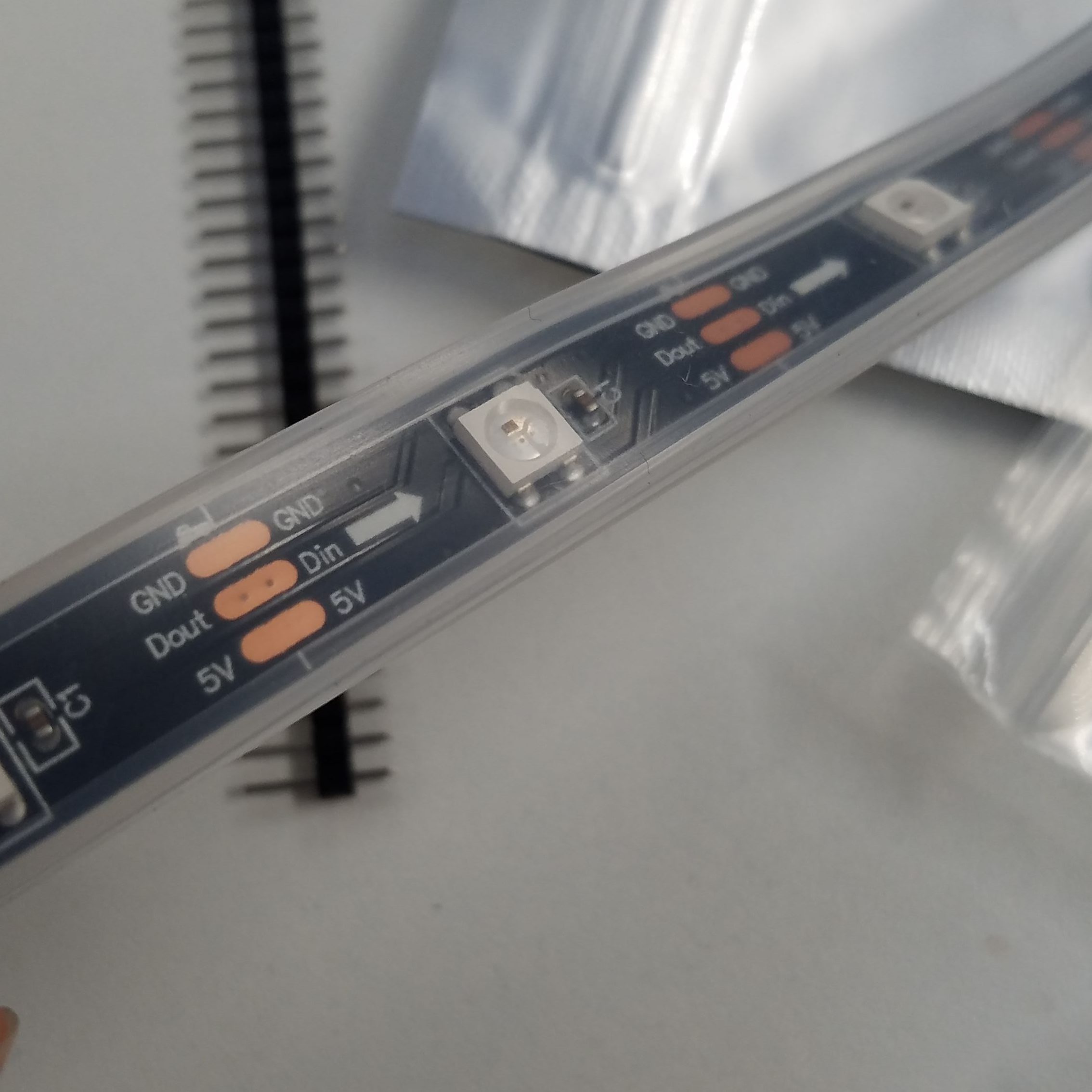
I needed to download the Neopixel library in order to program the colors for the light strip. The code for the LED light strip assigned a color to each light in the strip by looping through an array. While the tiltswitch was upright it flashed through a series of red toned colors. When the tilt switch is upside it loops through a series of blue toned colors.
The lightstrips were able to fit very easily inside each shoe. The color changes based on whether the shoe was upright or upside down were quite smoothe.
Working at Last! from Julia Makivic on Vimeo.
I was able to take the shoes to the studio and have some fun with changing colors.
Pole Final 3 from Julia Makivic on Vimeo.
Final Video 1 from Julia Makivic on Vimeo.
I am glad that I was able to make something I could use while dancing for this project! If I were to expand this idea, I would try to include sensors that took into account speed and also whether the shoes were lying on their side instead of just upright or upside down. I would also try to experiment with more elaborate light patterns.