


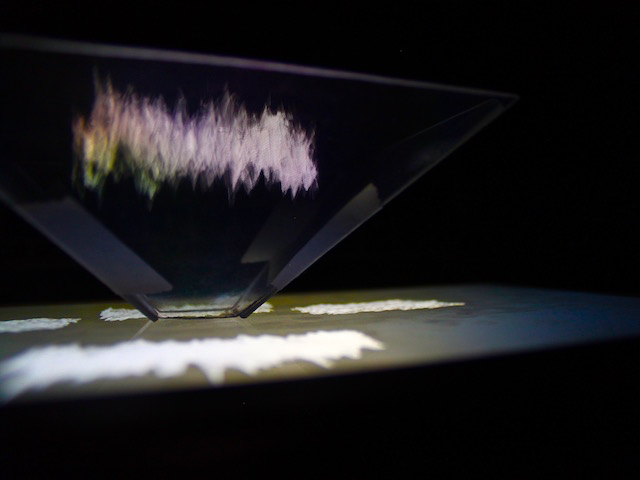


Braitenburg Vehicle
Braitenburg vehicles are one of the simplest examples of biologically inspired robotics. They use simple connections between sensors and motors to produce seemingly complex behaviour. This robot uses connections between photoresistors and geared DC motors to show fear and aggression behaviours.
produced by: Claire Fleischmann
Physical Computing Term 1 project - Braitenburg vehicle
Braitenburg vehicles are one of the simplest examples of biologically inspired robotics, an area I have a big interest in. They use simple connections between sensors and motors to produce seemingly complex behaviour. Braitenburg vehicles are something I am very familiar with and often run schools’ workshops where pupils write the code for them on the Lego NXT platform, however, I have not built one from scratch before and felt this would be a useful task to get familiar with 3D fabrication techniques.
The vehicle produced for this project connects two photoresistors to two geared dc motors. Two push button switches are also used; one to switch the vehicle on and off and the other to switch between two states (fear and aggression). The sensor-motor connections can be set up in two ways. In both cases increased light on the resistor results in the motor turning faster.
- In the first state (fear) the sensor on the left is connected to the motor on the left and the sensor on the right is connected to the motor on the right. A vehicle set up like this will speed up when exposed to more light and tend to turn away from a light source.
- In the second state (aggression) the sensor-motor connections are crossed. Now if the light source is to one side, the vehicle will turn towards it with increasing speed. This is the most interesting state for interaction as the robot will follow a moving light source.
The intention is for the user to hold a light source to interact with and control the overall direction of the robot.
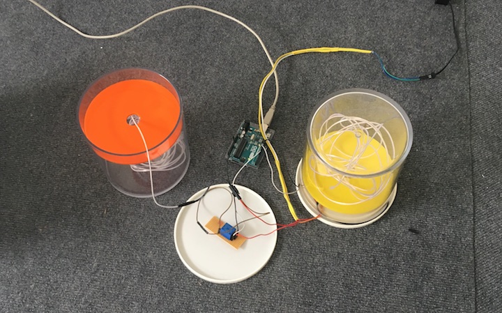
Connecting the Photoresistors to the DC motors
One side of each photoresistor is connected to power and the other side to ground via a 10 kilo-ohm resistor. The voltage at the point where they meet is proportional to the ratio of their resistances; as the amount of light hitting the photoresistor changes, its resistance (and the voltage at this junction) will change too – this voltage is measured by connecting the junctions to the Arduino Analog pins A0 and A2. The voltage (a value between 0 and 1023) is then mapped to the pins controlling motor speed (a value between 0 and 255).
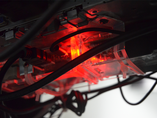
This project uses a H-bridge to connect the motors – this is not strictly necessary as the direction of the motors is never changed, but I wanted to build in the potential for further control later on. Pins 1 and 9 of the H-bridge are connected to digital pins 9 and 10 on the Arduino – these are the enable pins that turn the motors on and off. H-bridge pins 4, 5, 12 and 13 are connected to ground. H-bridge pin 16 is connect to the 5V power on the Arduino and H-bridge pin 8 is connected to a 9V battery. The motors are connected to H-bridge pins 3, 6, 11 and 14. The direction of the motors is controlled by H-bridge pins 10 and 15 connected to Arduino pins 5 and 6 (right motor), and H-bridge pins 2 and 7 connected to Arduino pins 3 and 4 (left motor).
Connecting the switches
The switches are connected to the Arduino digital control pins 2 (on-off switch) and 7 (switch to change states). When a switch is pressed the circuit is completed and the digitalRead() on the control pin reads HIGH which toggles the state of a variable. Some code is included to debounce the switches – this was necessary as vibrations due to the motors resulted in false HIGH readings.
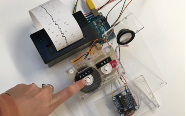
The prototype
The initial breadboard prototype used only one switch to turn the motors on and off but can be seen to be working in the video. The first assembled vehicle used dc motors with no gearing which did not produce enough torque for the robot to move.
Fabrication
The robot chassis was designed in TinkerLab and includes mounting holes for the photoresistors and the Arduino Uno. It also uses two parts sourced from Thingyverse:
The wheels were adapted from Arduino Robot Chassis (Servo). The adaptation added an axle to enable the wheel to fit on to the motor.
.stl files were exported to slic3r to generate G-code for the printer. The G-code was loaded into Macpronterface and the robot chassis and wheels were 3D printed using a Printrbot Simple Metal.
Components were soldered onto protoboard
Reflections
The robot works; however, a considerable amount of tuning (depending on the physical space available and ambient light conditions) is required to facilitate a rewarding user interaction. The wheels also need the addition of elastic bands to get sufficient grip and the robot is currently still tethered to a 5V power supply. I also feel that given more time I could have done more with the appearance and enclosed the electronics.
Setting up circuits on the breadboard with the Arduino is something I am very comfortable with but I have not soldered before and had no experience with 3D printing or laser cutting. Getting familiar with the software to produce the stl took some effort and the Printrbot Simple Metal took a great deal of time to master – the bed on the printer I was using is not level and because the print was quite wide I had to calibrate the z-offset of the hot end to a compromise where at one end of the print the individual cylinders were not laid down as close as I would have liked but at the other end I needed to minimise the degree to which the hot end would drag through the print. I spent many hours with video tutorials for both Tinkercad and the printer and have now been nicknamed the 3d-printer-whisperer at work.
I feel this project has been challenging in terms of the build but I feel I have learned a great deal to take forward to next term.
References
Debounce code adapted from https://www.arduino.cc/en/Tutorial/Debounce