


PIXEL BLAST
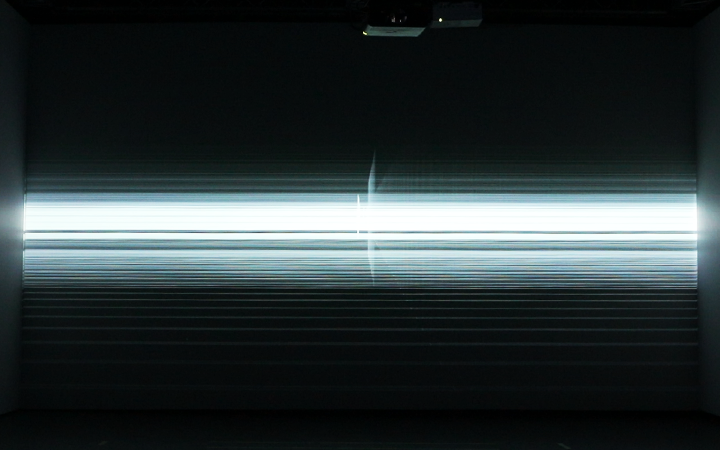
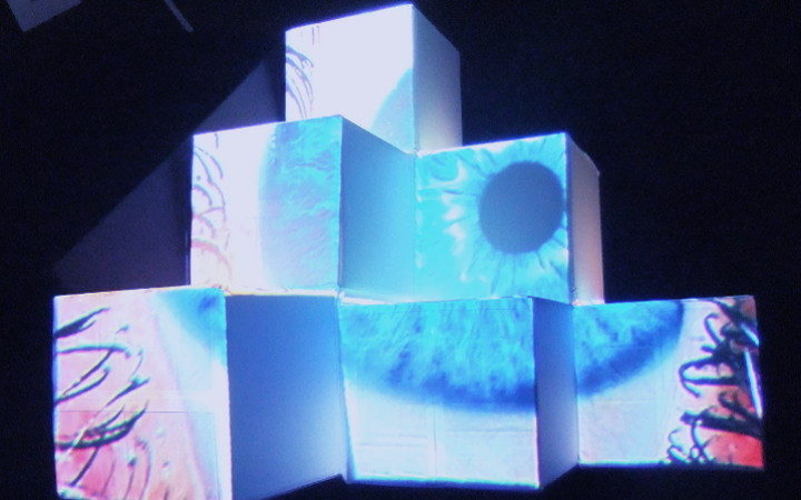
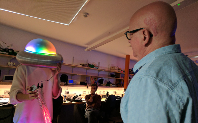
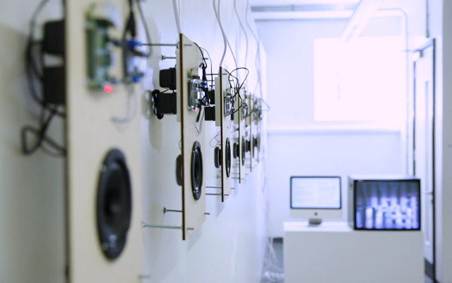
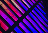
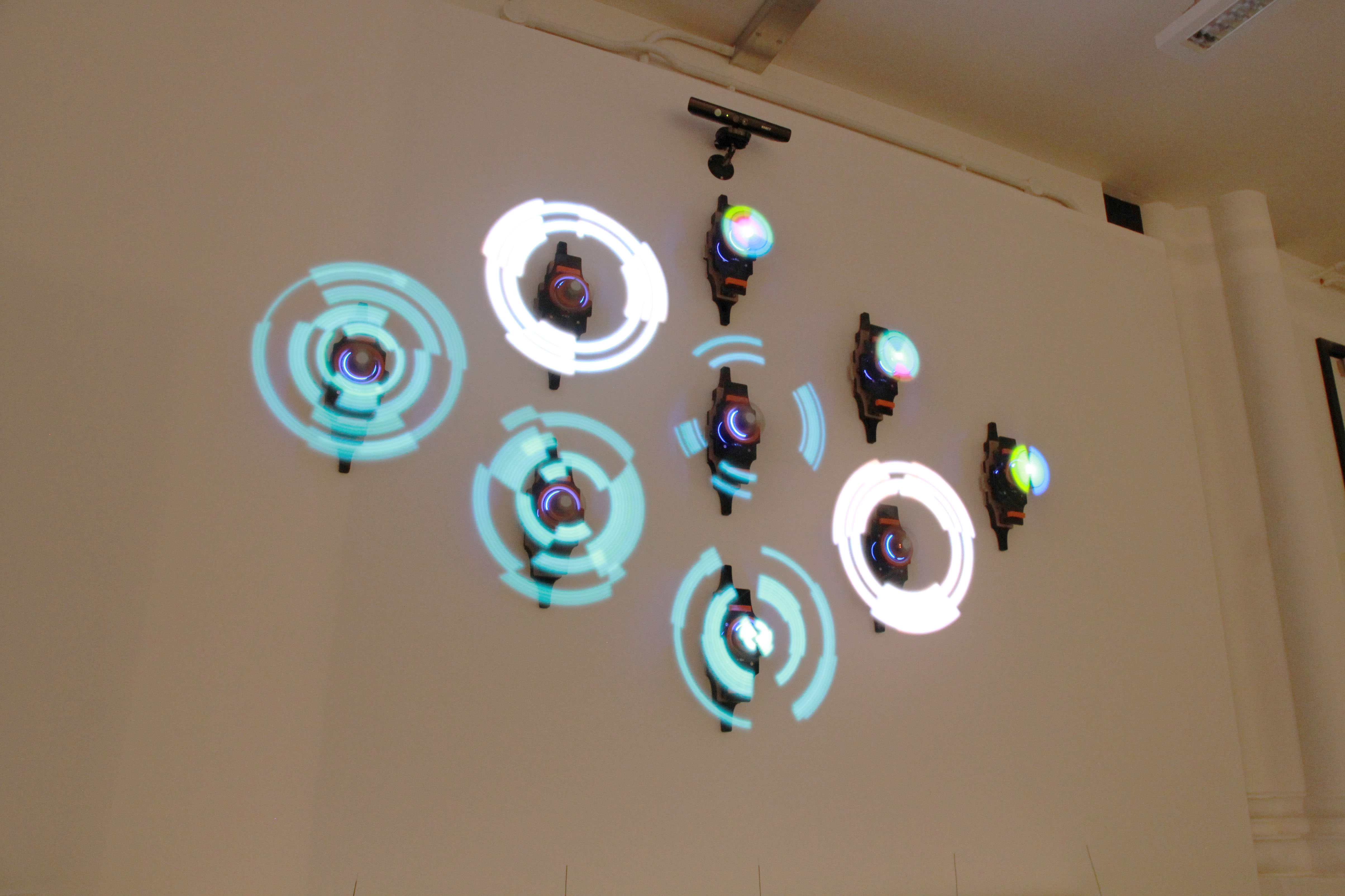
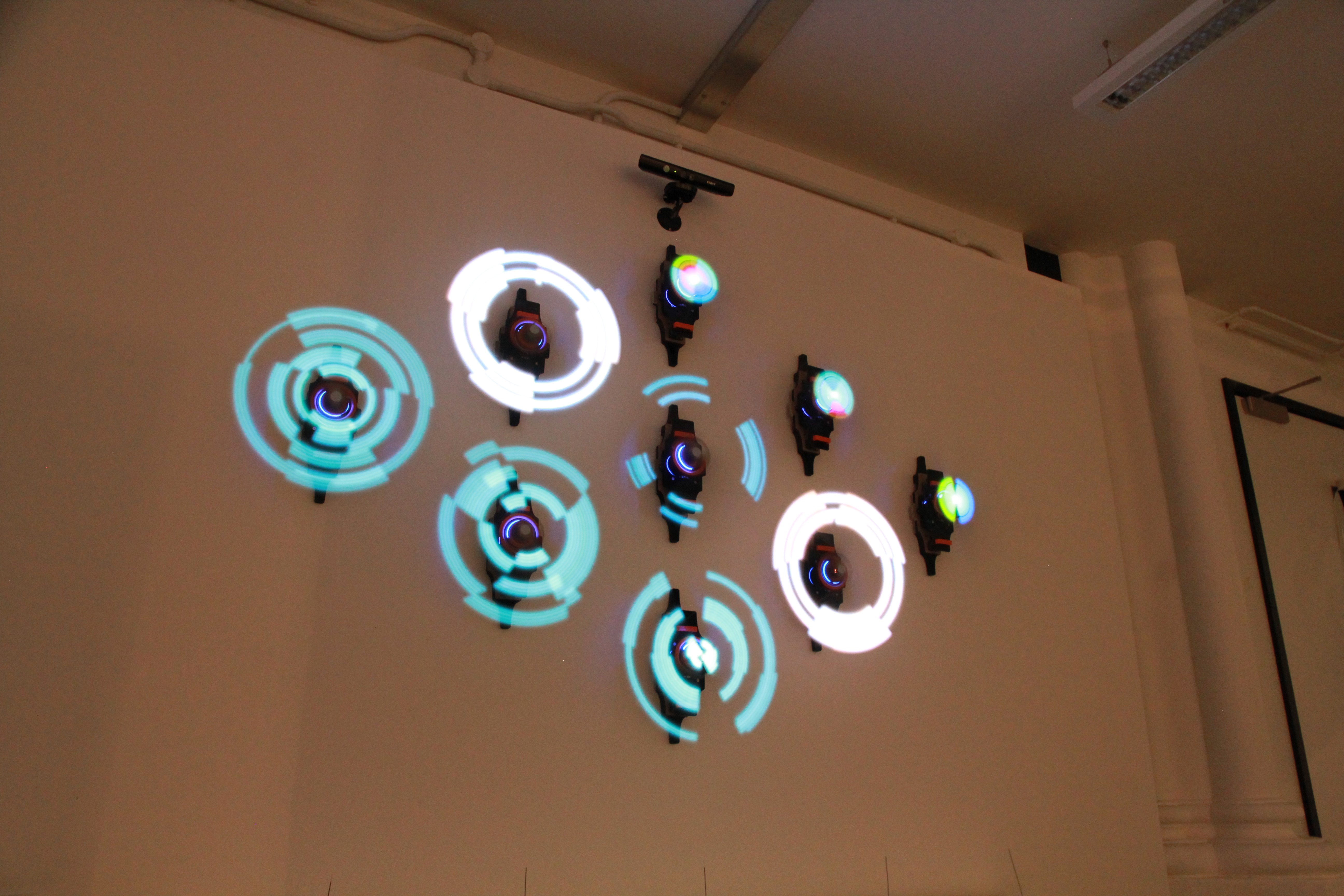
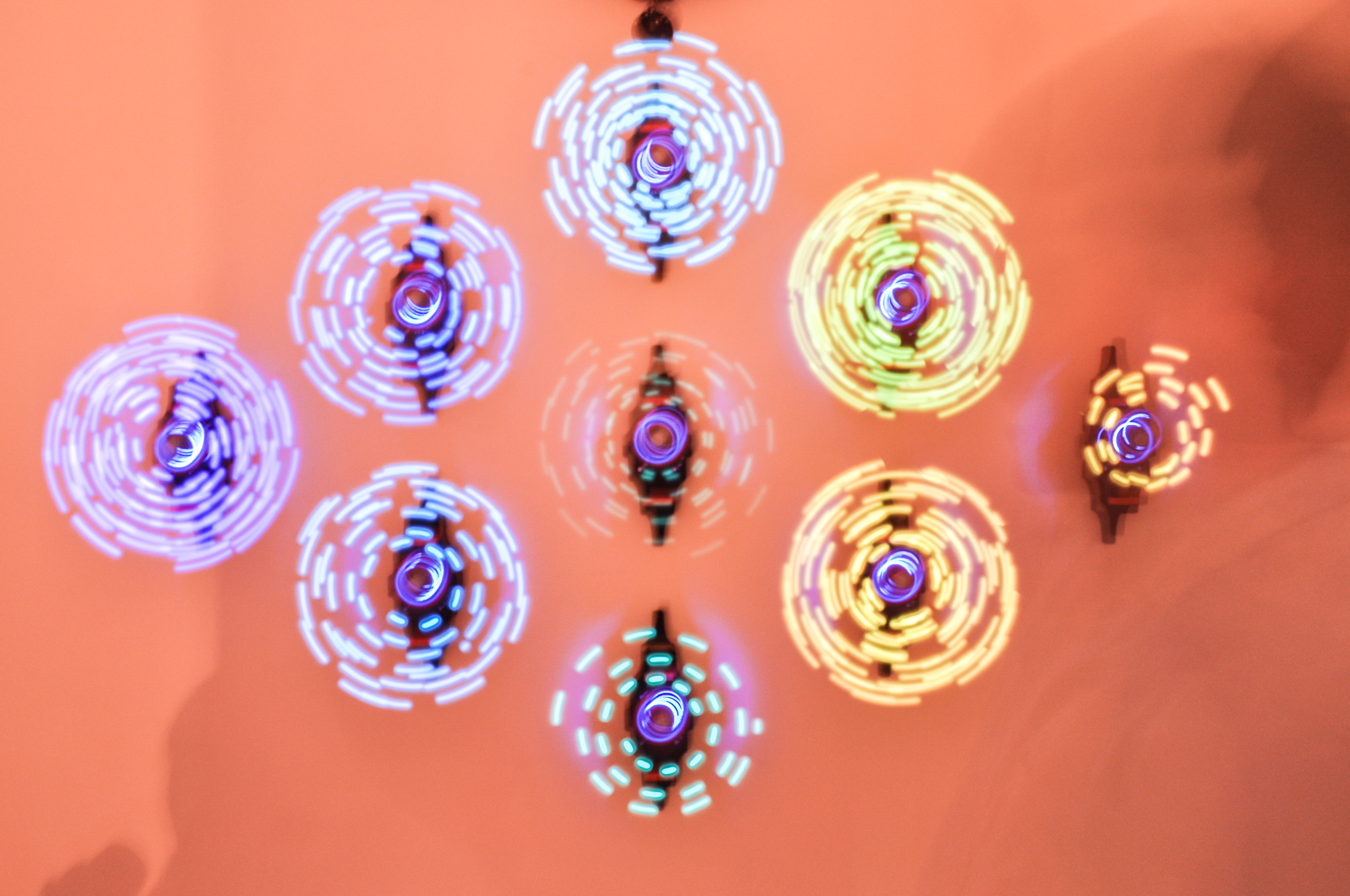
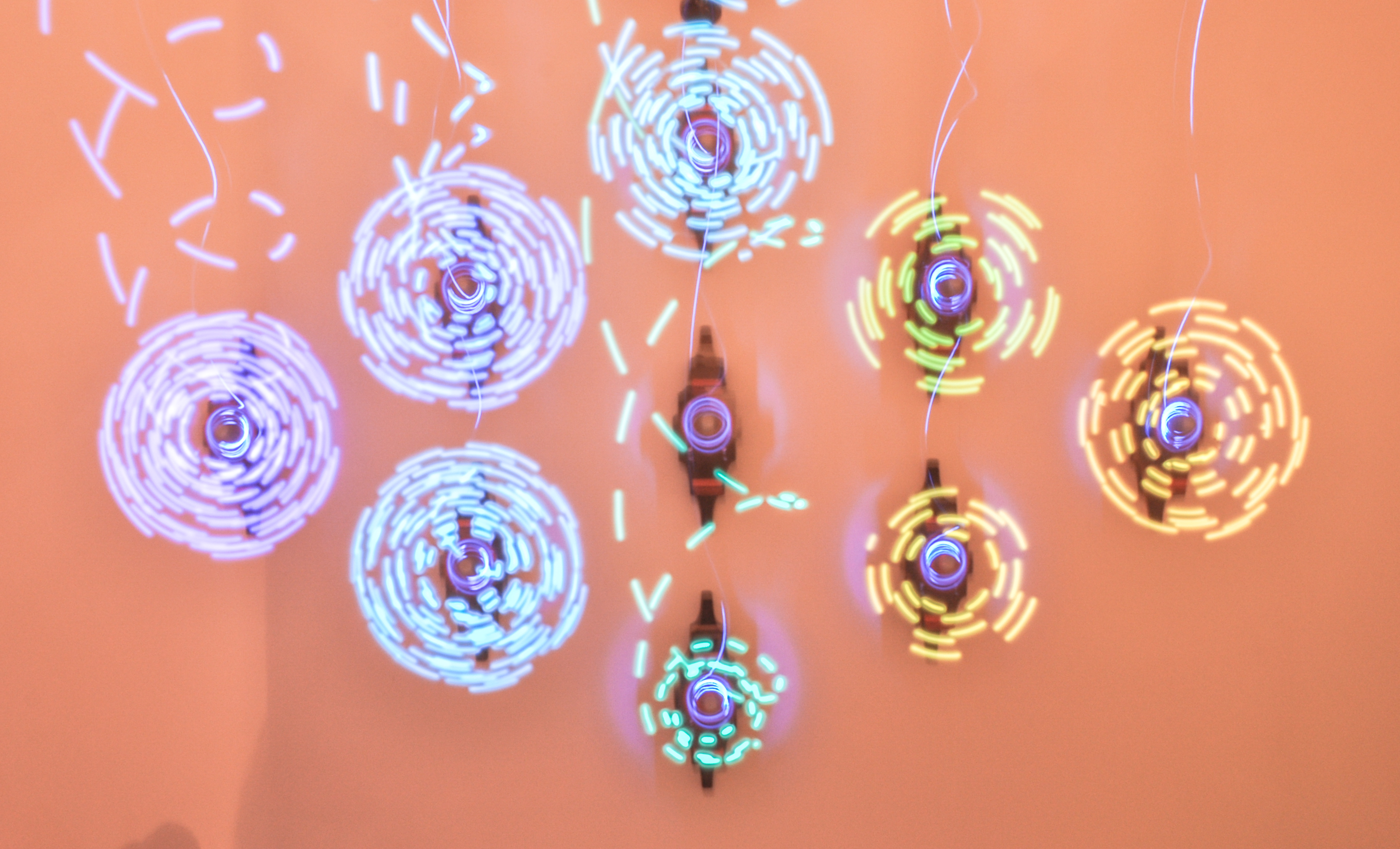
Pixel Blast is an interactive installation made up of nine 'Persistence of Vision' displays which come together to create hologram-like images. This project challenges the idea of what a screen has to be, presenting something far more rich than a computer display.
produced by: Natthakit Kangsadansenanon
Introduction
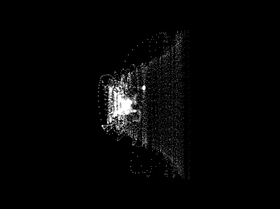
The artist tracks the audience's movement using a Microsoft Kinect. This human awareness contextualises the visual image, linking it back to the viewer. The unison of all nine units working together brings a harmony to this larger system, enveloping each individual unit and it own unique characteristics. This project seeks to explore forms beyond the traditional screen through this collective output. By then feeding back the real world, the artist gives us a glimpse of a bold visual reflection and of a possible future.
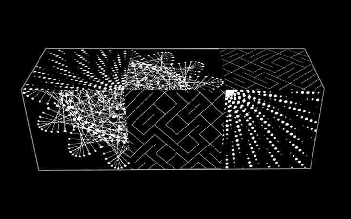
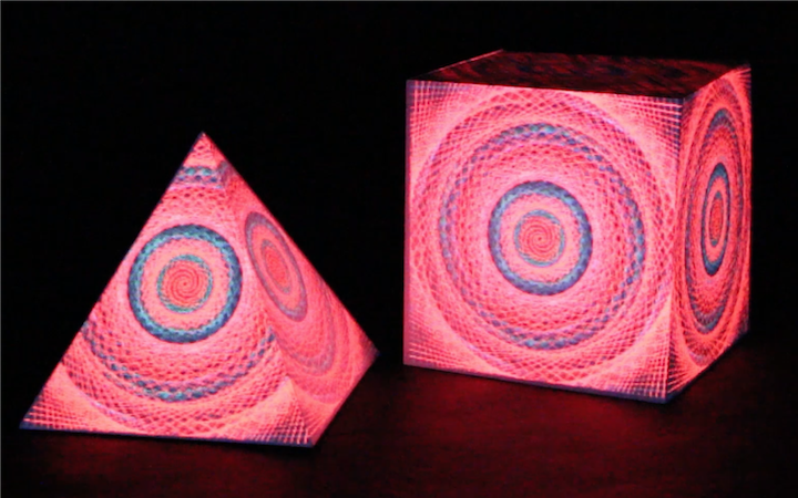
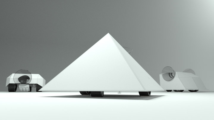
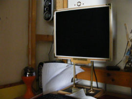
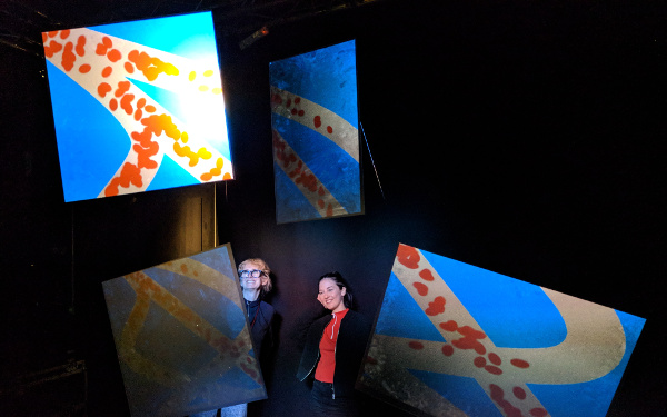
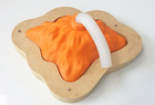
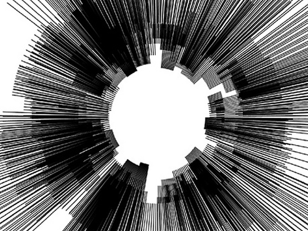
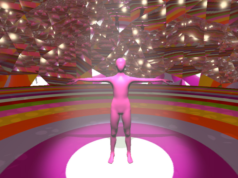
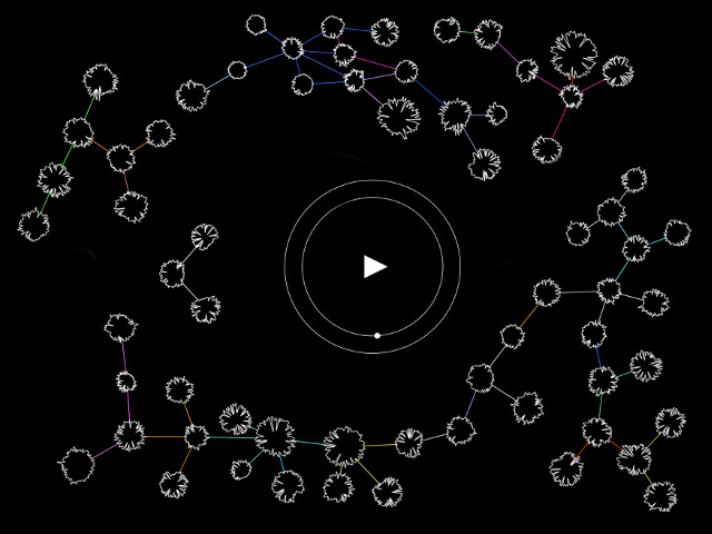
Visualization of my first concept design
The Journey
Building an interactive wall has always been my goal since the start of this course as this wonderful journey simply began and inspired by the work of Daniel Rozin (the mirror guy). As months passed by, my idea had constantly crystalized and transcend into even more practical procedures that transformed an abstract plan of installing interactive aspects on the wall into seeking, exploring, and experimenting on visible interactive units and components. At this tense period, a moment of pure fascination occurred when I encountered this thing called POV display. The reason was that the image I perceived seemed to be floating in the air in a very mesmerizing and attractive fashion. As such, I kept researching to understand its operations and how to incorporate my idea and creativity into its mechanism. The pivotal point was when I found an instruction website for DIY projects which significantly boosted my confidence to start putting pieces together. With such confidence and being ahead of schedule, I decided to spend the last four month (starting from June) prior to the final submission to try innovative things that can push this project even further from any traditional techniques and systems. This was what I proposed: a vertical spinning up and down LED strip instead of angular rotation which is an approach I haven’t encountered or in anyone’s work in the online community. Therefore, I wanted to build 25 of them. This is quite bold move at a time to go in front of the room and say what I am planning to accomplish. I could imagine how wonderful the result is going to be but the more I’ve got my hands on it and the more I’ve understood what is required to make this spinning panel operational is much more complex than I anticipated. Hence, it became quite a struggle as the deadline was approaching while nothing physical is being assembled at all. This dilemma and the time constraint forced me to adapt for something which could guarantee that the project will be ready and working on the exhibition date.
Despite such, the situation was not a setback at all. It was more like a gentle tap on my shoulder, whispering an alternative that I could approach this project more traditionally on this display first, and once I’ve managed to fully understand the nature of the simplified version of this software and hardware, then I could take this back from the shelf and realize my idea of displaying an interactive the 3D images as illustrated above.
Late June, no more time for dreaming, the physical thing need to be made no matter what. At this point, I have enough knowledge of the components required to build the unit but the design cannot be copied and pasted from the internet due to its size and performance to accommodate an exhibition. So the internet giving enough to start this journey but I need to carry myself from the second step to the ends. I adopt trial and error method to approach this journey, there are a lot of error along the way but ultimately it is a good lesson for me learn to finish the project. There are a lot of problem that I did not beware to solve at the start of the journey and that is the beautiful of this path.
Technical Challenge
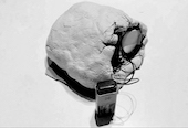
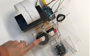
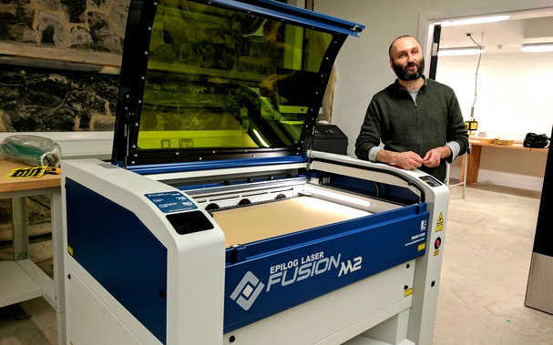
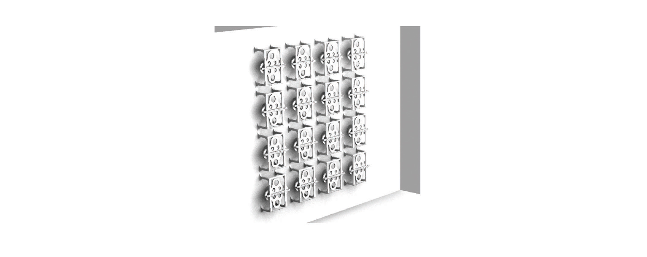
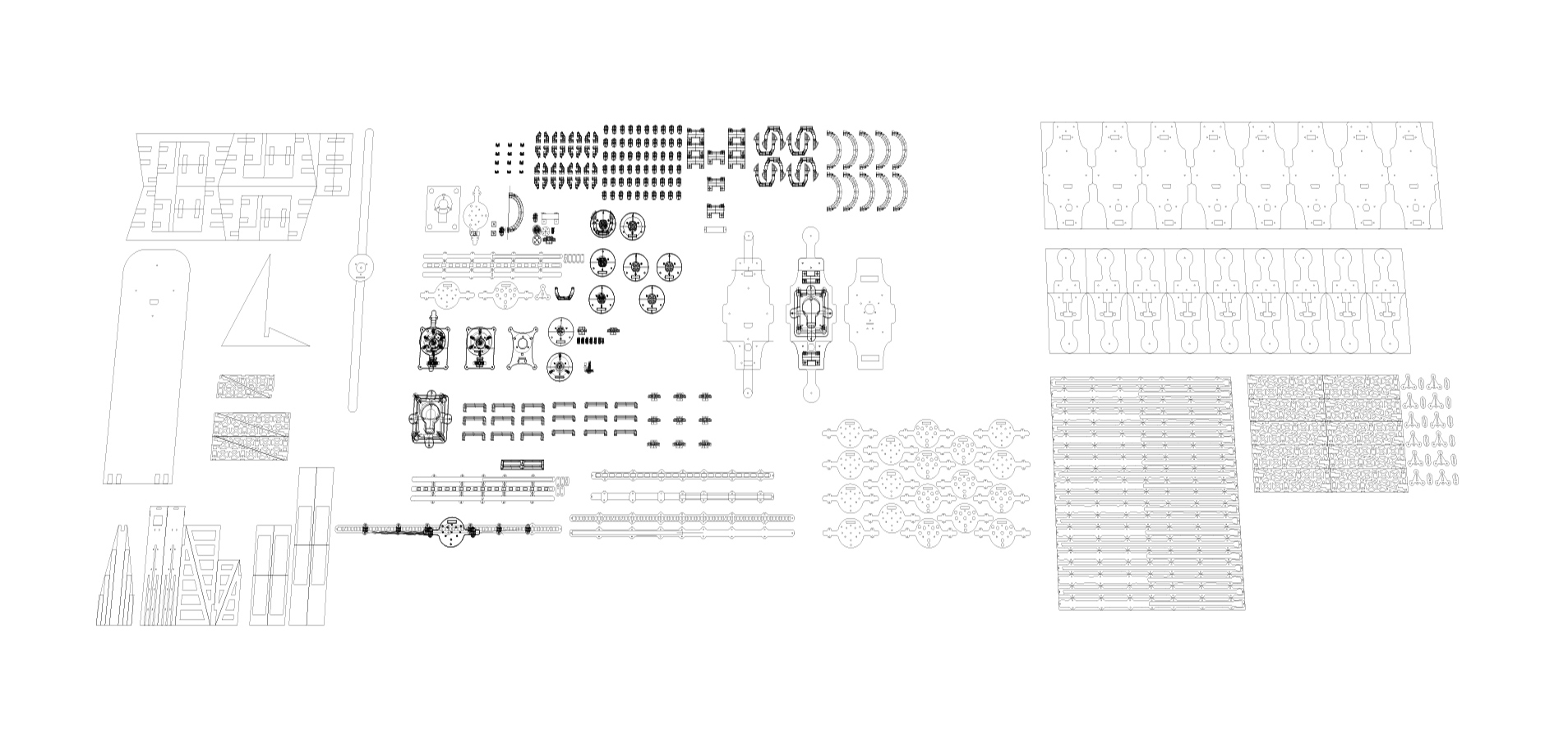
My first step was to look for the right motor, the one with enough speed to rotate the LED strip and affordable price-wise. The answer was 12V brushless DC motor. At this point, I needed to design the enclosure for this motor to house it vertically on the wall, I used Rhino 3D software to design parts and then print it from Ultimaker 3D printing machine. The PLA material is strong enough to carry the motor, so I trust this machine to produce a lot of parts for my design. Another machine that I relied on is laser cutting machine to shape some Arcylic and other sheet materials up. To put it simply, I attached the 3D file shown above, right there you can see many difference version of the same components, and printed them. After I found the right motor, I needed to look for the microcontroller and LED strip.
I chose Arduino Nano because of its size and performance capacity. On the other hand, LED strip is not that easy choose. There are many options in the market and it required some research and testing it in the real setting. Hence, the selection and testing process is costly and time-consuming but at least I found the one that’s suitable for my performance expectation. I chose APA102: a fast Led strip, a spot-on match for this fast pixel changing project.
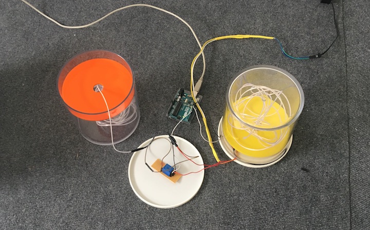
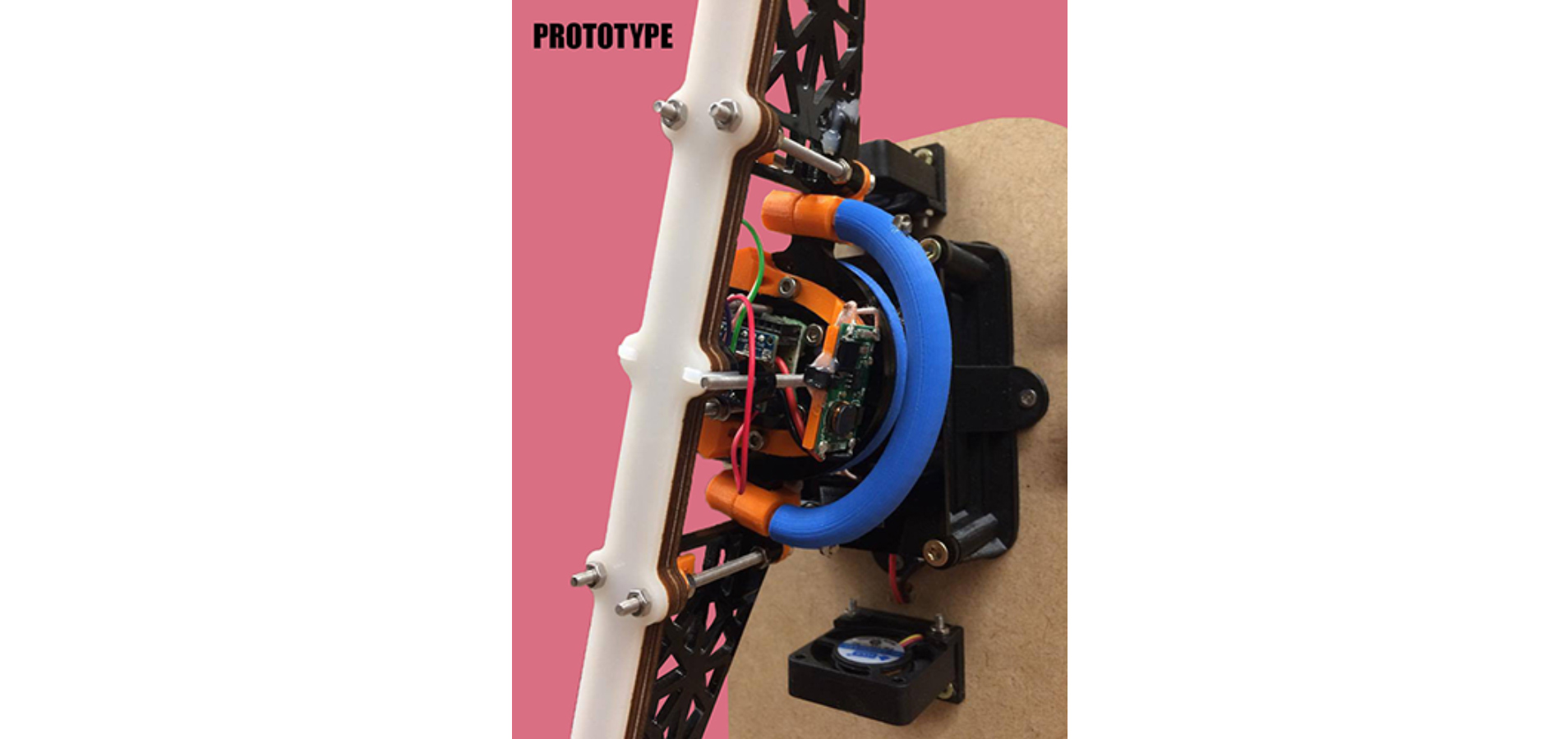
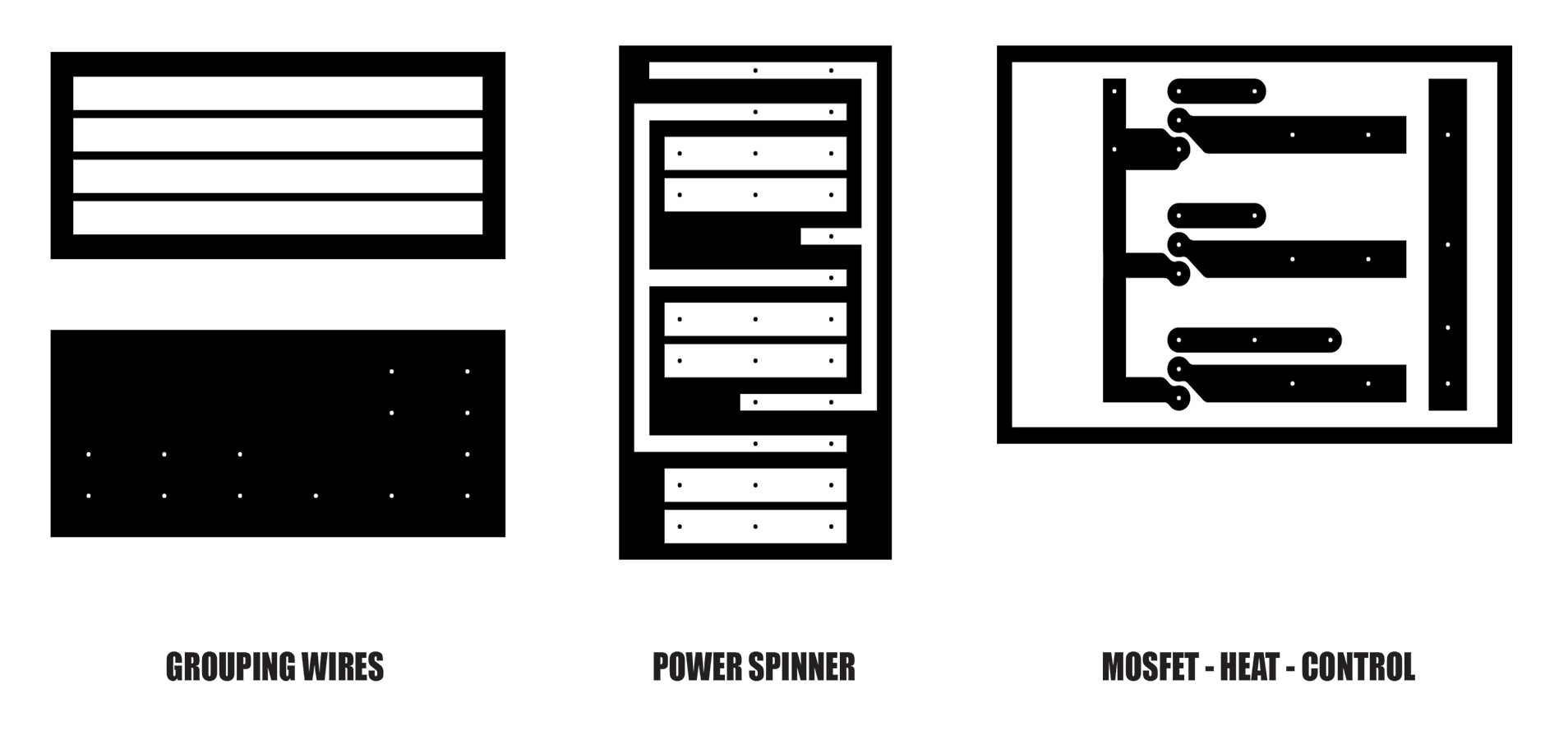
One of the most astonishing components on my design which I would call: a true game-changer is the Wireless charging. Powering something that rotates all the time is impossible by the traditional red and black wire. The first alternative was to include the ‘slip-ring’, a power supply that could potentially be the source of my project into the system. However, with trials and interesting findings, the slip-ring had proven to be unstable and its capacity was insufficient due to its overheating issue. This whole problem challenged me to innovate a new way to power the system. Going back from scratch, I decided to assemble a stable wireless power-supply connection between the piece, the power source, and the movements in range.
The issue of balancing a unit that spins non-stop can be the downfall of this project. As such, it is super important to maintain the speed and the overall structure, this necessitates me to design extra parts to counter-weight the Arduino Nano. I did this via 3D printing.
Other components are Hall sensor to detect the magnet, this way I know that the LED already rotate one round and I can program the function to trigger every time the sensor changing the state, this way I can program the pattern to show frame by frame.
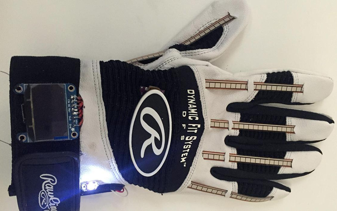
The last component to mention is 433HZ wireless receiver. My goal is to make an interactive wall, so it is the main requirement for the whole unit to synchronize with the changes and movements in range made by users and this change will determine the behaviors of each units.
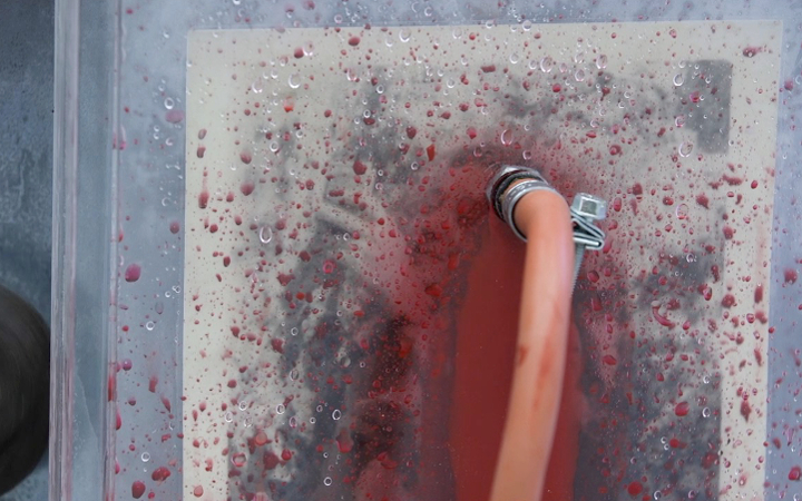
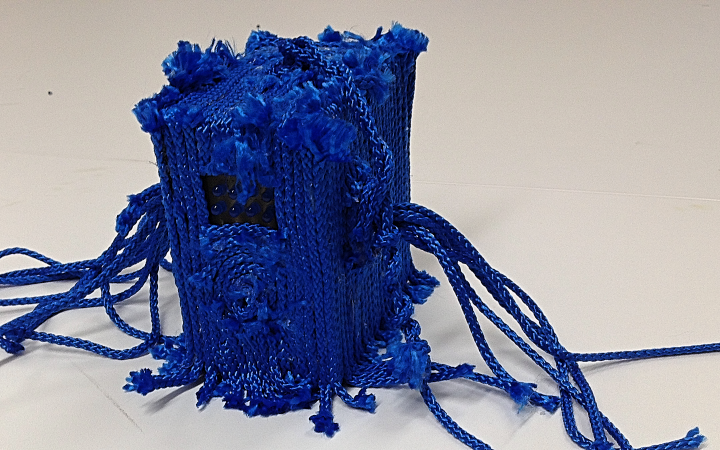
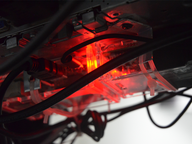
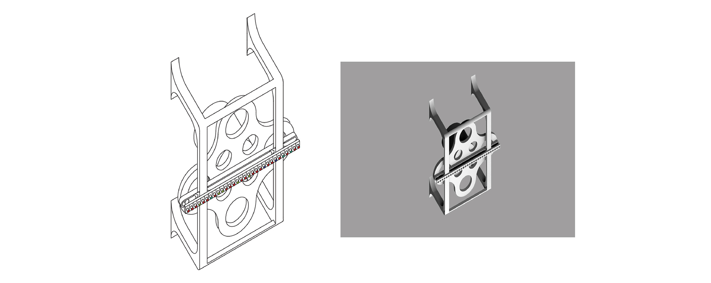
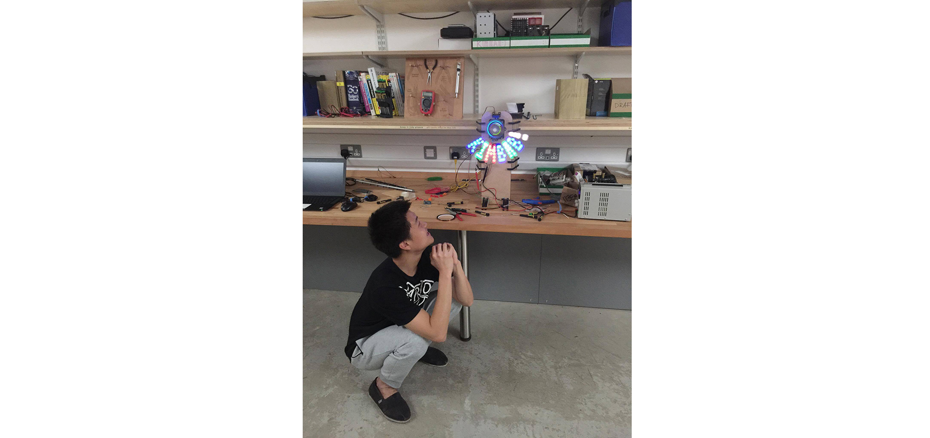
I think I do spend at least 2 months to develop the stable prototype. Fitting all of those components together is not an insurmountable task but it was very costly, time consuming, and quite discouraging mentally due to efforts exerted into many trials and configurations just to end up with technical flaws and systematic errors which drove me to re-work the whole process back from scratch multiple times to finally from the stable one (just like Musk’s SpaceX programs). The last image above is the test of my passion, the culmination of all errors, and the achievement of the hardware and software systematically synchronized and working together efficiently. With that achieved, mass production comes the next, it’s time to do more of this!
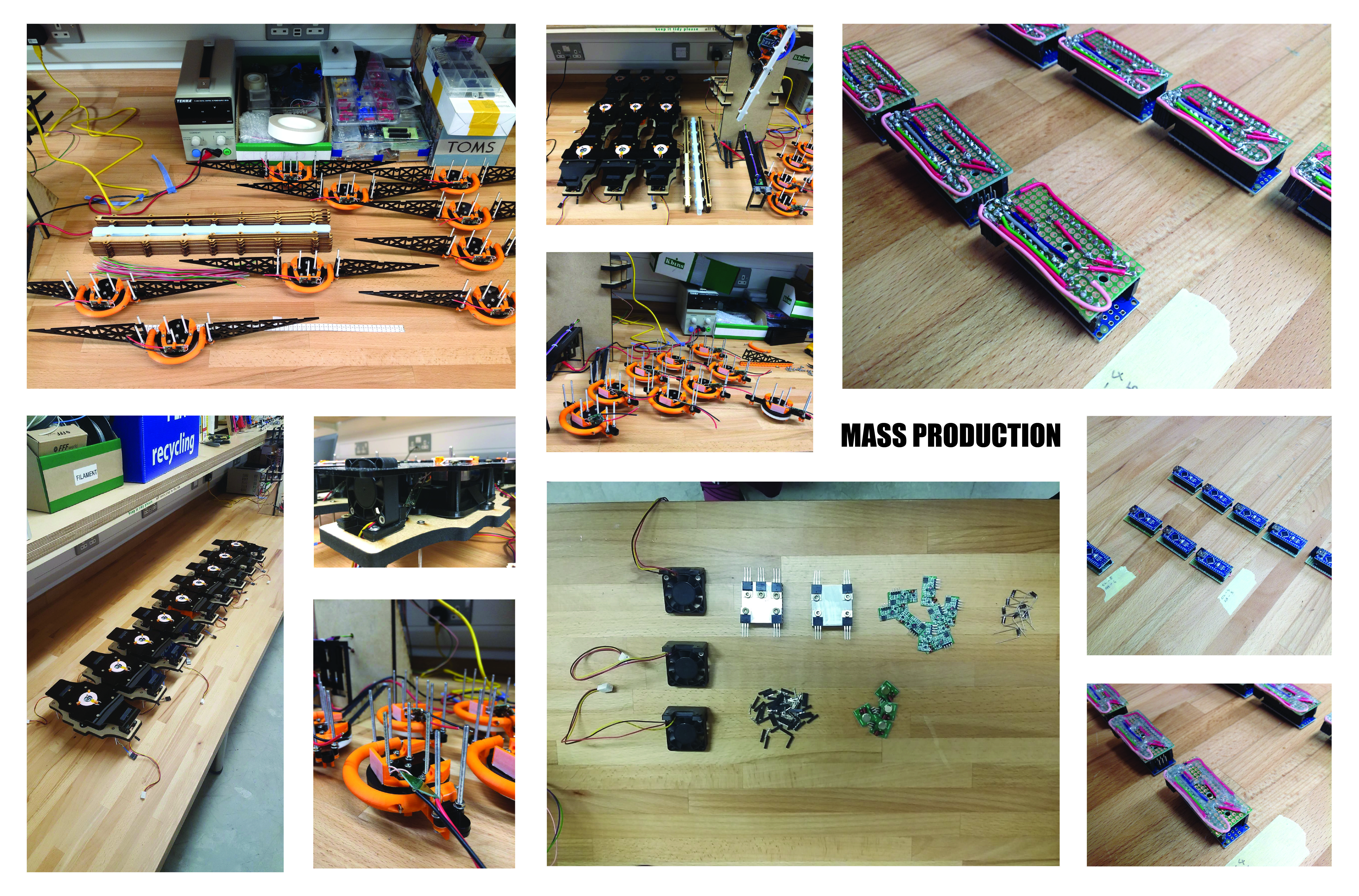
Mass Production
Why just make only one? My original plan is to build 25. However, the number gradually reduced to 16, and with financial and time constraints, the final number was just 9, sadly. On the bright side, that is still a lot anyway to repeat all the process for 9 times. If there’s any slight miscalculation or technical defects which occurred when the 3D printing made the slightest flaw and ended up printing different size that I did not assign, I would have to wait another day to assign the printing of the new batch. It takes two week to produce, assemble, test and repeat. Therefore, time management is as vital as the system’s knowledge and manufacturing and those are what I’ve learnt to make plan (as well as a lot of backup plans) and execute accordingly to finish the project on-schedule.
3 important learning points:
- There will always be defects so always prepare spare materials: if I prepare to do 9, I should at least prepare 12
- Time and accessibility is highly limited. The opening hours of the lab was the total hour that I can work per day. Furthermore, I am not the only one who would use the machines, so keep in mind that I won’t always have the accessibility. Therefore, time management and schedule planning is one of the most important priority for this kind of project.
- Make everything as precise as possible, from the framework, design, the system, and more importantly incorporating the know-how of problems prevention into the unit’s manufacturing process. This means that if any problems arise or parts that are not fully operational, I would have procedures and countermeasures in place which would be highly time-efficient as I did not need to think and fix arising problems arbitrarily without directions. With such plans in place, making 9 units become all about making the first unit, learn about it thoroughly, record ways to design and solve arising issues, then repeating the process 9 times (or as many as I can if there’s no time limit)
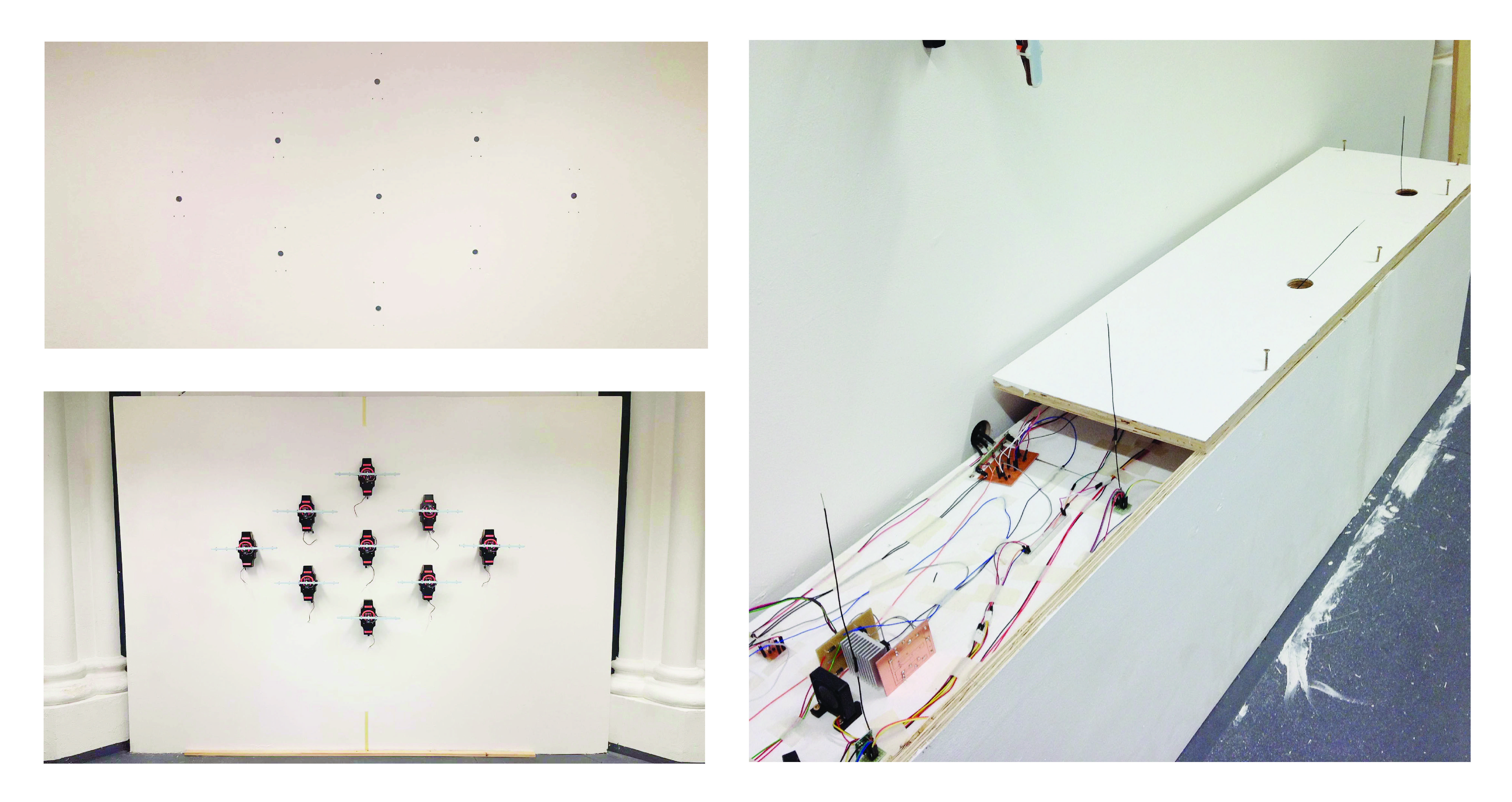
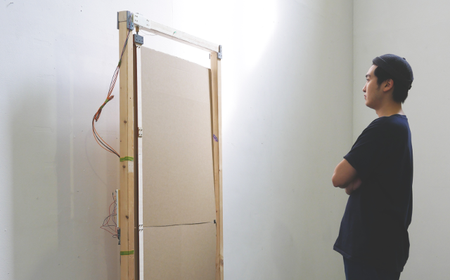
Installation Challenge
Settling for the right location for my project is crucial. Having 9 spinny things running at the same time require a solid wall attachment, nothing would be worse than a shaky wall or background that sabotages my installation. I managed to drill 9 big holes to conceal the power cables for each spinny units. Making the space as clean as possible is the priority. Below all these 9 units I make a long plinths to allocate the power supply and electronic parts hidden from eyesights.
At the top of the plinth, I drilled 5 holes for 5 transmitter modules antenna and air ventilation for the hot electronic part to running this project.
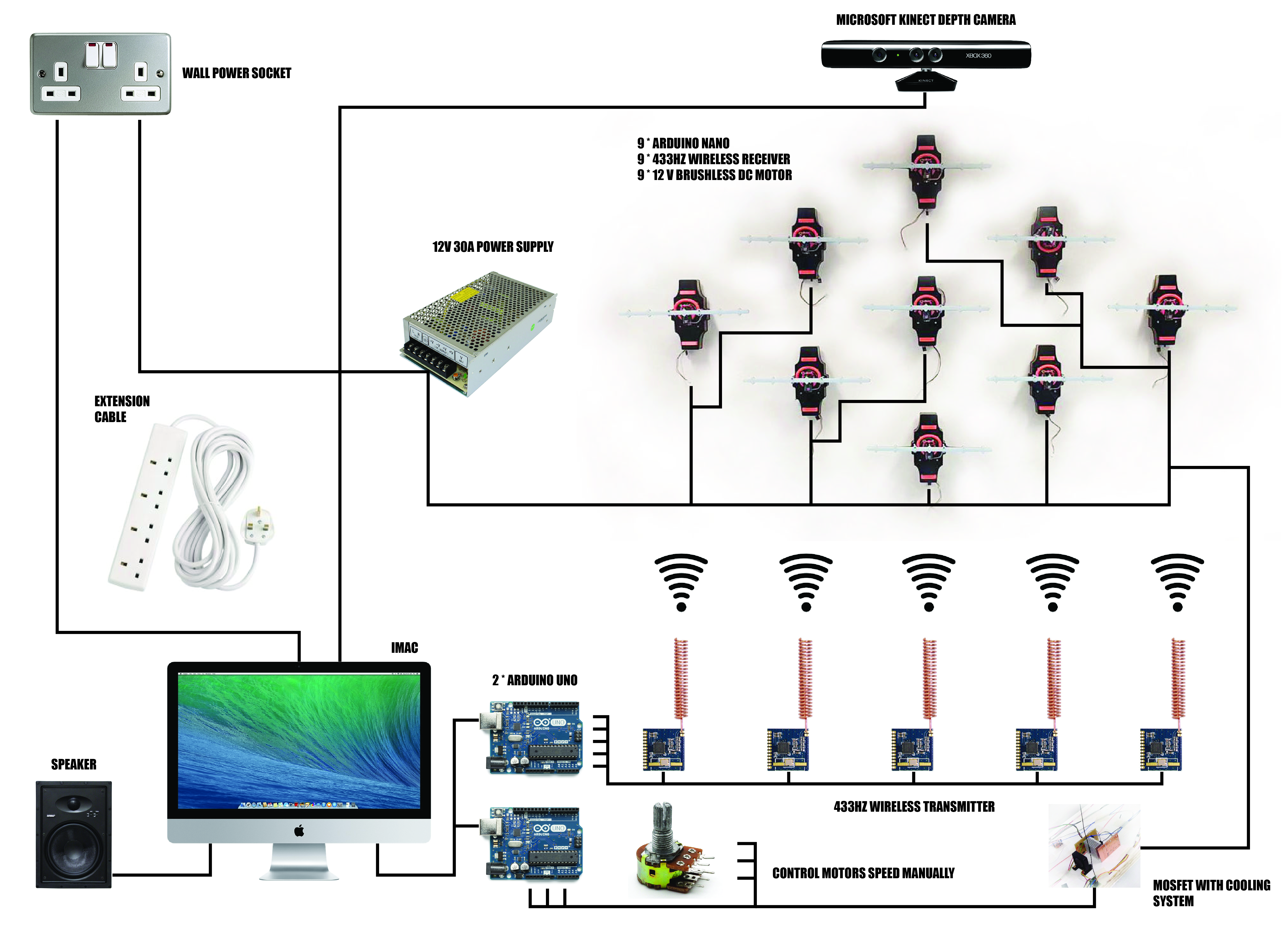
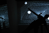
Communication Between Hardware
Kinect position on top to detect the movements that occur in front of it and separate into five columns. This data being send to the IMac which activate the wireless transmitter that attach to Arduino Uno to transmit the information to trigger the function of spinny units that are detecting people moving in its range. Once the transmitting is successful, it will trigger the speaker to turn on the sound and the moving shape of LED light on the spinny unit. I also have the separate Arduino to control the speed of all of this 9 units.
Self evaluation
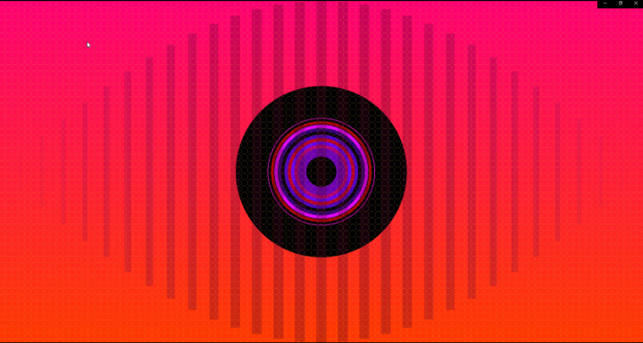
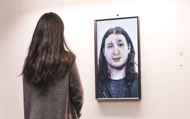
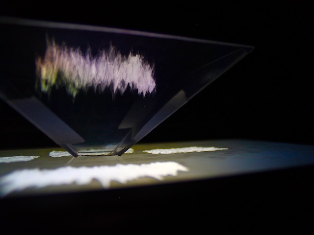
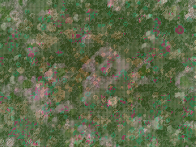
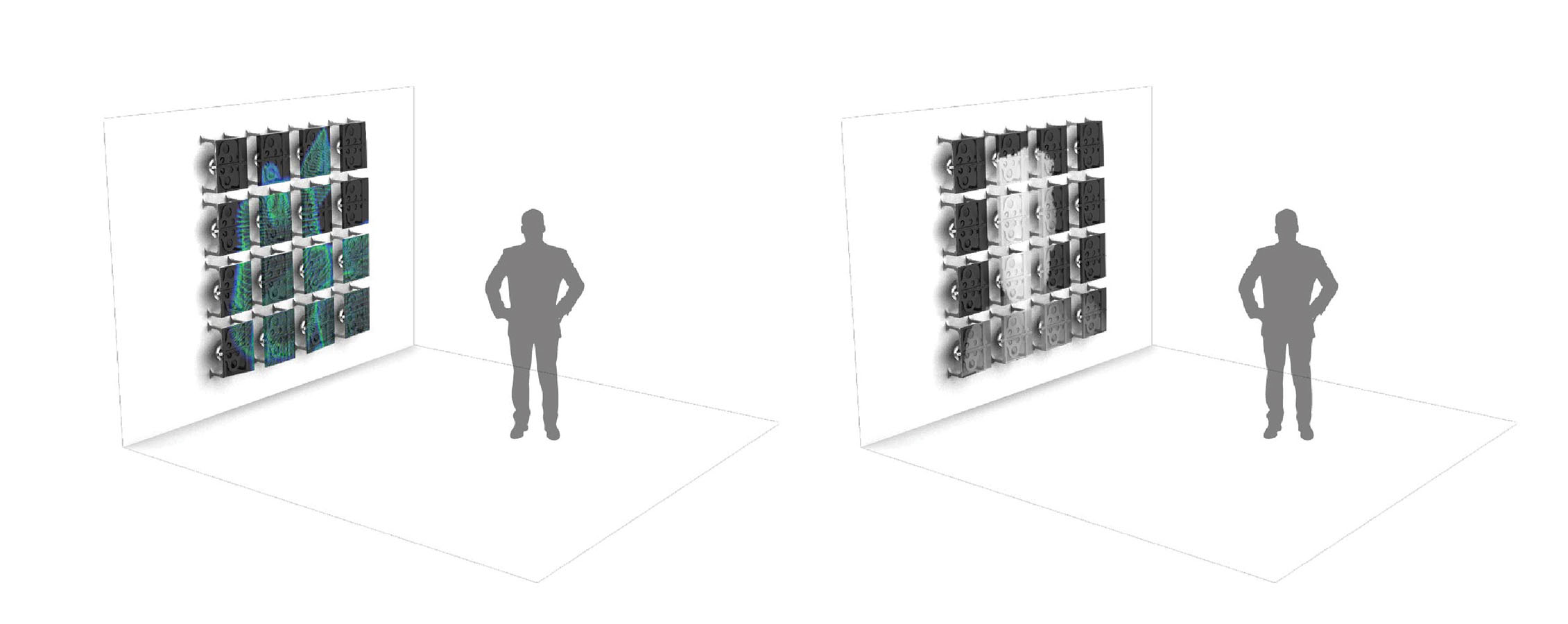
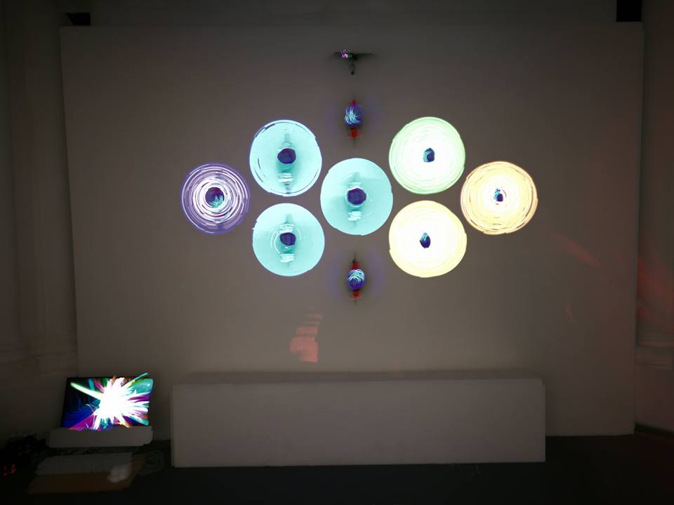
Overall I am super satisfied of what I’ve achieved in the end. The hardware operates as expected. The interaction experience works smoothly. The software that I’ve uploaded on the installation is a simple ripple that simulate the act of walking on the rainy day. This working perfectly fine but the possibility that this display could show much more complicate pattern still waiting to be explore.
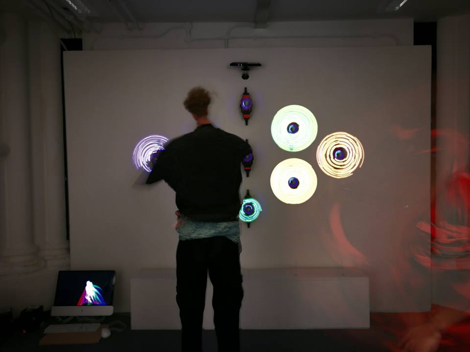
From three exhibition days, I witnessed a lot of people moving in front of my installation, interacting, and ended up enjoying and smiling. This give me a really warm feeling. The wall we used to know is not a blank lifeless compartmenting piece of architecture anymore, it had become ‘the thing’ that people can have fun with.
This whole project had enabled me to see that one can incorporate interactivity into any kinds of physical form or structure. Once transformed, that form or structure can offer whole new experiences and benefits to its users. This made me believe that if even a wall can be fun, then any objects could become even more interesting, resourceful, and enjoyable simply by installing creative, user-friendly, problem-solving, and interactive aspects into it.
Future development
As I told at the start that this project might not be the first intentional project that I want to achieve. The result had shown that possibilities are now endless. Therefore, I would like to explore more on the software part of this project, to discover what type of patterns are suitable for this circular floating screen and explore more on the interactivity between user and the graphics. As for this project, I only used frame differencing to detect movements. What I can visualize myself doing next is using the Kinect’s Depth Sensor to determine the speed of the motor. As the nature of this POV display give the transparency to its background, I would like to locate it a middle of the space where visitor could see what going on behind the screen instead of the white wall so the unit can create a double-sided detection of movements and synchronize with the system to present certain visuals and interactions accordingly.
Hopefully, I could finish this journey then I could start the original plan that I made 5 months ago, the vertically linear interactive unit.
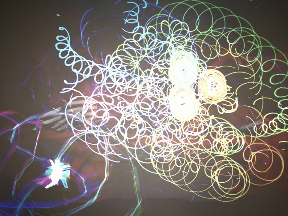
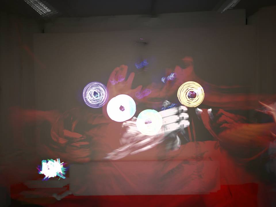
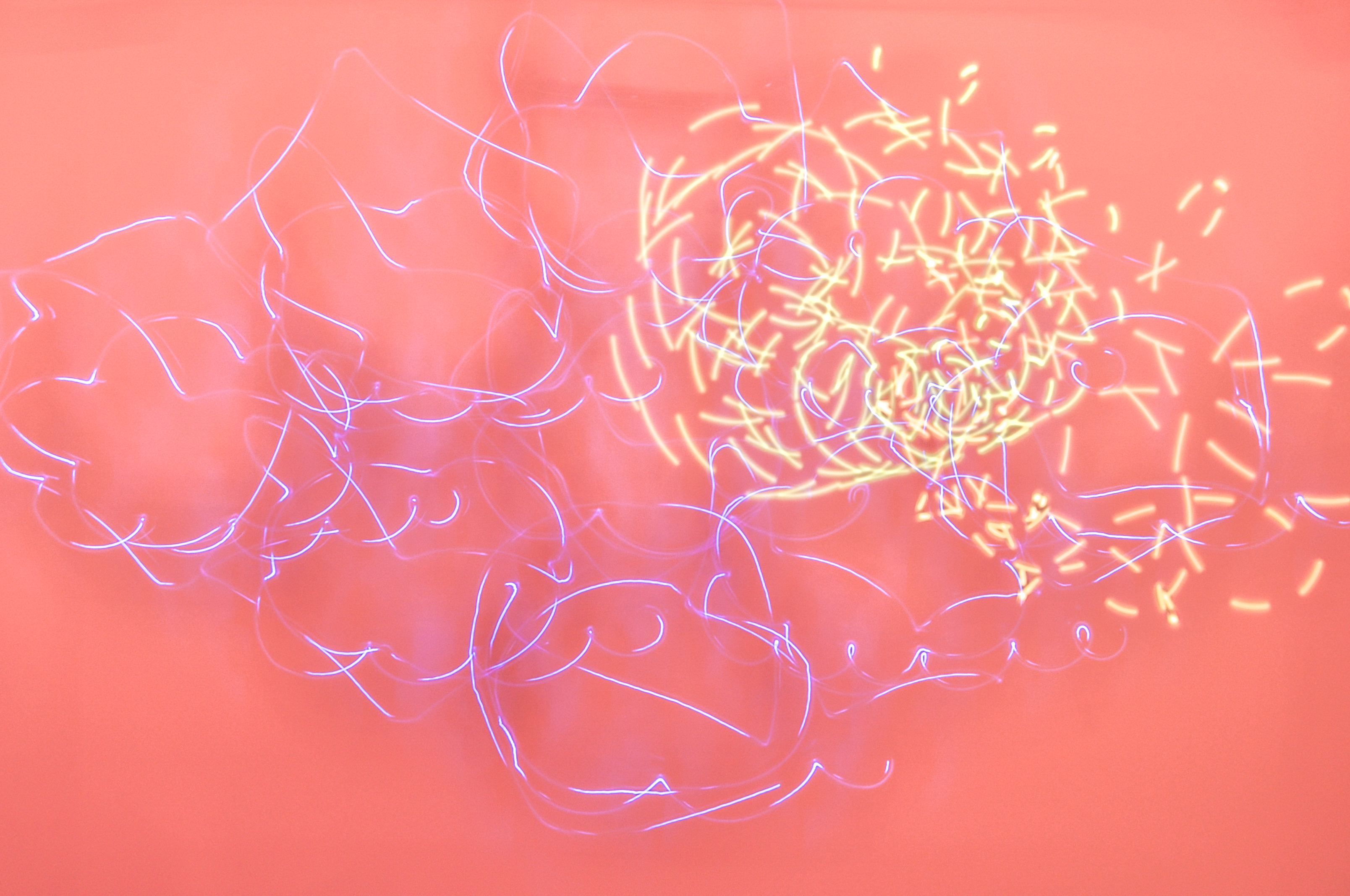
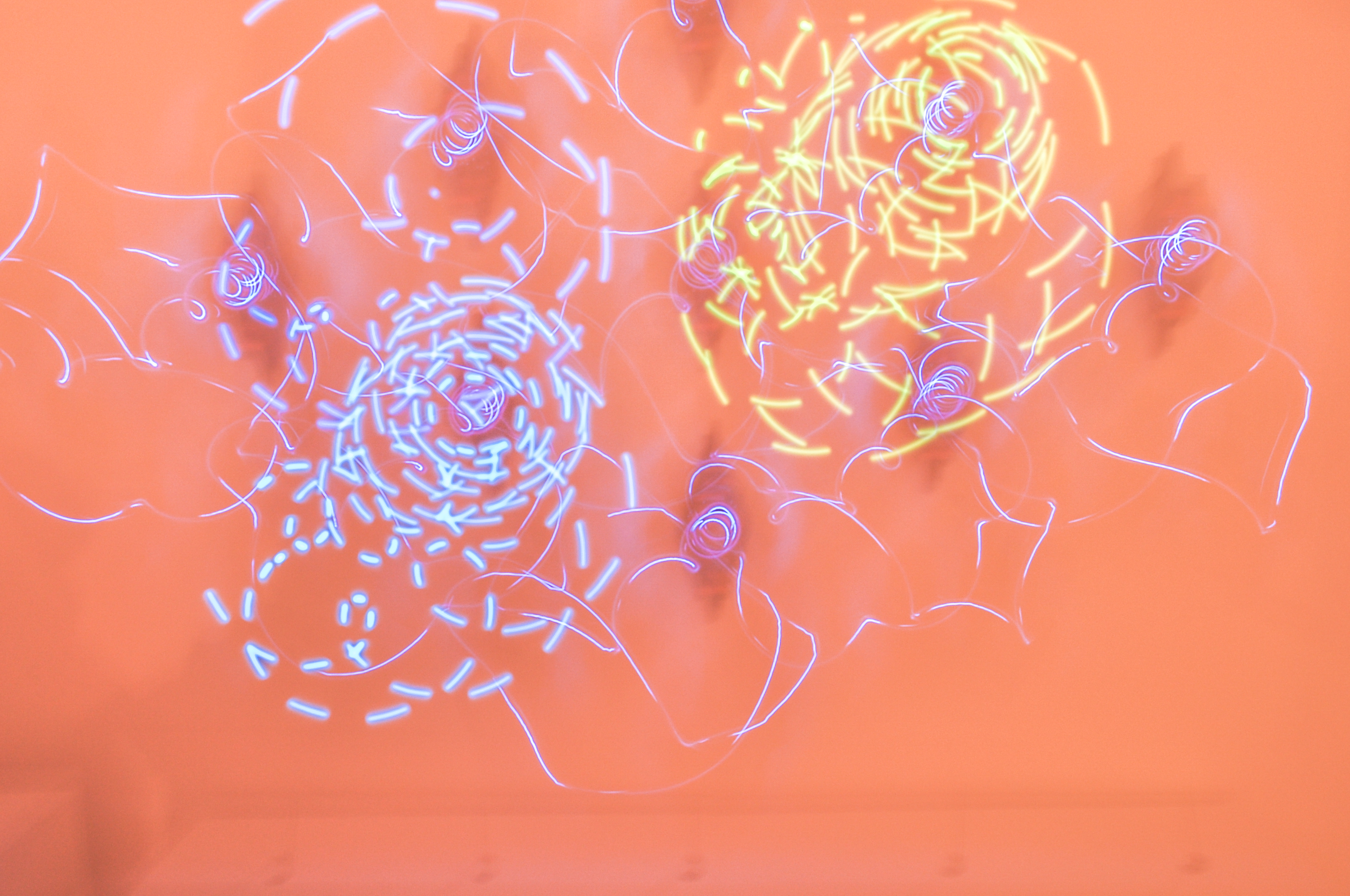
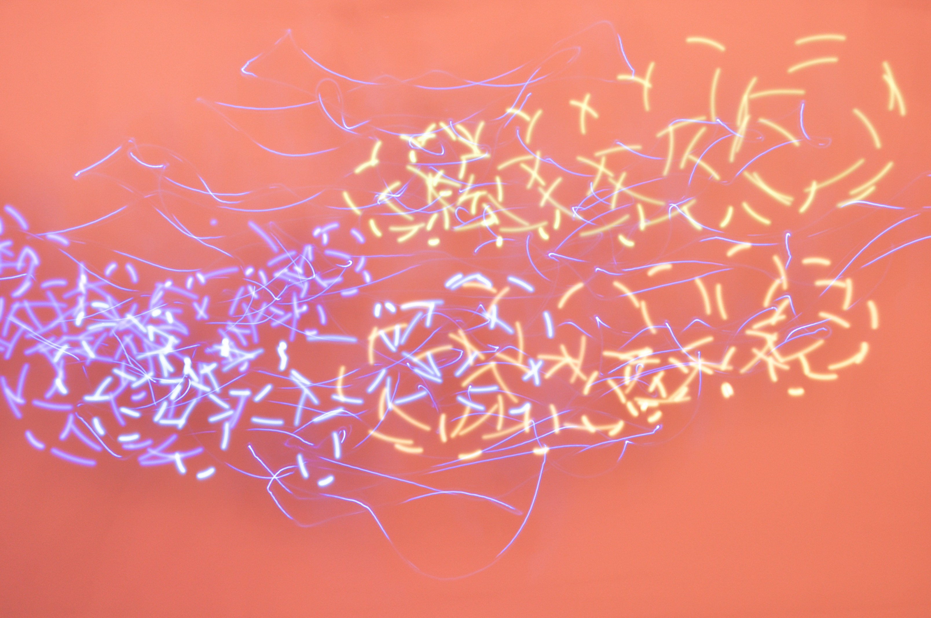
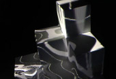
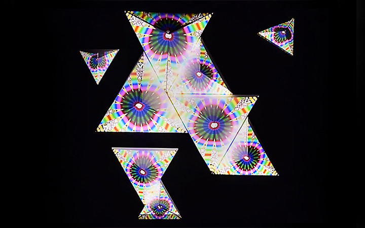
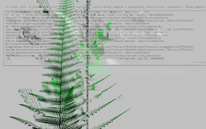
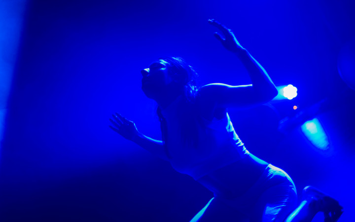
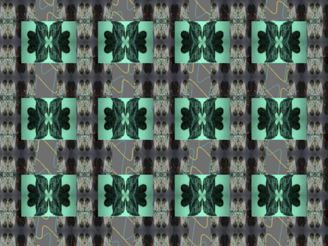
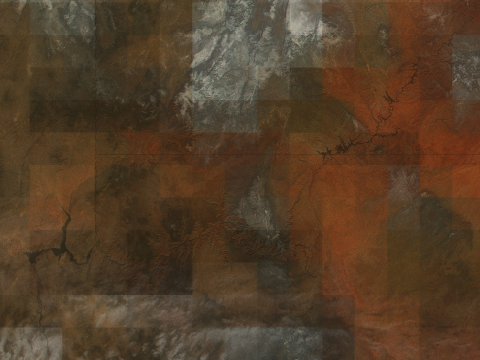
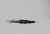
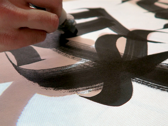
Artistic images
Images by Sand Padermprach & Noc Juengsophonvitavas
References
- http://www.instructables.com/id/PropHelix-3D-POV-Display/
- ofxkinect, ofxopencv
- https://www.youtube.com/watch?v=57carjNxI9A
Thank you
- Daniele Mancini for an inspiring talk about Persistence of Vision
- Konstantine & Pete to provided me a material and machine consultant
- Theo , Atau and Lior for giving me helpful advices along the way
- Sand Padermprach for food support and video editting consultant (can not thank you enough especially about food)
- Peaky Sakuldeelert for helping carry my life outside of this project and proof read my documentation
- Mimi Thanida & Mint Yossaya for travelling support after the exhibition
- Lastly I would like to thank you to everyone along this wonderful jorney