


Blue Mandrake
Guy Caradog Morgan, MFA 2017-2019
Term 1 final project documentation.
Materials: Arduino Uno, LEDs, piezoelectric speaker, photoresistor, wood, glue, blue polypropylene cord. |
Concept
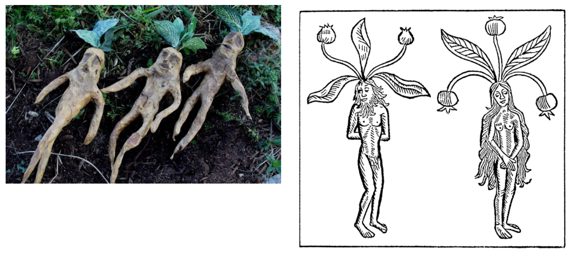
I've been interested in witches and folk medicine for many years, and thought it would be fun to make an interactive mandrake.
The mandrake is a root with arcane connotations – the legend is that it screams when you pull it out of the ground, and that anyone who hears the scream instantly dies. I wanted to make an organic-looking mandrake root that 'screamed' and lit up when you pulled it out of the ground.
This article gives a nice overview of the myth of the mandrake: https://www.wired.com/2014/06/fantastically-wrong-mandrake/
Idea development
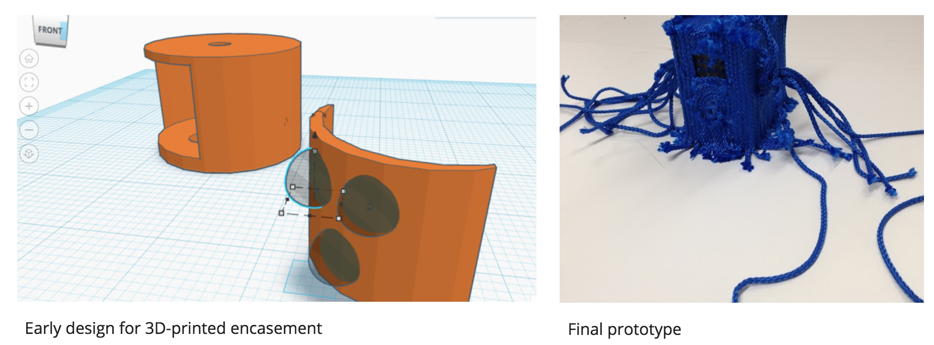
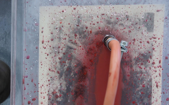
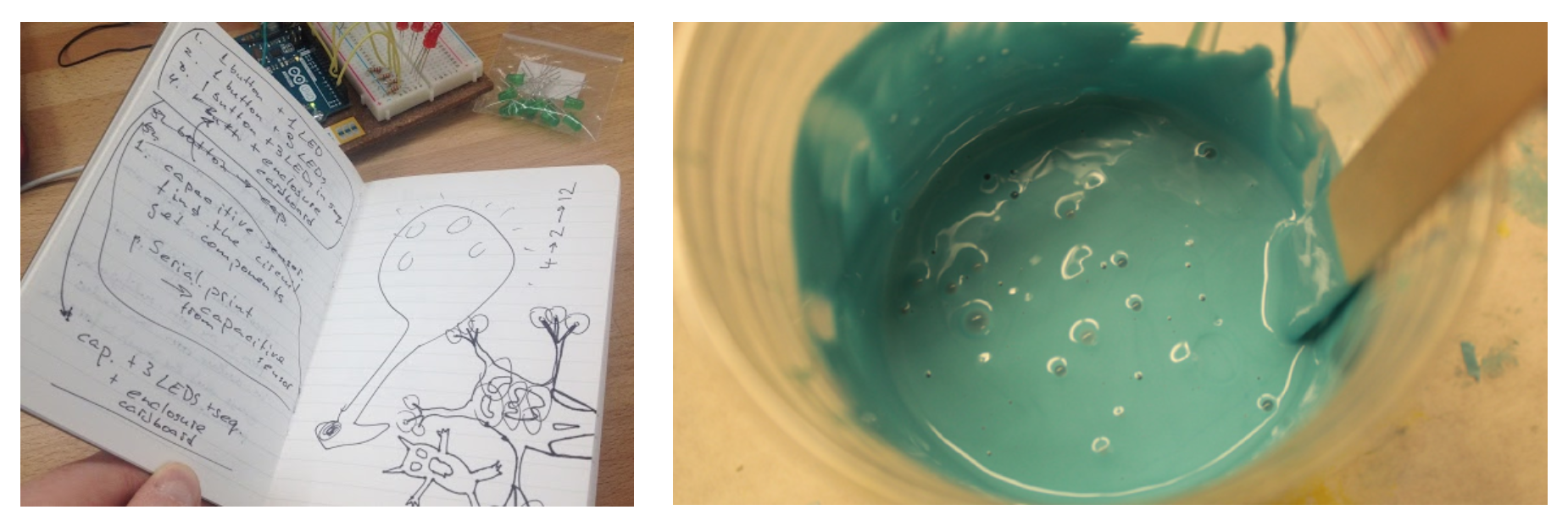
I had some silicon and blue dye left over from another project, so initially was interested in making something which looked and felt very organic, and that reacted to touch. However, the casing for this would have required 3D printing a box to place inside a more organic sculpture, plus the silicon casting process was likely to become too resource intensive for this project. It also left little room for error, and whilst I was developing the ideas for the interaction and circuit this seemed like too prescriptive an approach.
Quite late in development, I decided to switch to a simple wooden container – and to make this the basis for an organically-developed, root-like exterior – allowing more freedom to develop and trial different circuits.
The idea of capacitive sensing got thrown out when I decided to go with a harder container – and in any case, I started thinking about what it was that 'made' the mandrake scream. It's provoked by exposure to light, one supposes - so I decided to use a photoresistor.
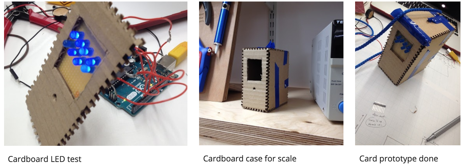
Playing around with configurations of LEDs led to me deciding on a matrix – I looked into multiplexing but decided on a smaller number of LEDs that could be directly controlled on a 1:1 basis from the Arduino Uno's pins.
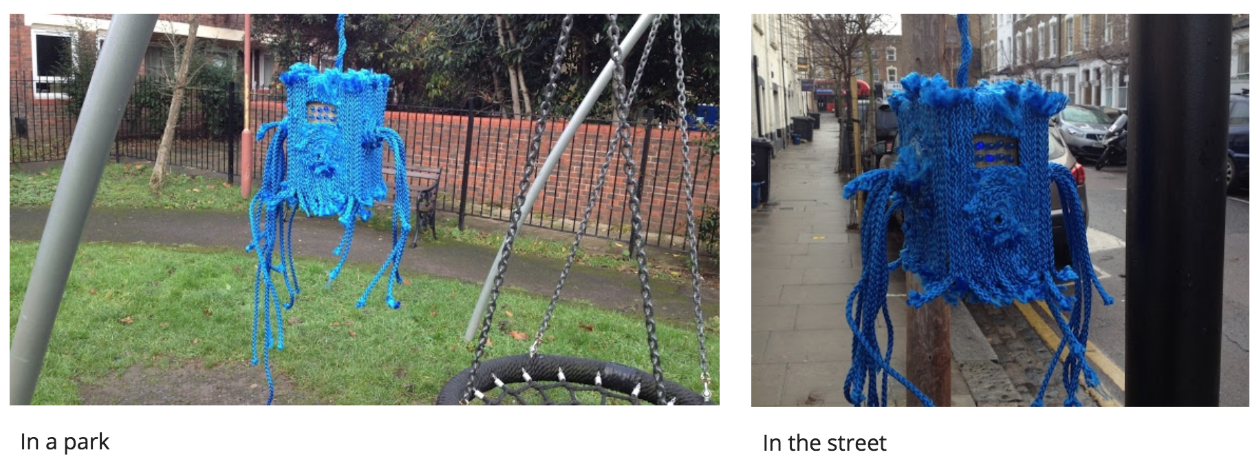
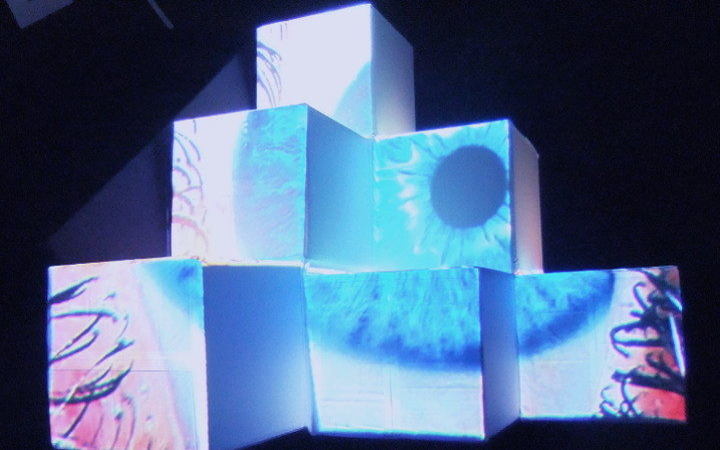
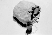
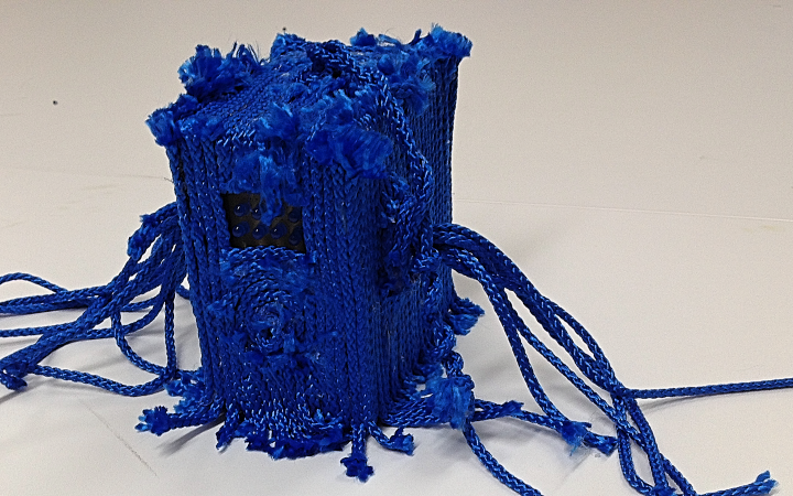
The colour blue stuck from the earliest idea, and I got some glossy blue cord from a hardware store which I thought would have a pleasing organic feel to it – it would allow me to create knots and roots and to make patterns which reference organic material whilst also conferring a cute, craftsy presence to my little mandrake.
For the scream, I decided to go with a simple piezo buzzer. I sourced a few from an electronics store to try out. I'm aware of wave shields as used here: https://www.youtube.com/watch?v=tbR1wwDLnRg but decided to go with a piezo because I was still thinking about making an unpleasant 'screaming' sound and I wanted it to feel like an embodied circuit ghost / bionic mandrake thing.
Technical details
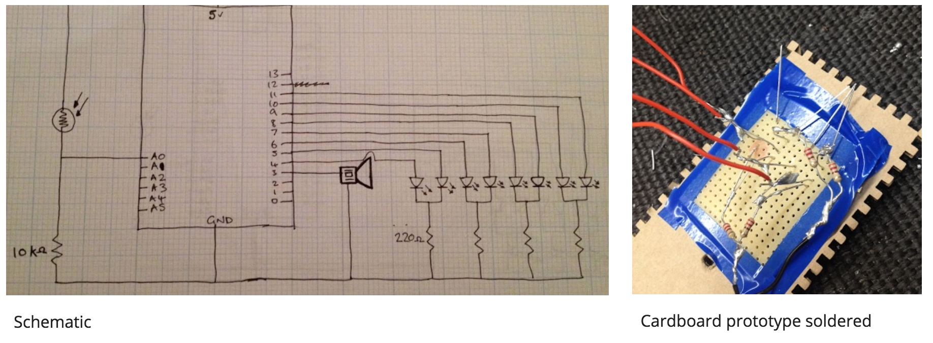
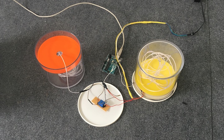
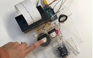
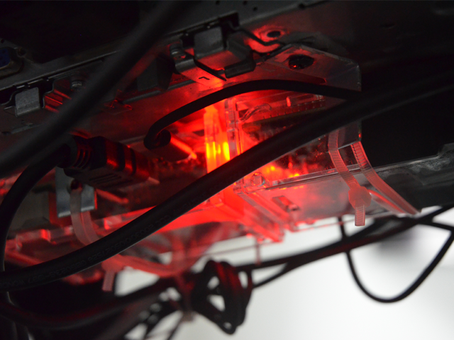
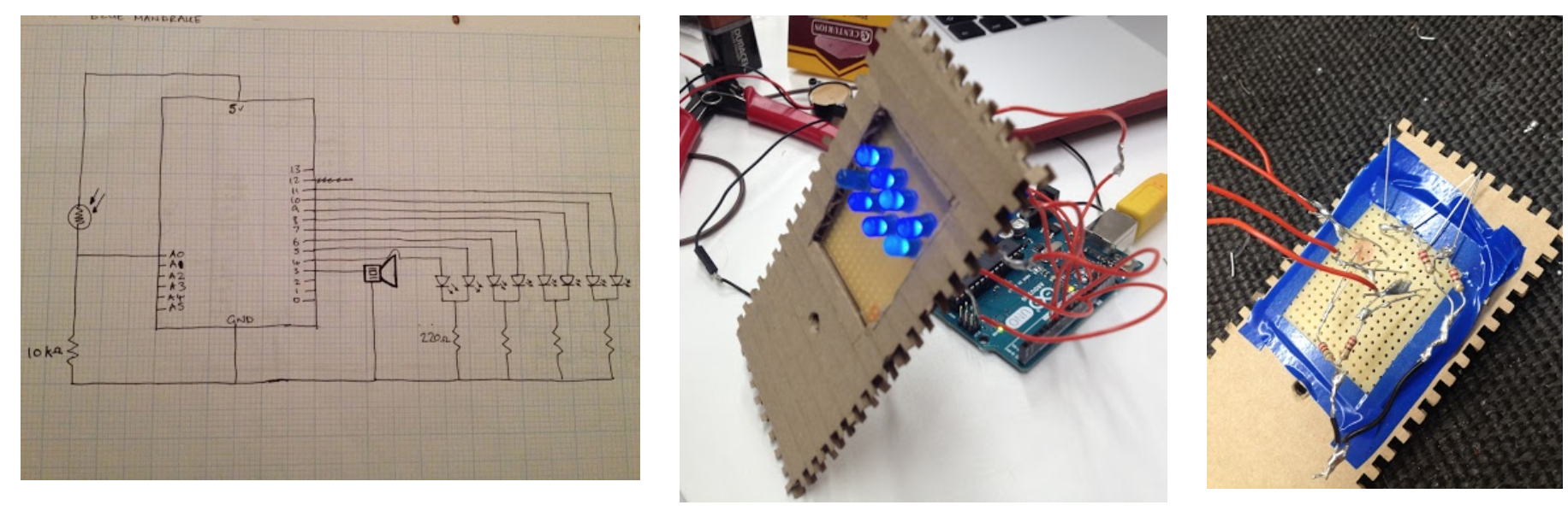
The technical set up for this is very simple – a photoresistor is connected to the A0 sensor pin and ground through a 10 kilo-Ohm resistor. This sets a baseline, and then acts as a switch when the input goes above a threshold (trial and error set this at 2x baseline).
If the photoresistor's input crosses the threshold, a sequence of LEDs and a piezo tune (using the Arduino tone() library) plays through. At the end of each cycle, if the input is still high, the sequence replays. If not, it stops. (Tone library: https://www.arduino.cc/reference/en/language/functions/advanced-io/tone/)
The LEDs are blue (to match the exterior) and so two LEDs are put through a shared 220 Ohm resistor on the way to GND. The 5mm blue LEDs I used have a ~3.4V drop across the resistor, so one 220 Ohm resistor should be enough to reduce the current from 2 LEDs in parallel to ~20mA.
The code has been split up into functions for ease of organisation – but the program uses more memory than it should. Future improvements would include more abstracted thinking about the LED pins in order to sequence LEDs using for loops, and the use of binary, lower-level messaging to change multiple pins at once as suggested here.
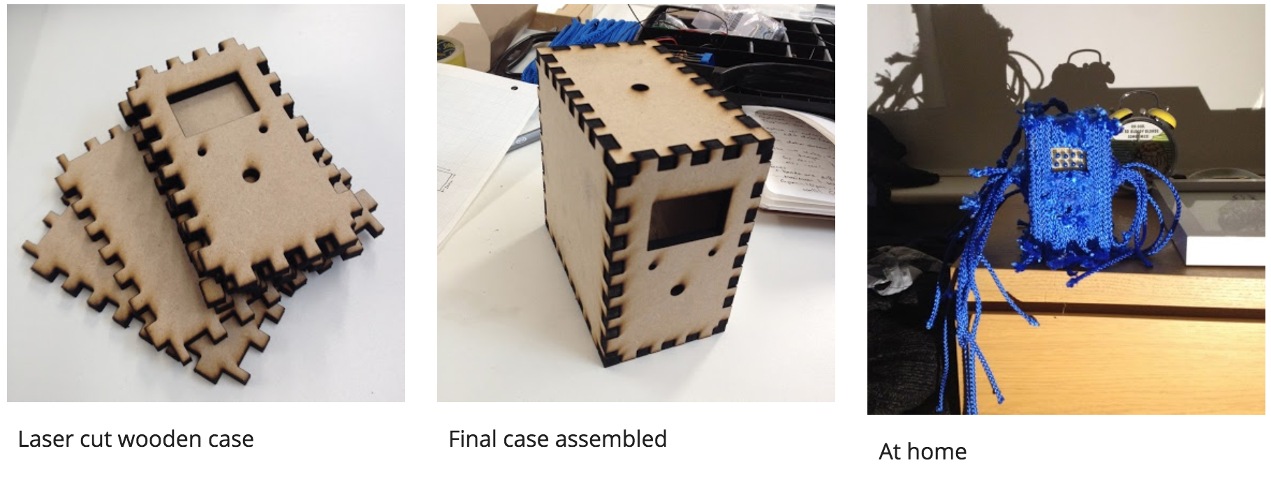
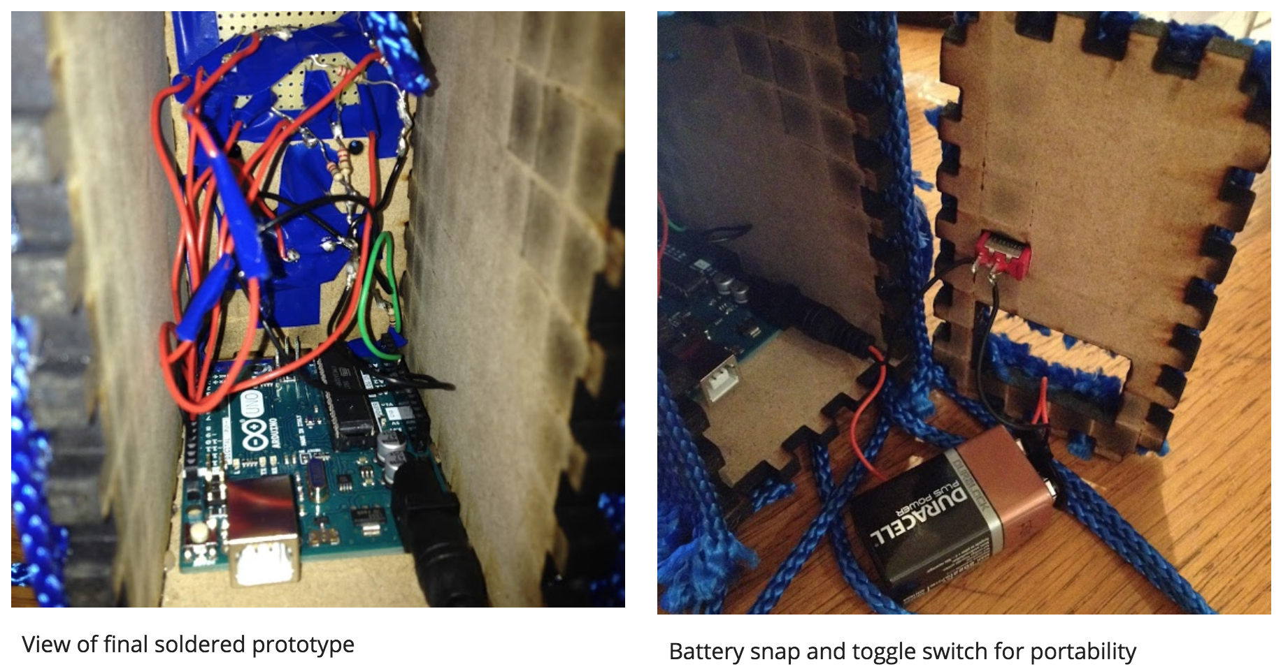
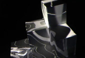
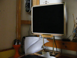
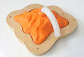
In terms of the fabrication - I did 3D print a very small housing for a prototype but rejected the 3D printing approach as too inflexible. A cardboard laser-cut housing was used to test dimensions - this highlighted some crucial details, such as needing a hole in the back for a toggle switch and how to position the 'eyes' and 'mouth'. A final SVG schematic was made using http://www.makercase.com/, edited in Adobe Illustrator, and then laser cut from a 9.5mm thick sheet of wood. Then the outer 'organic' layer was hot-glued on.
The one thing that was carried over from the earliest design was the hole for a 'stalk' in the top and for the photoresistor in the bottom. The final wooden case was scaled up about 10% and had some dimensions changed - but I knew I wanted it to be portable, so it had to be a tight fit.