


Moving Paint
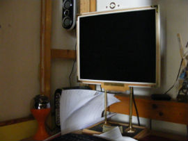
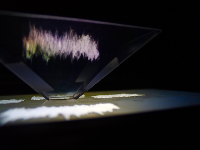
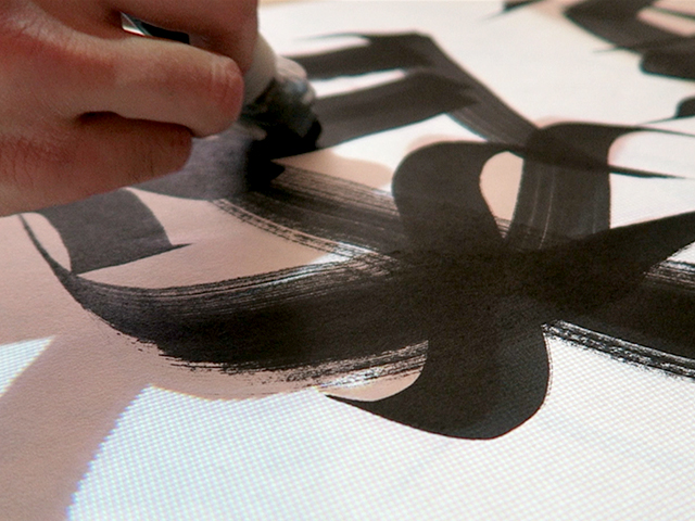
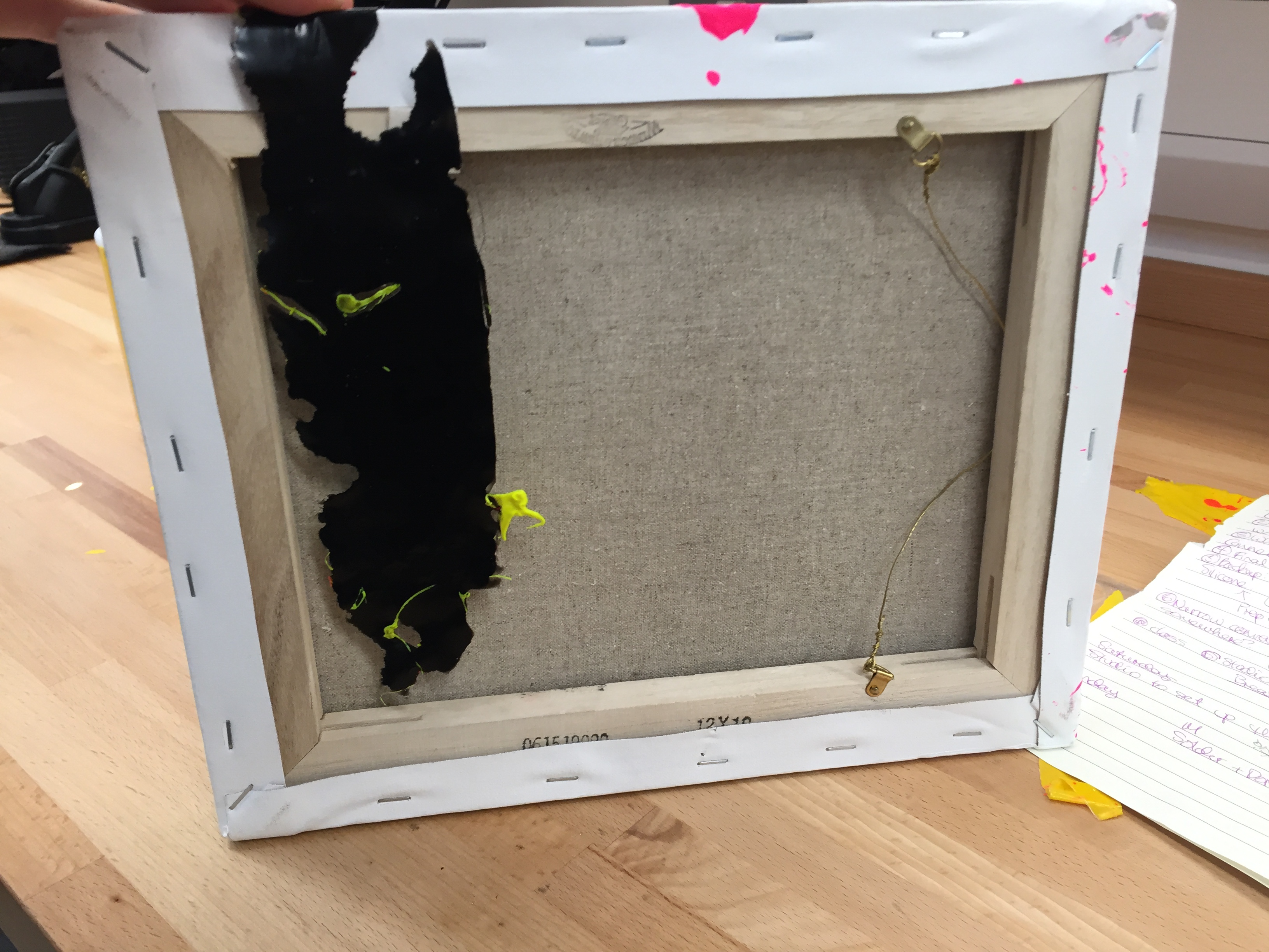
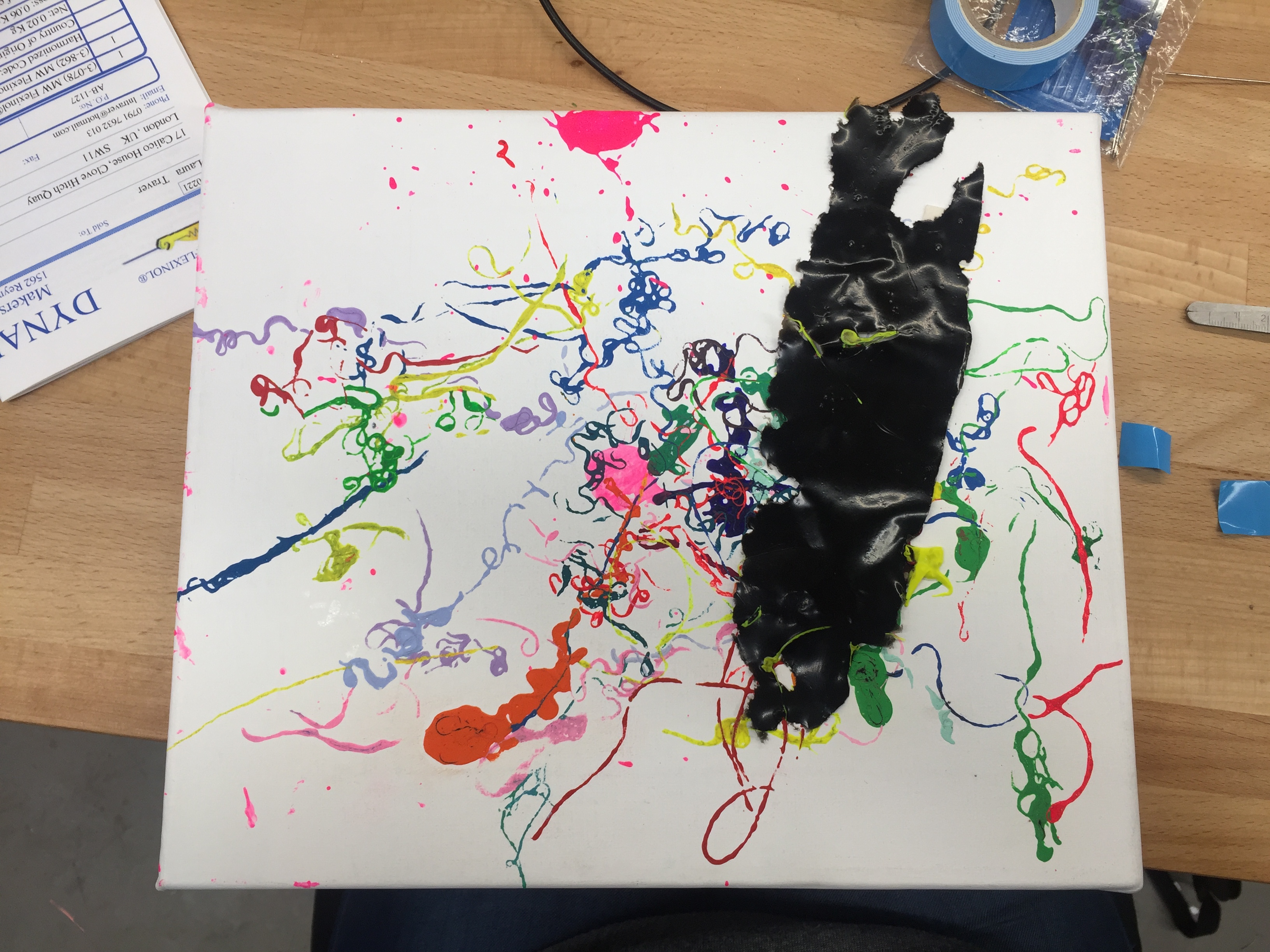
This project is a continuation of my work over the last two years exploring the materiality of paint and methods to detach it from support whilst maintaining its form. I started this work because I am interested in the physical act of drawing and painting and the remnants that each mark on a canvas represents of a physical person and unique movements. Detaching paint plays with this by decontextualising marks from fixed positions on the canvas or other support. For this project, I have used ultrasonic proximity sensors to activate transistor switches connected to muscle wires fixed to canvas so that when an object (the viewer) is within a certain distance of the painting, the marks become animated.
Produced by: Laura Traver
The initial process
I decided to use muscle wire because of its unreal and also lifelike behaviour and so I began exploring its technical characteristics. The wire ranges in size from 0.001 inches to 0.02 inches and current requirements increase rapidly based on diameter from 20mA to 4000mA. It was necessary to balance current requirements with the pull force of the wire as well as heat produced if I was going to attach anything to it. The larger the diameter of the wire the greater the pull, but the longer the resting period required and the greater the heat output. In addition, an Arduino can handle 40mA per pin and 200mA overall, this is likely why there is very little information on the use of muscle wire with Arduino. I determined that 0.005 would be a good diameter to start with as it has a pull force of 230 grams and required around 250mA of current with a resistance of 1.8 Ohms/inch with no real resting period to take into account.
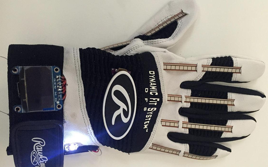
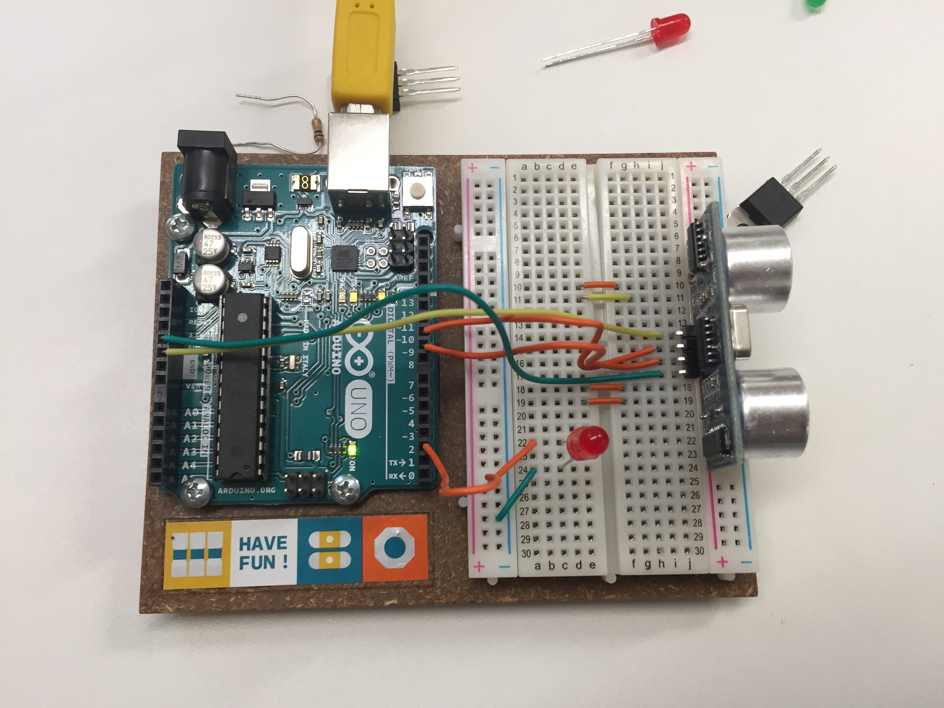
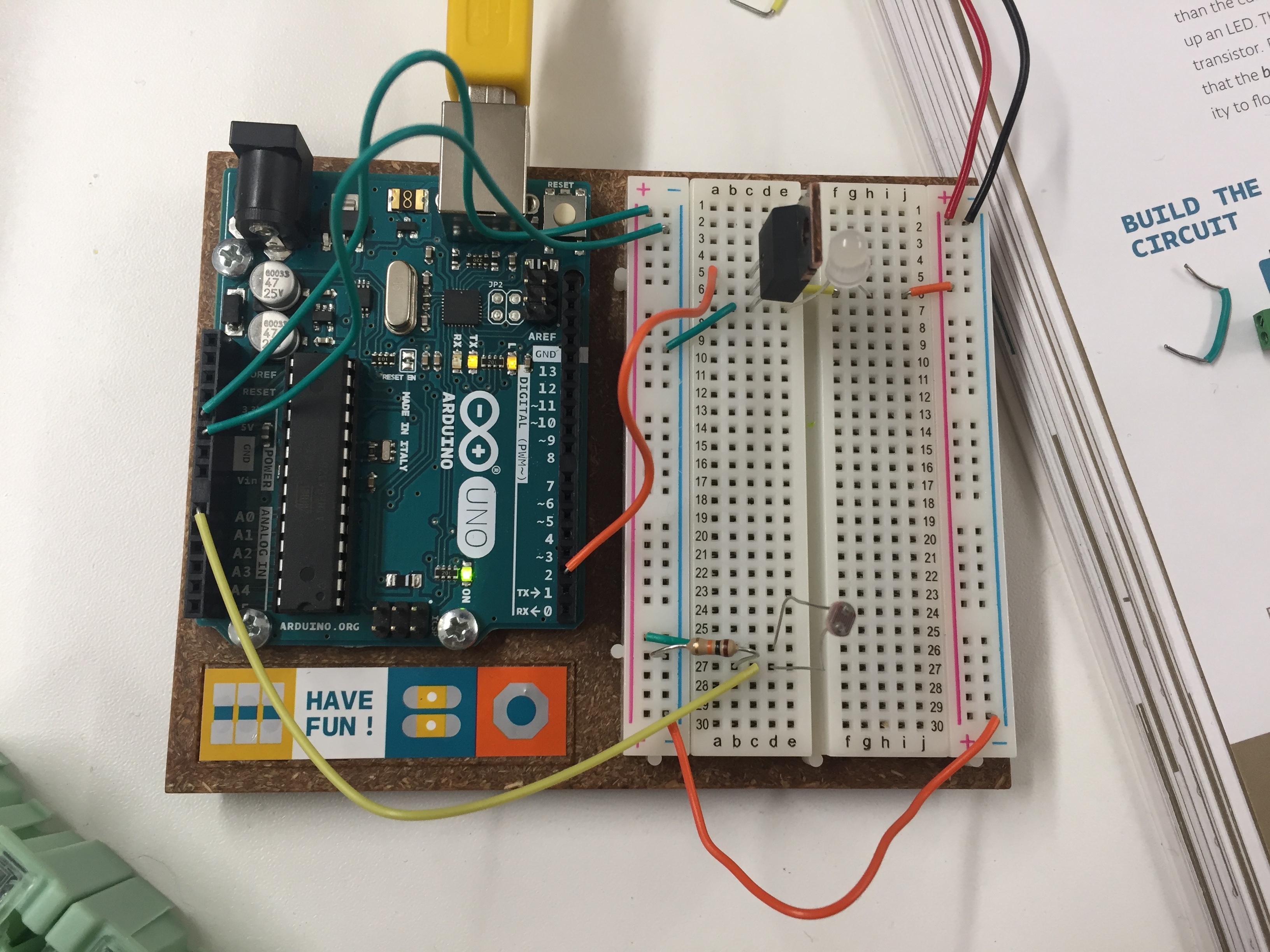
I began the development process by testing basic code using if statements with basic breadboard circuits using a photoresistor as an input and an LED as an output (see video). However, I wanted something that was capable of being used in a larger space such as a gallery space and so replaced the photoresistor with an ultrasonic HC-SR04 proximity sensor which sends out and receives ultrasonic soundwaves to determine distance and is effective up to 400cm. I initially tried this out with just one LED as an output (see video).
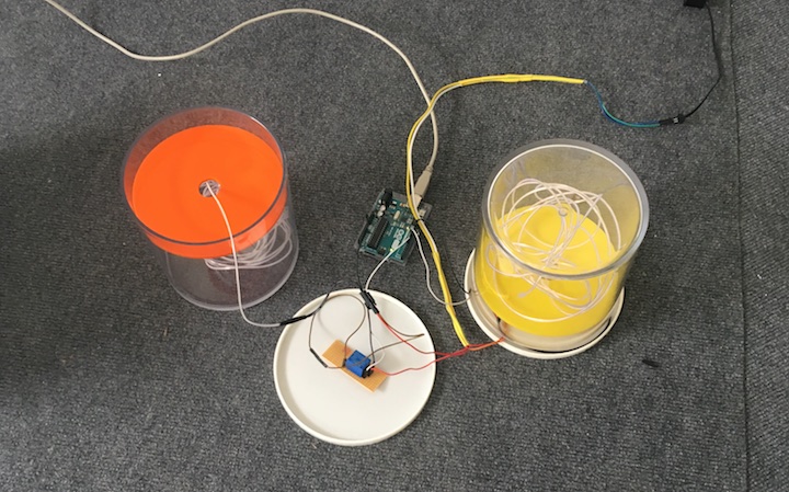
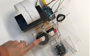
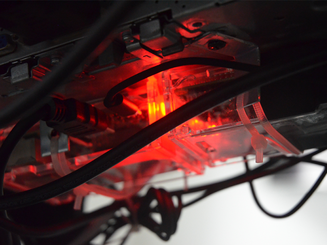
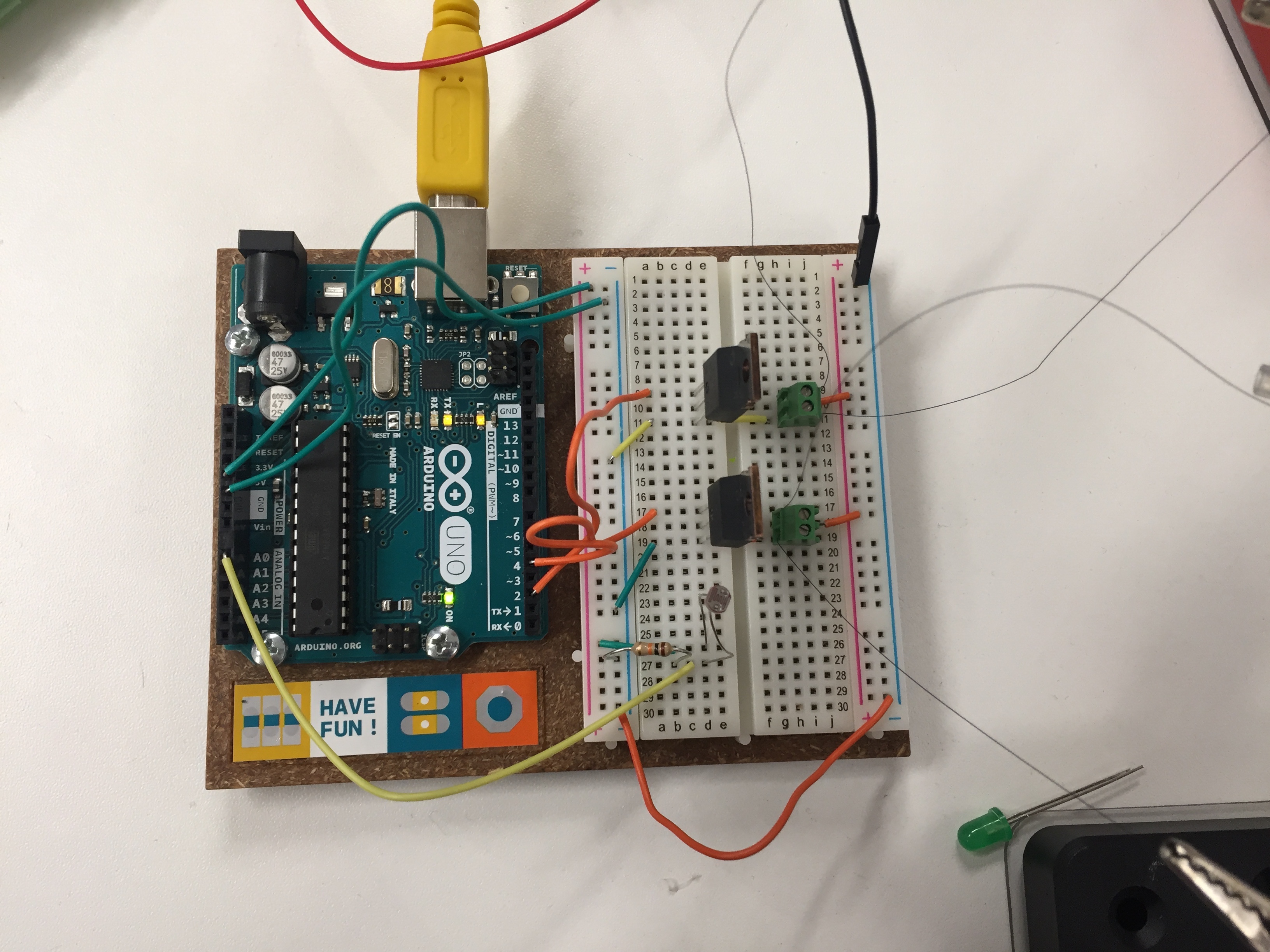
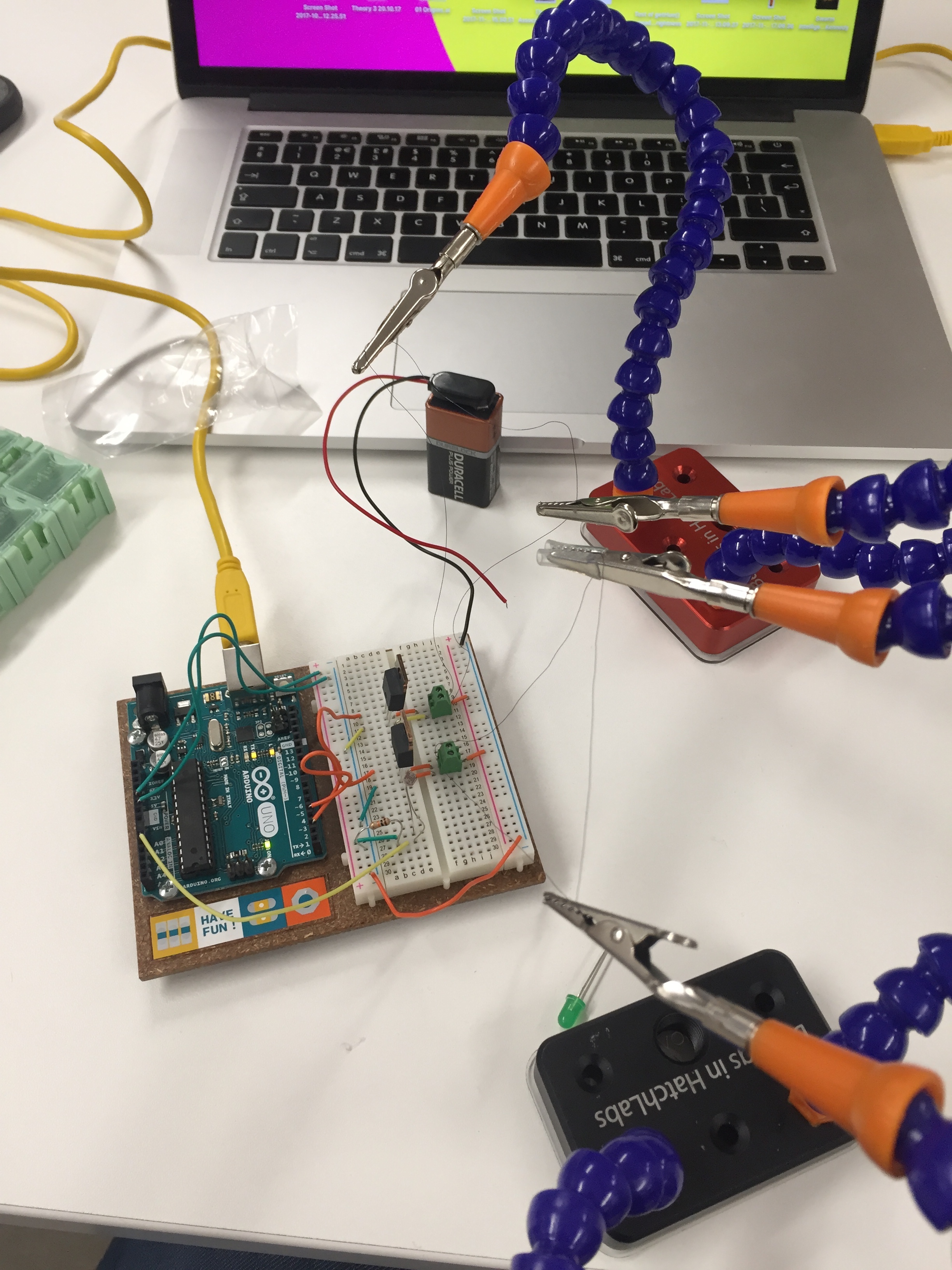
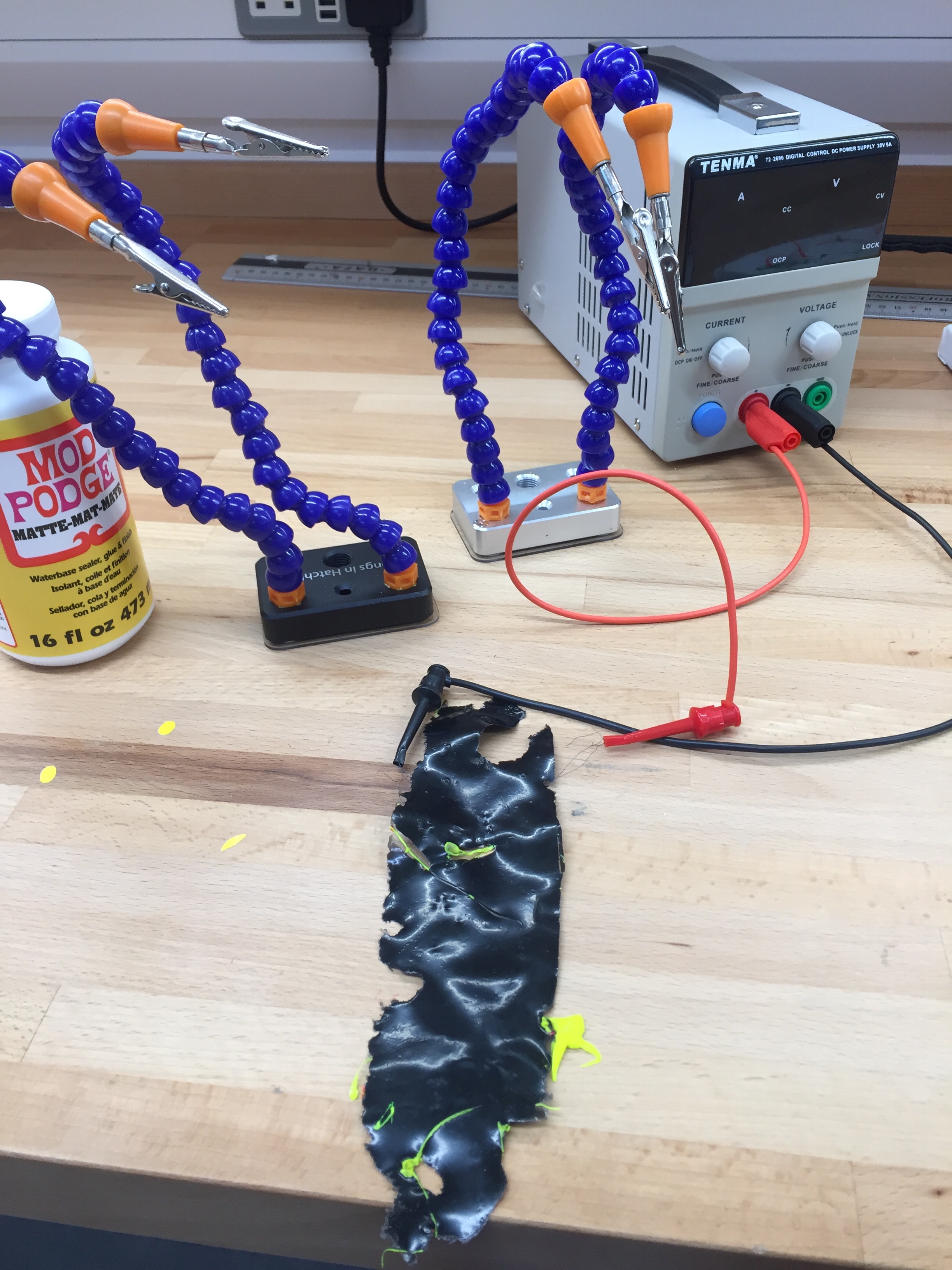
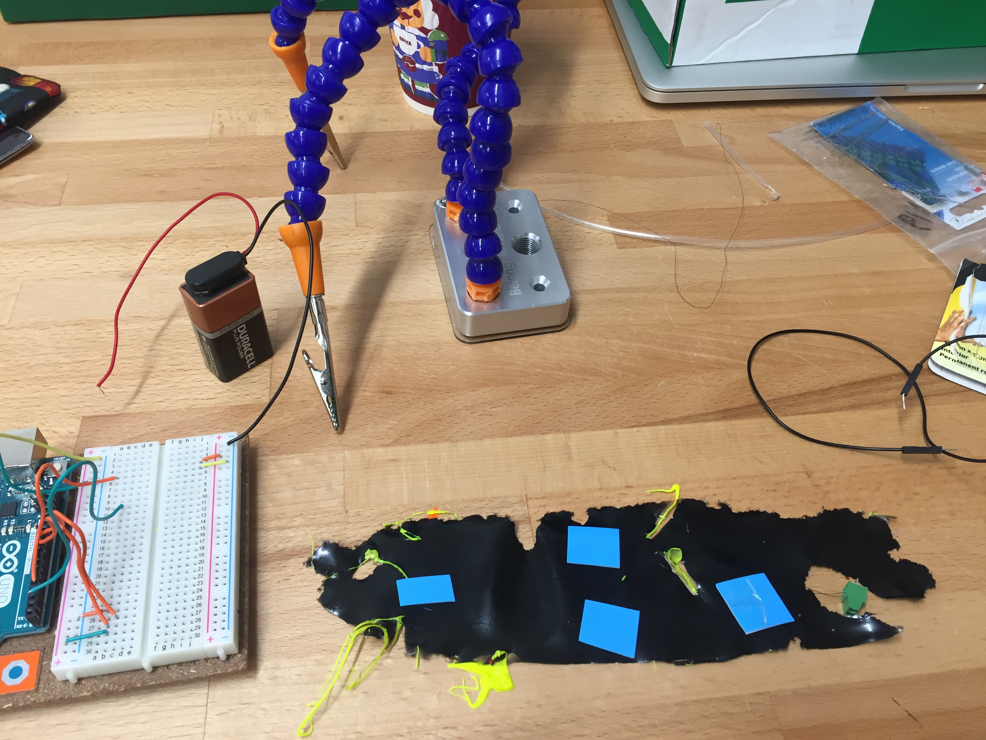
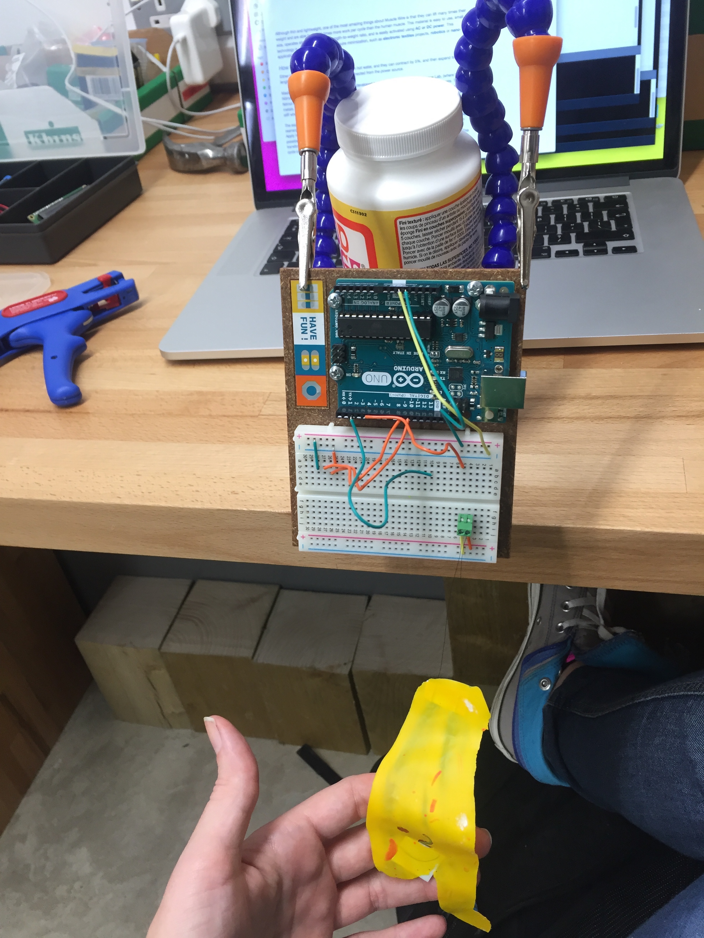
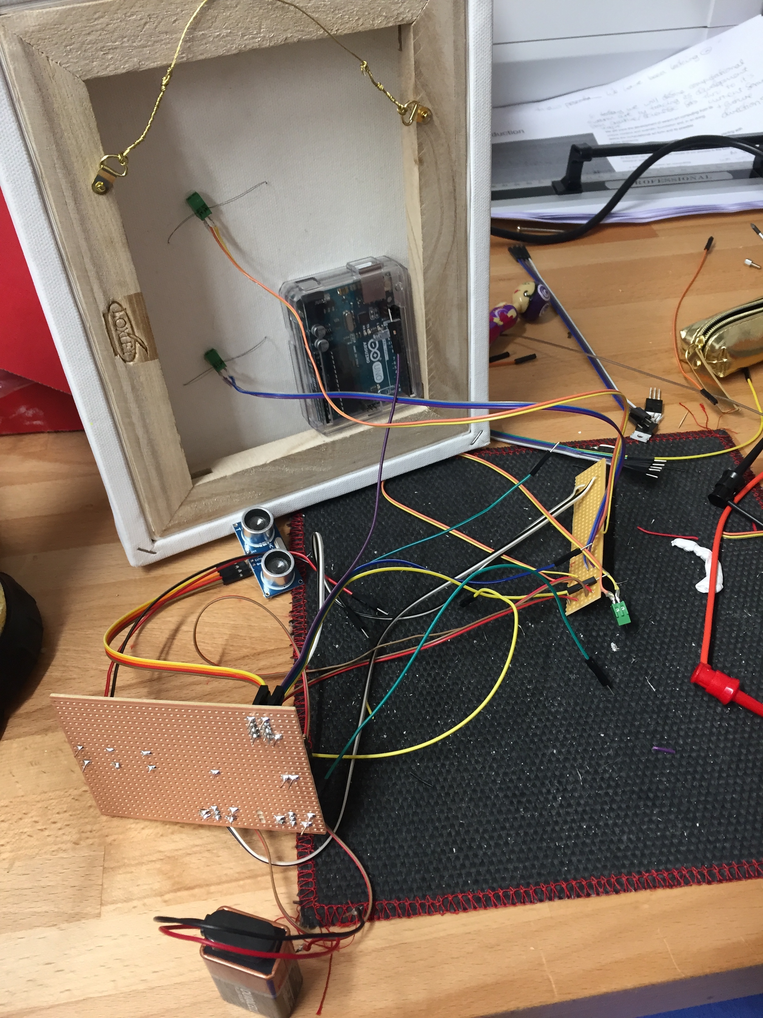
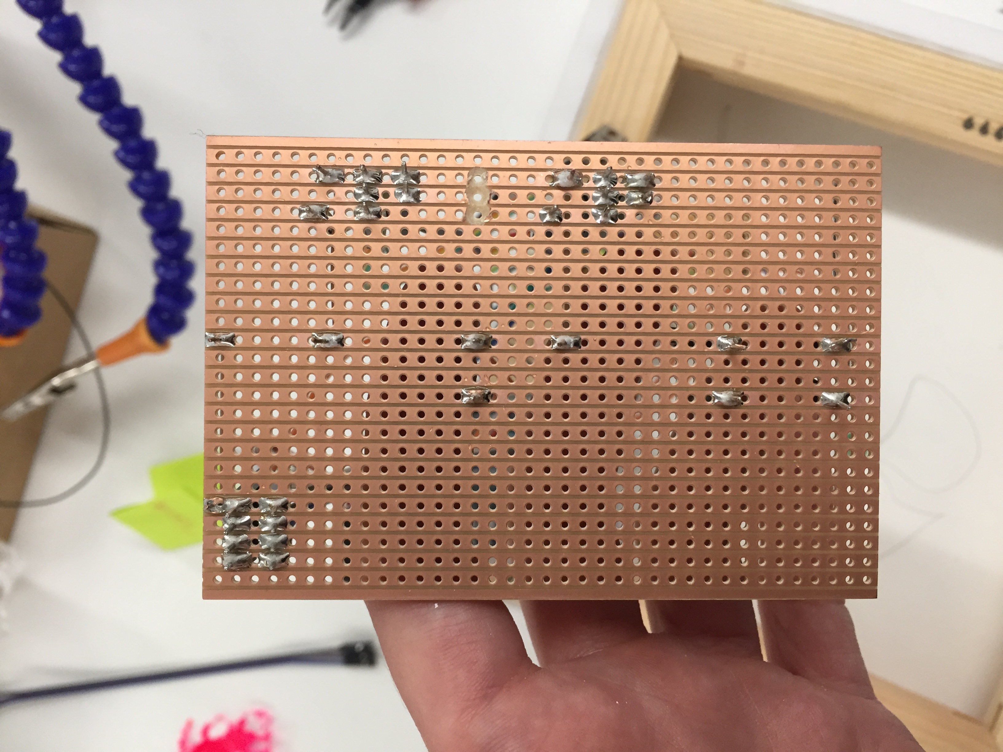
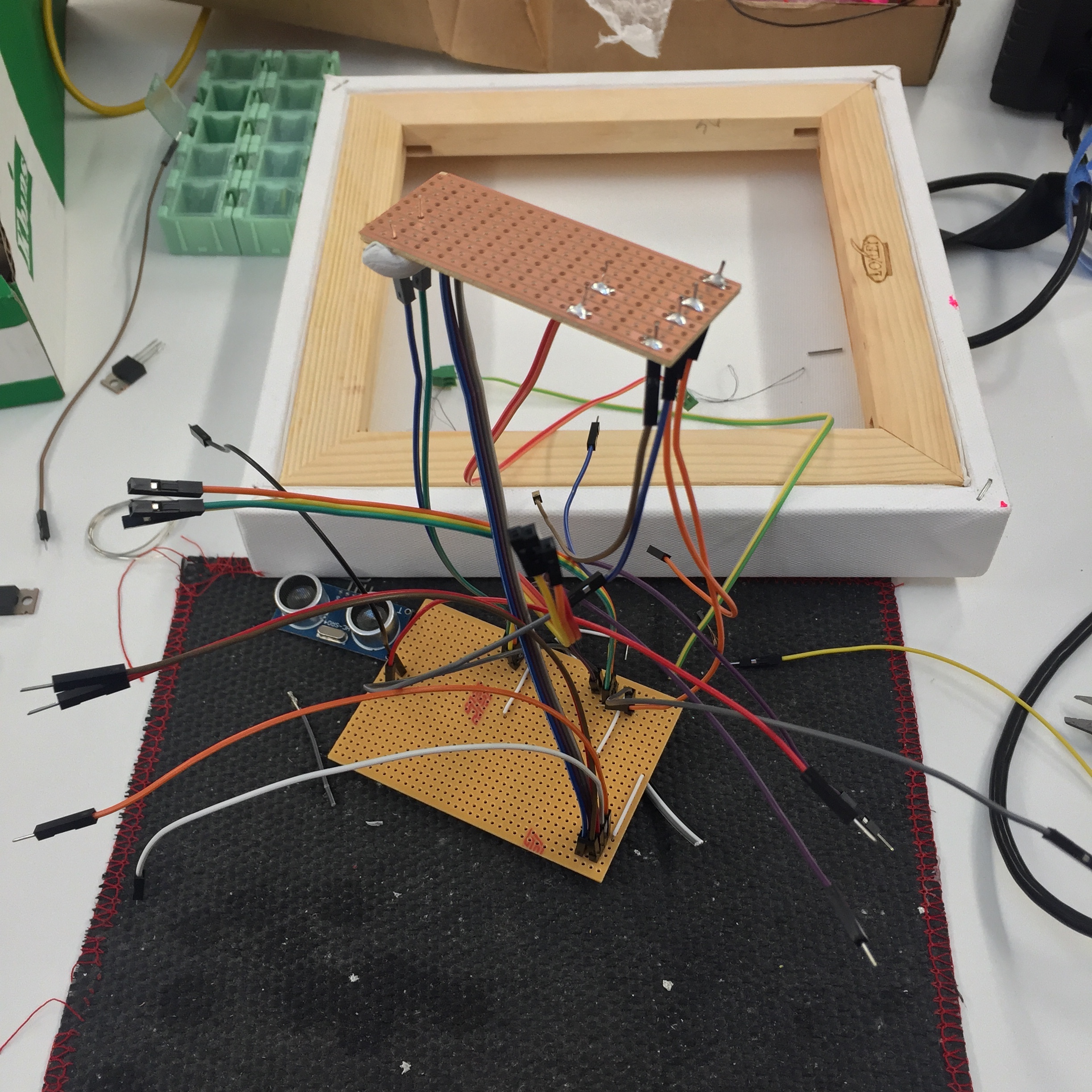
Separately, I also explored the behaviour of the wire by directly connecting it to a power supply. Through this, I learned that the wire has a narrow current range and that it is unique to each individual muscle wire - if it receives too much it can smoke and burn. Therefore, current sources would have to be calculated exactly for the number and length of muscle wires or I would need to use an automatically adjusting bench power supply. To start with, I introduced one muscle wire to my prototype breadboard circuit and a 9 volt battery along with a MOSFET transistor acting as a switch whilst also protecting the Arduino (see video). I then moved on to two muscle wires each connected to a separate transistor switch which were, in turn, connected to separate pins (image) and brought this together with the sensor. My prototype breadboard circuit was complete and I moved on to exploring the behaviour of the wire with paint and weight.
Refining
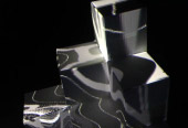
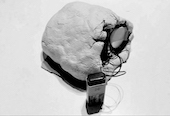
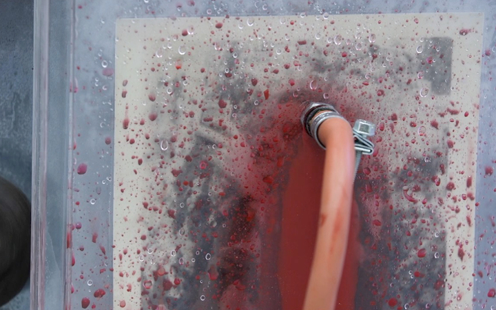
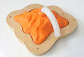
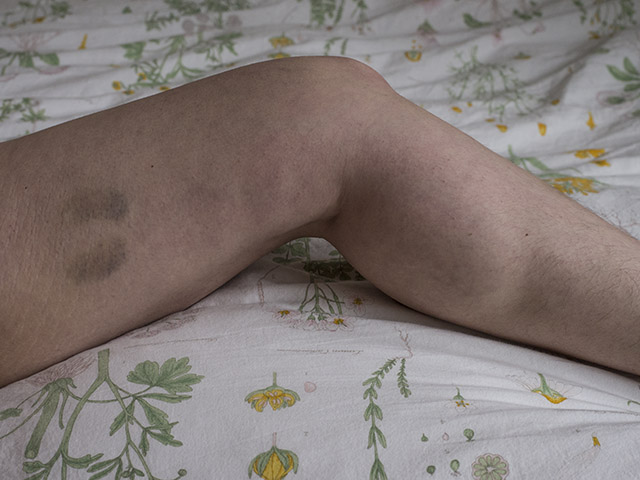
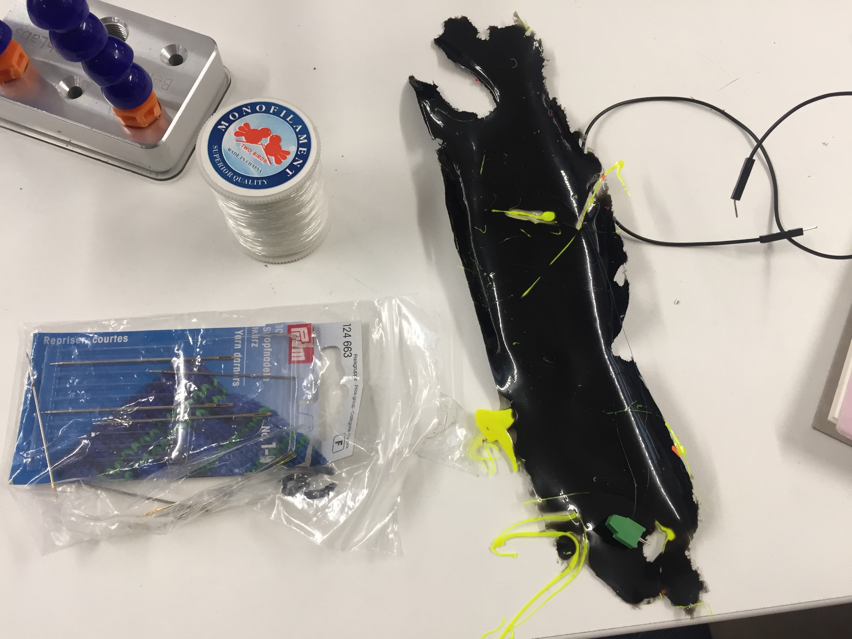
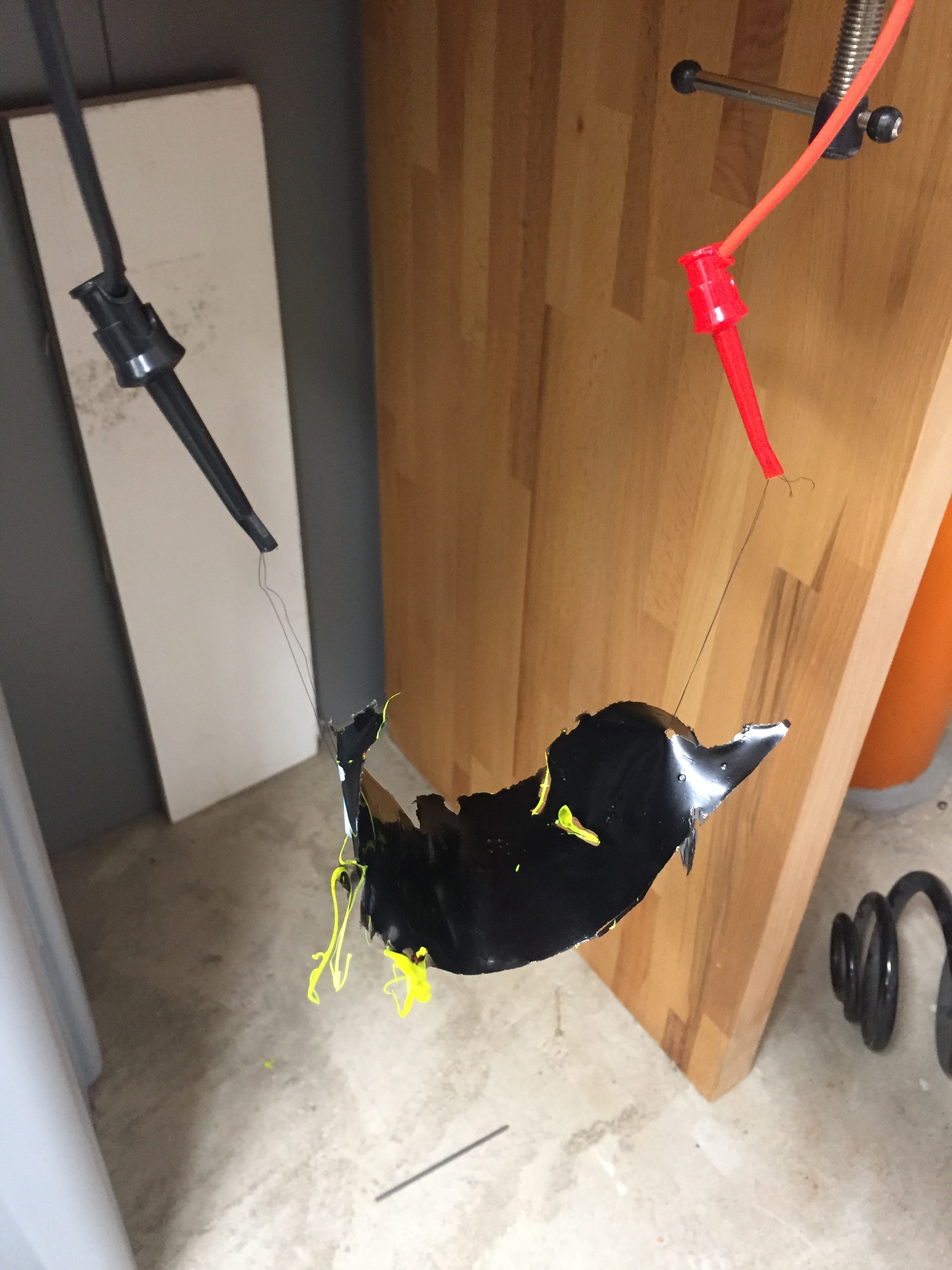
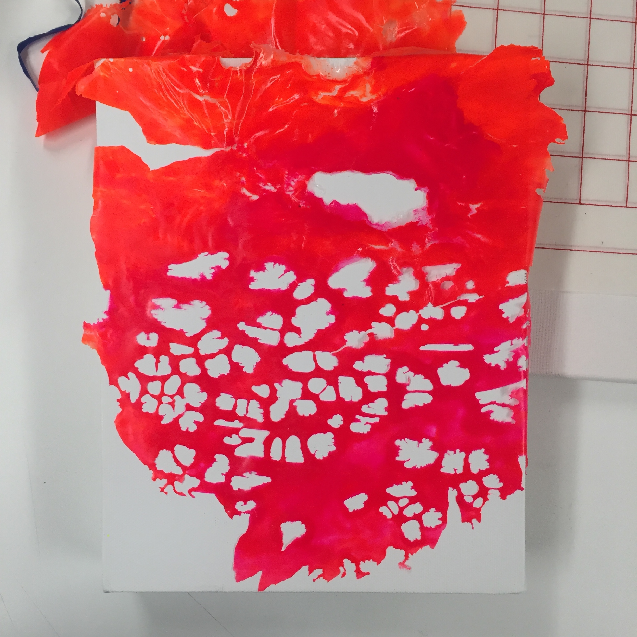
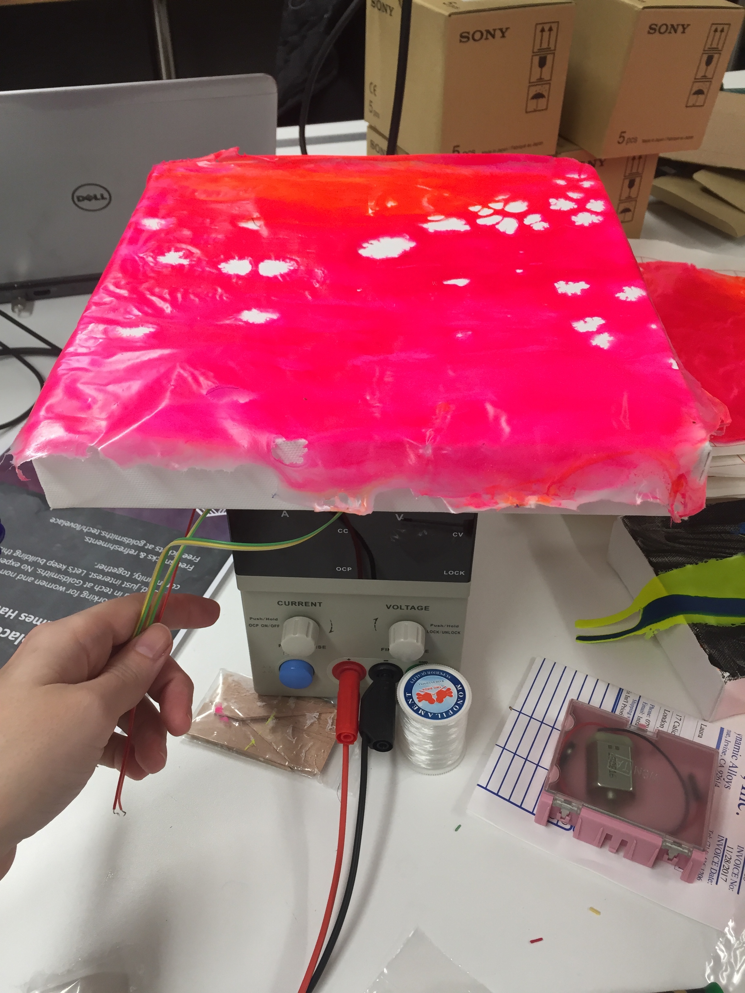
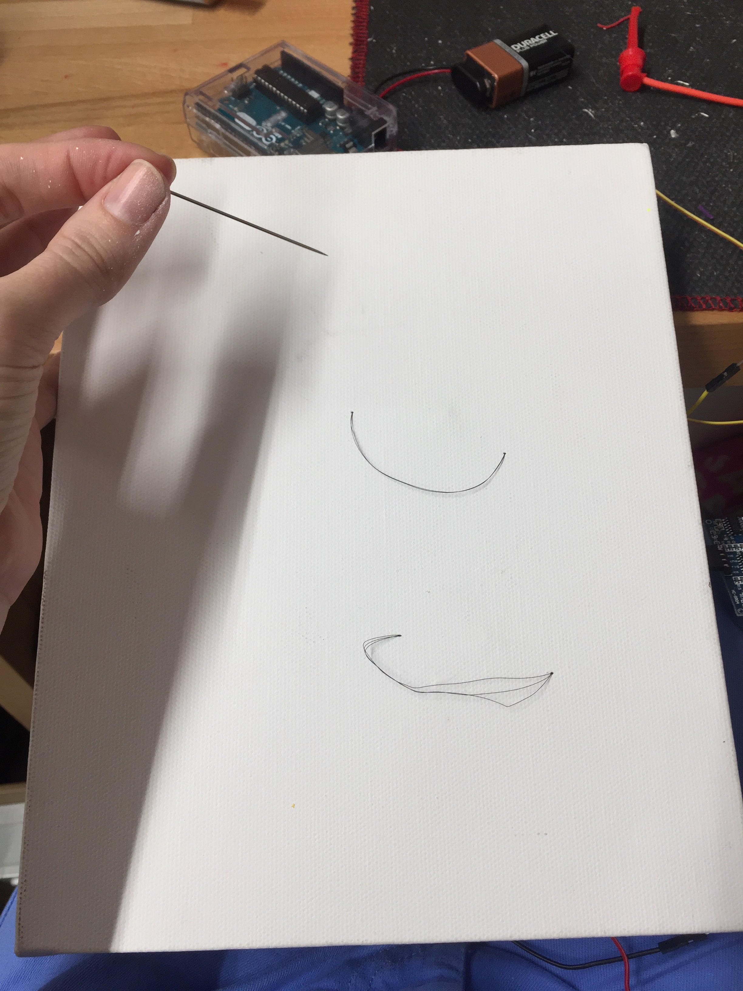
I prepared various sizes of paint to ensure I could explore different weights and characteristics of material (pictured). I then began experimenting with different methods to attach the muscle wire to the paint - sewing the wire to the paint, threading the wire through tubes glued to the paint, and taping the wire down to the paint. Ultimately, through this process of experimentation, cutting the wires in half (6 inches) and combining wires together in twos and threes to move freely provided the best lifting power. This increased the current requirements to around 1500mA with a low voltage of around 3 volts and an automatic bench power supply source was decided upon to power the project.
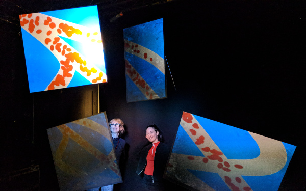
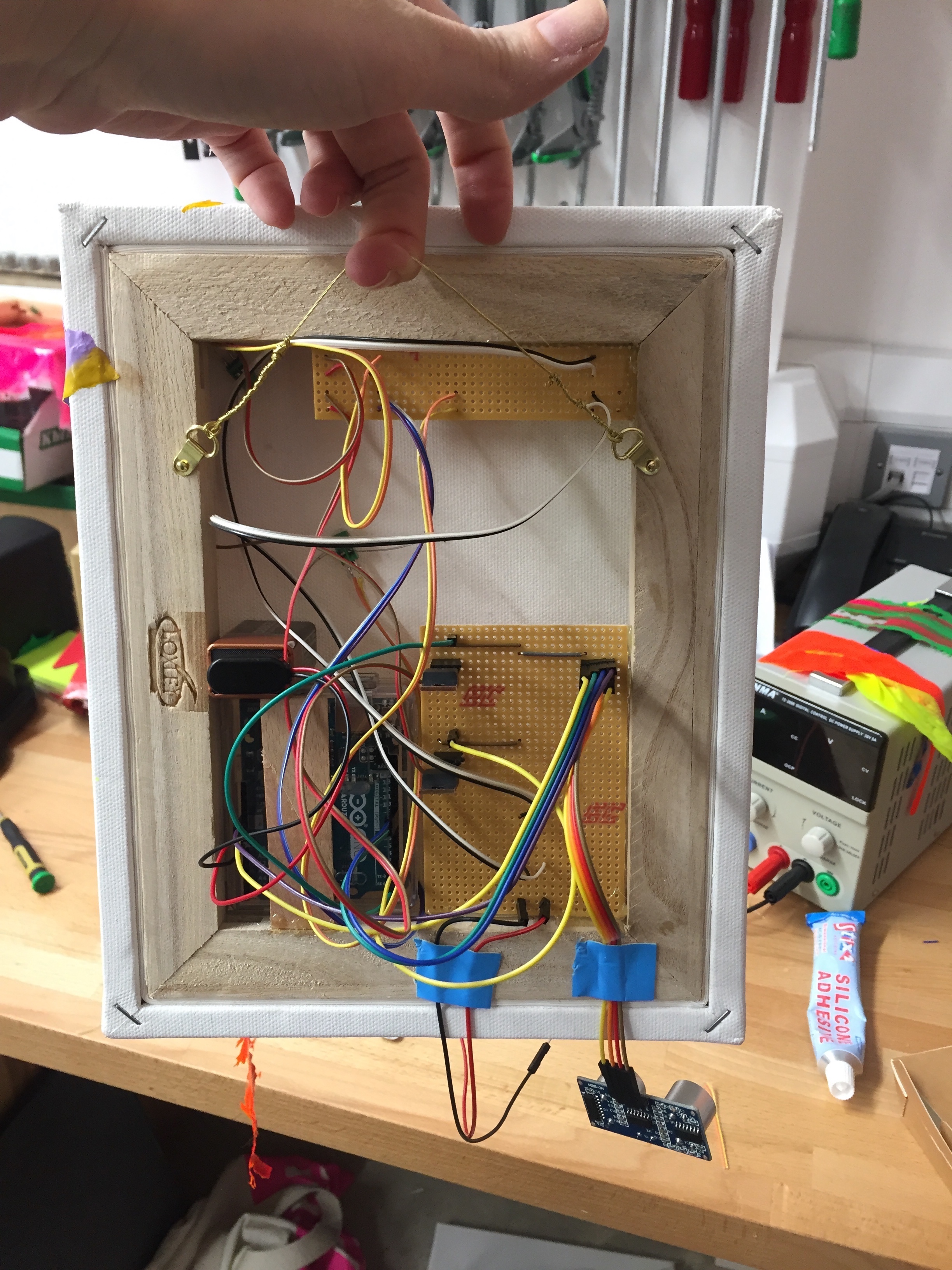
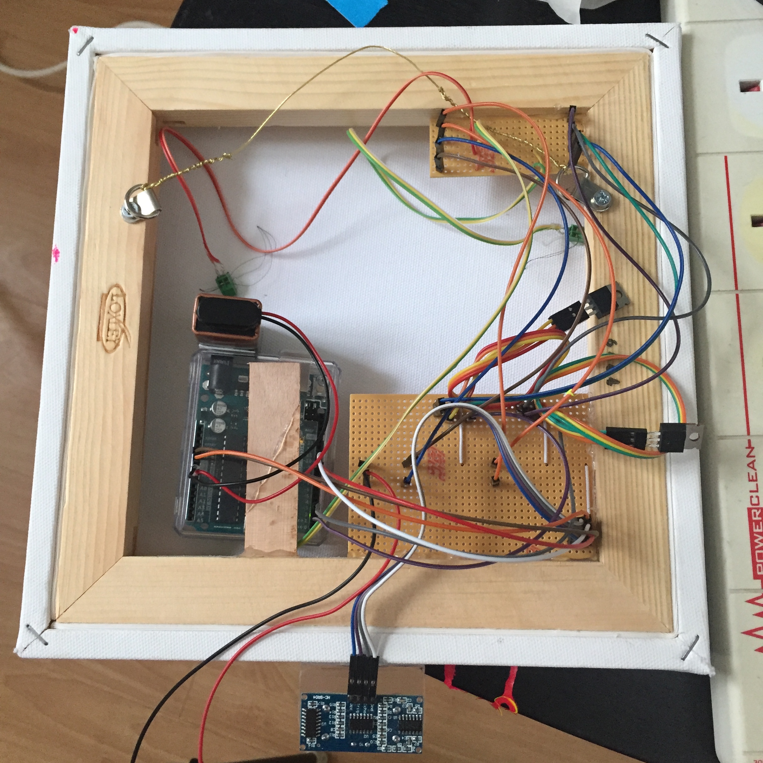
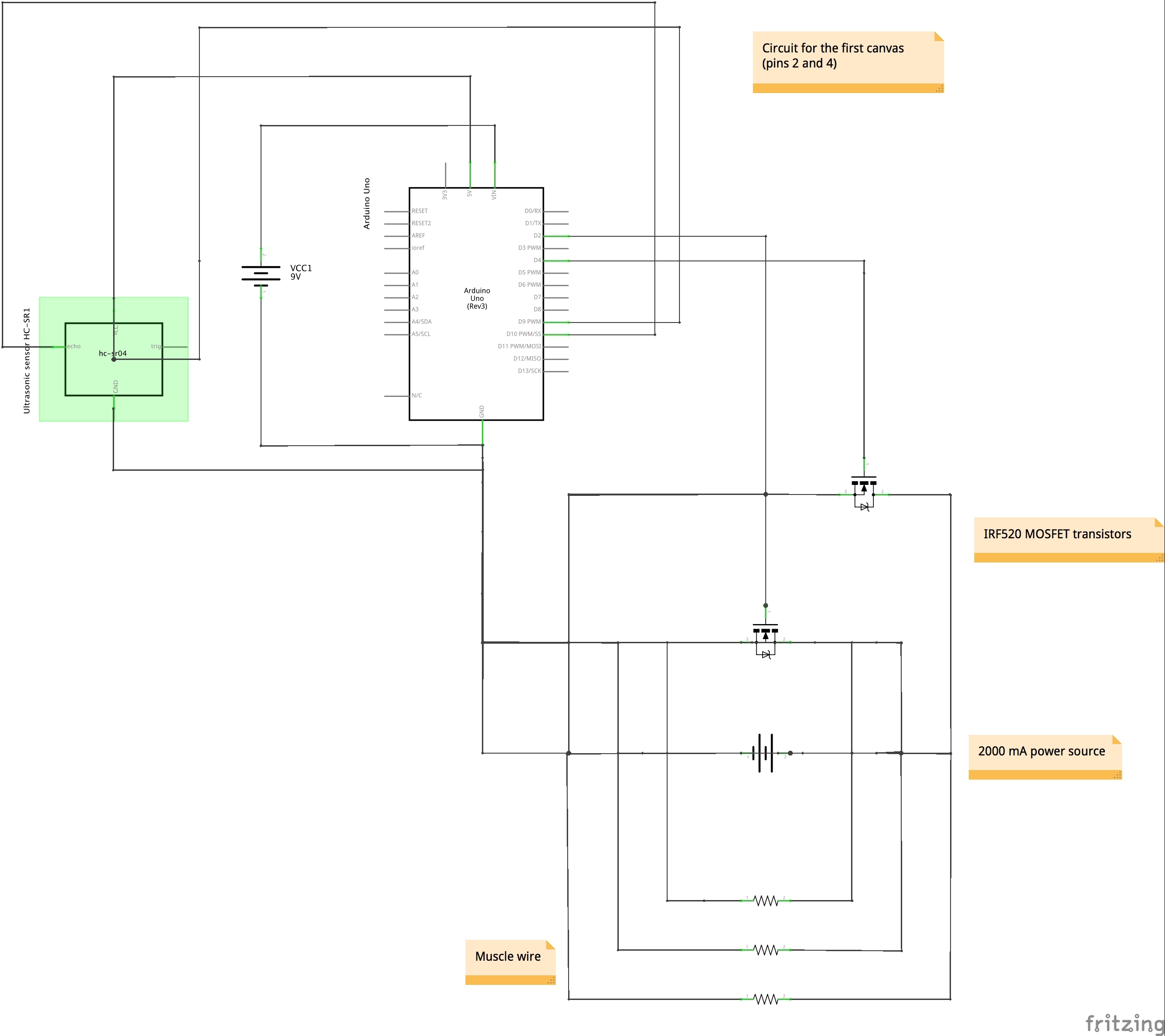
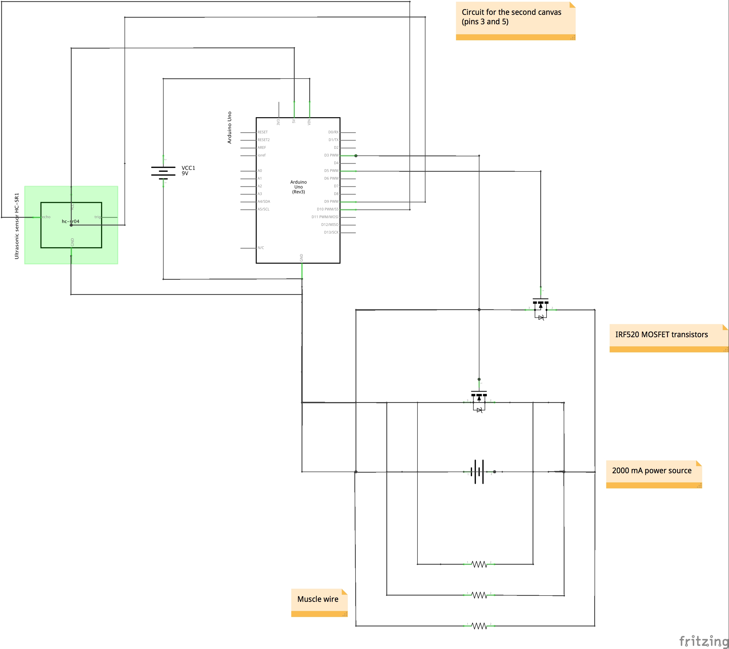
The characteristics of the muscle wire and current requirements combined with lift had to be explored before I could develop the final visual. I considered several ideas including making one large mark, however, I found that the current requirements would be too great unless the power source and circuit were split. I had then planned to have multiple canvases connected to one power source but the current requirements would have been at least 4000mA with a low voltage required due to combining wires. In the end, I decided on two entirely separate canvases with separate power supplies and circuits to keep the current around 1500mA and adapted my code and circuits so the first canvas runs from transistor switches on pins 2 and 4 and the second canvas runs from transistor switches on pins 3 and 5 (schematics for both in the image gallery).
Finally, I refined the code to allow for pulsing. I used LEDs to prepare the code for this and quickly discovered that using delay in the code meant that the lights pulsed in succession rather than simultaneously. Using millis() in for loops instead of delay meant the pulsing could happen simultaneously (see video).
Sources
1) Datasheet for flexinol wire
http://www.robotshop.com/media/files/pdf/flexinol-technical-data.pdf
2) Technical data for flexinol
http://www.dynalloy.com/pdfs/TCF1140.pdf
3) Experiences of working with muscle wire
a) http://fab.cba.mit.edu/classes/863.10/people/jie.qi/flexinol_intro.html
b) https://makezine.com/2012/01/31/skill-builder-working-with-shape-memory-alloy/
4) Pulsing LEDs simultaneously
https://www.baldengineer.com/blink-without-delay-explained.html
5) Using a proximity sensor with Arduino
http://arduinobasics.blogspot.co.uk/2012/11/hc-sr04-ultrasonic-sensor.html