


Physical Computing Portfolio 2020
This is a collection of projects I've made in Term 2: a Drawing machine that responds to mouse x,y coordinates, A synth (unfinished), and device for reading information from plants.
produced by: Wesley Talbot
DrawM
Outline:
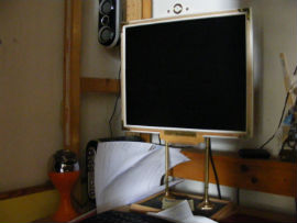
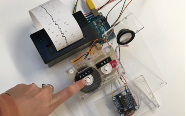
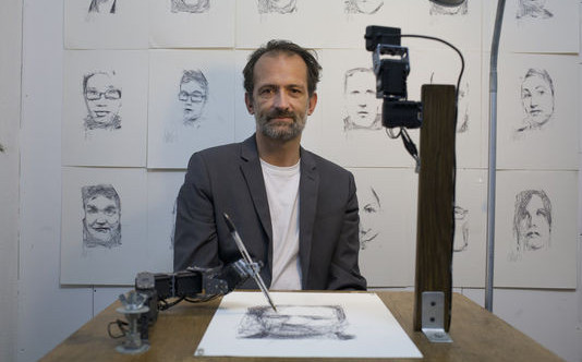
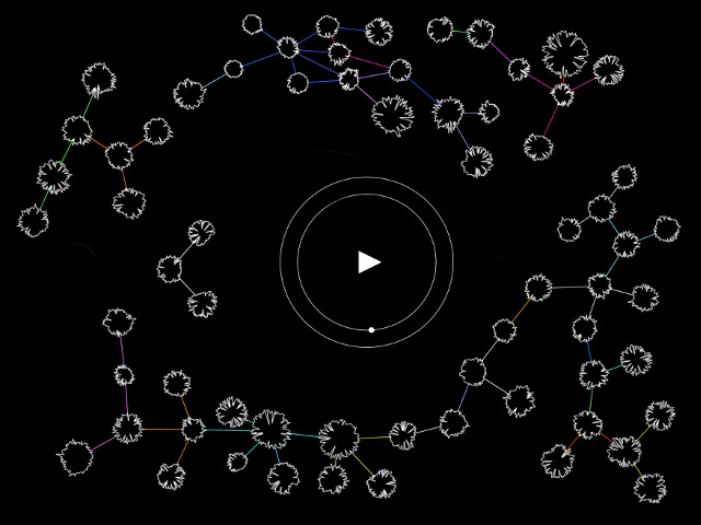
This project has changed its design a few times over the course of a month. It has always been intended to be a functional drawing machine, and in the end it successfully plots the positions from the computer to a piece of paper accurately. I’m continually expanding on the code to make more drawing functions. But once I was able to accurately plot x, y coordinates it became a matter refining the array that stores the list of points.
Starting out:
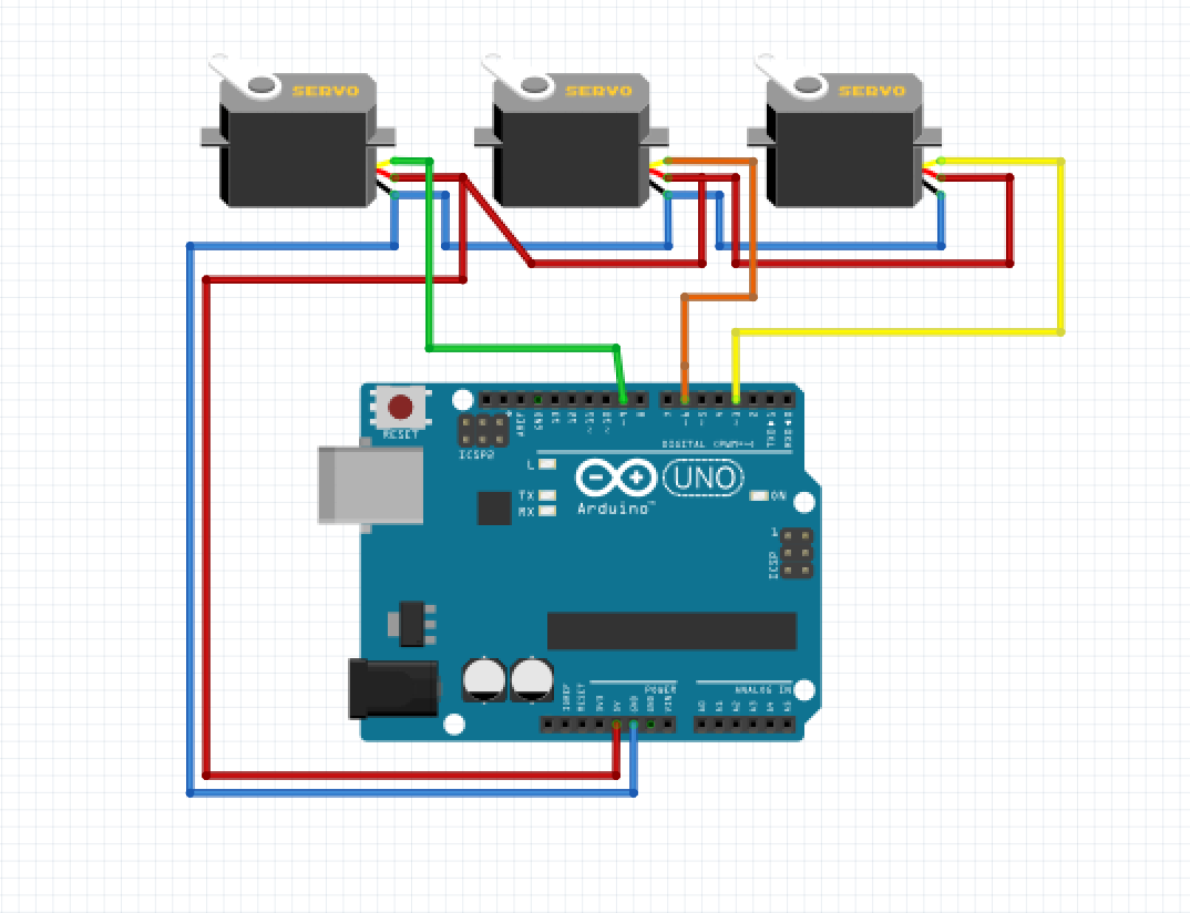
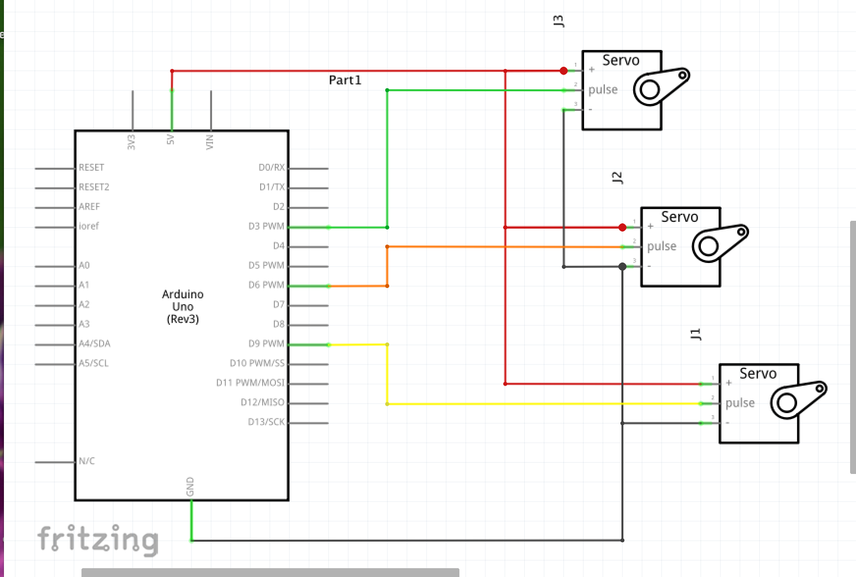
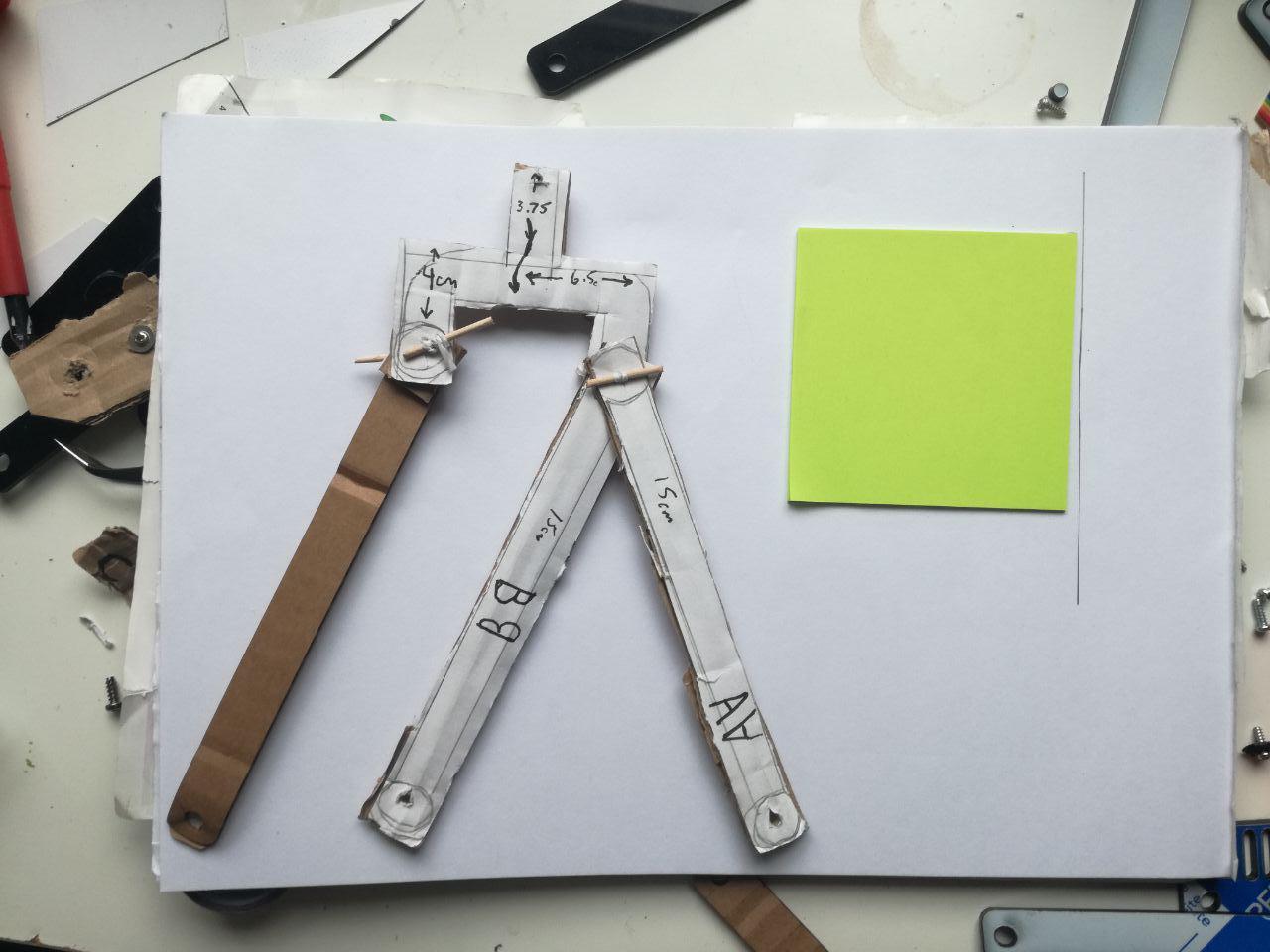
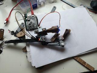
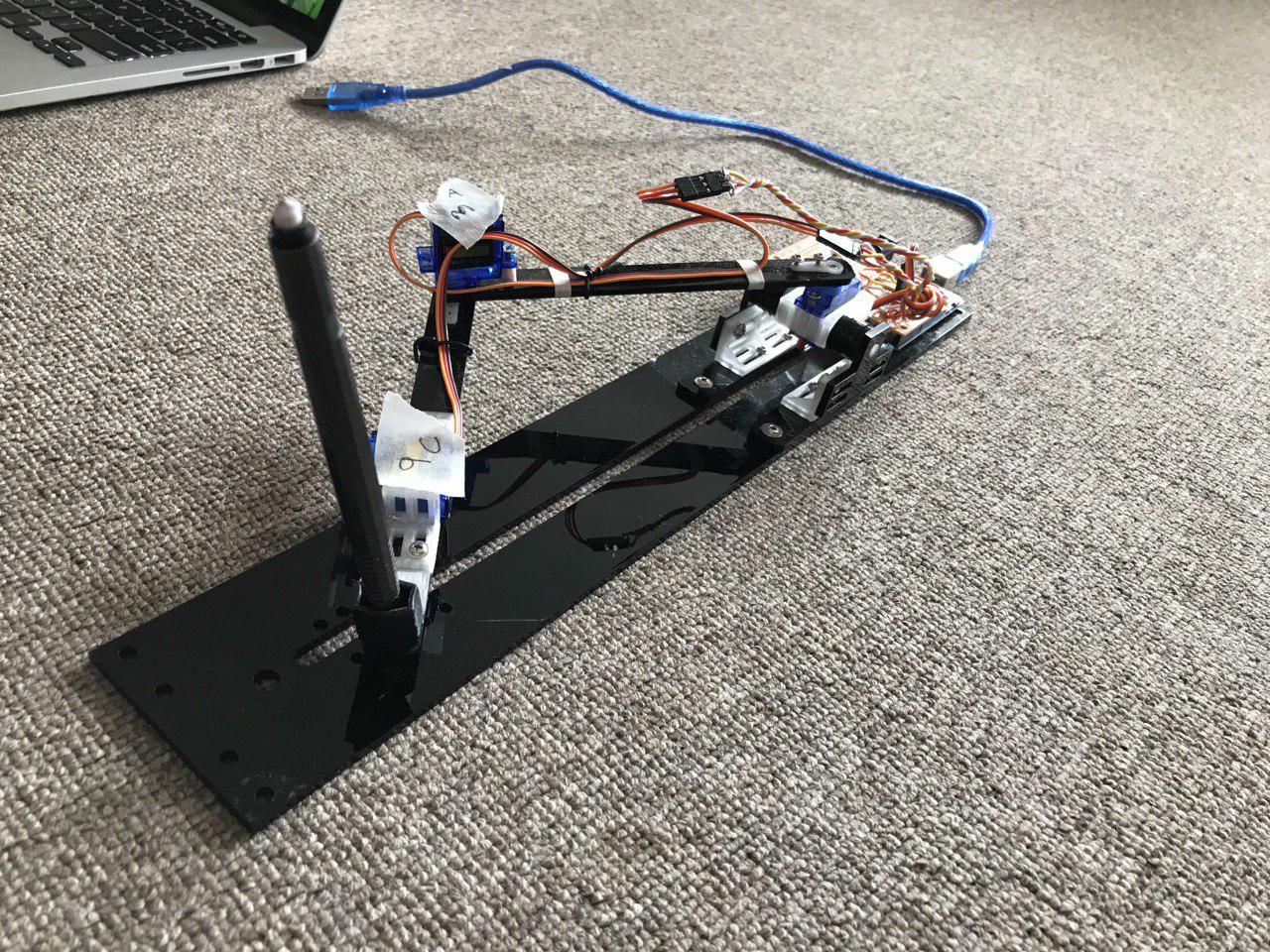
My first idea was to use a kinematically redundant singularity free armature(KRSFA) this was an idea I had come across over the summer and thought might be useful for this project [ref 1]. The reason I thought this could potentially be useful was in the coding, the point being to make it as simply as possible. If I only had to control the distance between motors I figured I could map the entire image to those distances (something I never tested). While working on this first idea during the prototyping phase, I laser cut pieces from scraps of acrylic, and assembled the system with other found parts to temporarily substitute the belt. It was then I came across my first problem, I found that this design needed stronger motors than the servos I was using (later I would also have trouble sourcing a belt system). Fortunately, I later realized the pieces I had initially cut for this design had more use as prototyping devices, and would eventually be used in my final design. Though, they would need to be painstakingly carved with a pen-knife to accommodate the new design. Also because of their make-shift nature I lost some precision due to parts not being properly aligned, fitting well together, etc. It was at this stage I had also 3D printed a hinge piece, for a different idea, that would also be added to this project as a last minute adjustment. From here I changed the design to create an arm with 2DOF. The idea was now to simplify the armature as well as keeping in mind the coding. I thought if I sent the points using OSC data, I would only need to move the drawing pointer to the location and then execute a motion that relied on a physical system. The idea for this came from blending Fourier transformations [ref 2] and computational design of moving characters from Disney [ref 3]. I attempted to make designs by combining different sized rotations. Again, I ran into problems. This time the problem was that I was unable to make a small enough design, or that it would have taken more effort than it was actually worth building a system to make very small circles. At this point I was unable to use resources at the school (laser cutting, 3d printing, etc.) so I decided to make it simple and functional; Which I realize should have been my goal from the start (although to be honest, that’s what I thought I was doing).Here I have the finalized version. Using the 2DOF armature and removing the circular motion, I decided to code in the movement instead. I began by building a system I could control with buttons, to make sure the movements were all working correctly and to see the ranges/values of control. I then had to drop the OSC portion as I could not resolve the OSC data to Serial connection, and when I discovered that both OpenFrameworks and Arduino have a common code example in each, Firmata, I used that to connect the two devices with the code I had written in OFX. The code in OFX is takes the mouse x and y coordinates and translates it into the angles of the servos (0 -180). Now that I am able to connect the Arduino’s control to OFX I will be able to create new functions an operations for it. It is only a matter of deciding what I want its capabilities to be.
Alterations:
My original plan was to laser-cut a box out of wood (or acrylic) to house this which would have made it more stable and look nicer, but that was out of the question once the lab was closed. One idea was to make it have tri-pod legs so that is could be placed onto any surface to draw on. I had also planned to 3D print a pen/pencil/ paintbrush holder. So that it would be more accurate and so that I could change drawing tools depending on what I wanted the machine to do. Currently, it has pieces that I had to re-work to make fit which is affecting its accuracy. I believe once I am able to make the parts I need precisely, it will function much better.
Synth
Outline:
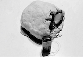
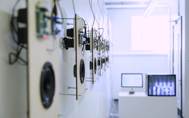
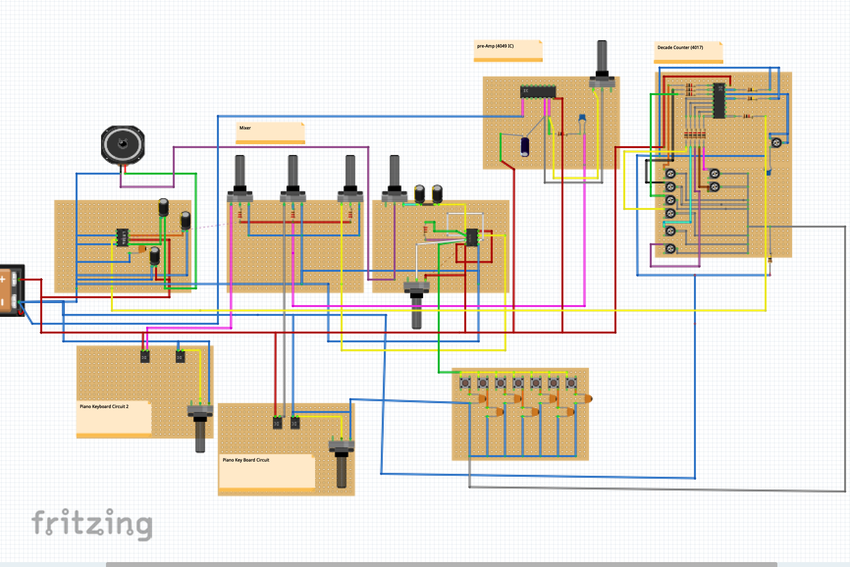
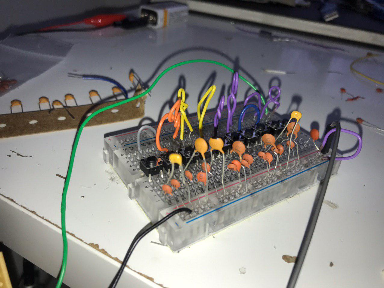
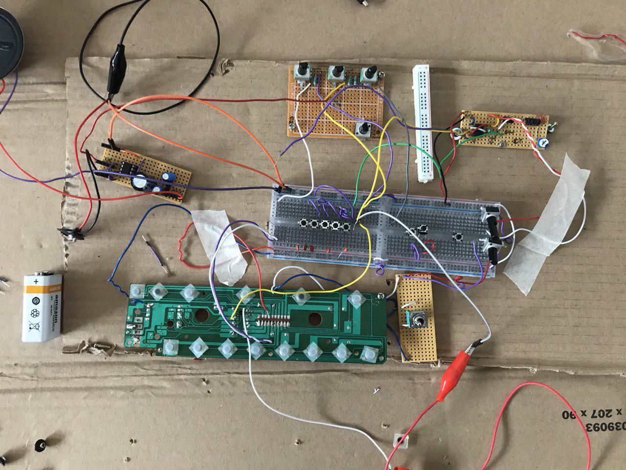
One of the projects I did last term was a hand-held music box that was made from a voltage controlled oscillator using a CD40106BE; the Weaponized synth project came about as an extension of that. After I had submitted it, the professor suggested that it was possible to make oscillators from 555-timer IC’s. I decided to expand on what I had learned by making a larger music instrument, that I am calling a “synth” or the “weaponized keyboard”. I was recommended the book Handmade Electronic Music(HEM) written by Nicolas Collins [ref 1] which I used as a resource in conjunction with the book Practical Electronics for Inventors[ref 2]. In HEM they describe the process of “circuit-bending” as a way to utilize found objects to generate new interesting sounds. I purchased three items for 1 pound each, and my goal was to combine them, along with a self-made oscillator made from a 555-timer into one instrument. I also found a very useful guide on instructables.com which demonstrates several home-made electronic instruments [ref 3], I followed the 555-timer oscillator. The oscillator has a lot of potential, in that, you can make as many tones as you want by adding more buttons and capacitors, but the sound quality can be a little monotone. I think adding distortion to this, or sustain could add something to it. I was able to spend some time playing with them, replacing all resistors with potentiometers and seeing what the outcomes were. The process of circuit bending is not exactly precise, it is mostly trial and error. You won’t be able to make the same effects on every project. That said, with the aid of HEM, I hoped to establish some components that I would be able to apply to every new project, such as: a mixer, pre-amp, looping devices, distortion, amplification, etc. Continuing with the circuit bending, there are a couple of things to look for. One of which is the “timer” which is usually a resistor that has a high resistance (this is from personal experience, and not a rule). Using a potentiometer to adjust this resistor, if found, will speed/slow the instrument playback speed accordingly. If the toy has a demo function (playing a clip of some song), it sounds pretty creepy. Though this is not exactly an unwanted feature. In the long run, I am looking for an instrument to compose strange soundtracks to visuals/videos. It would be nice to have some traditional sounds (piano/instrumental sounds) but also some eerie distorted sounds. I also found adding capacitors in series can create a delay effect. This led to some gritty, obnoxious sounds. I was surprised to find on one instrument that there was a resistor that determined volume control despite not being an option for the toy. I replaced this with a potentiometer and could then control this easily. One of the toys that I was experimenting with unfortunately stopped working after I was making random connections to see their response. My guess would be I accidently connected the VCC to something that should not have had a direct current. Once this stopped working I used it for spare parts, using its LM386 chip, as the amplifier in my overall project. Because I had two instruments working together as one (from the original three), I noticed an odd interference with my oscillator; it only made sound when one of the other instruments was already making sound. Otherwise it was silent. What I should have realized before this was the necessity for a mixer, but having stumbled onto it, I then made a simple mixer (found in HEM page 236) to combine all of the input levels. This worked extremely well. As well as the mixer, I tested a toggle switch to create different effects on the timing of each device, so that when it is in its “standard” position you can simply control the resistance, but once it is in its “active” position you have a series of “effects”. This would have been accomplished by a series of switches and different combinations of resistors and capacitors being selected ultimately running through a decade counter. Overall, I am inspired by the circuit bending done on the YouTube channel Look Mum, No Computer [ref 4]. He uses found materials and makes things like a church organ made of Furbies (the very popular at one time and very annoying toy).It is also worth mentioning that I have grown up in a family where music was always played, my mother played piano and my father guitar. Designing unique instruments seems to be the perfect intersection of my newfound tech interests and lifelong passion.
Alterations:
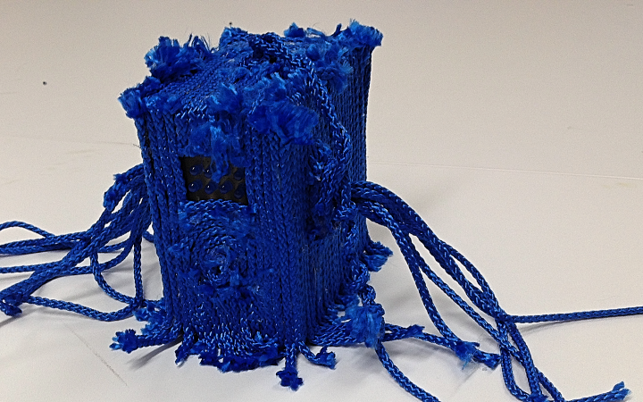
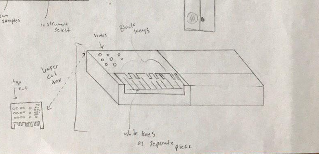
My initial design included laser-cutting two boxes to put these into, with a 3D printed hinge connecting them together. I would layer the “keys” so that it would function as a regular piano keyboard. I had prototyped the design out of cardboard to approximate dimensions and refine the layout. The end result is completely shabby but does showcase the design; a collapsible keyboard that would be uniquely my own. I was intending to leave space within, and on its surface for new components to be added, that way it would have a longer life, being able to change and accept new components. More importantly, I had hoped to build a step-counter, using a CD4040 (as outlined in the HEM) and a pre-amp using a 4049IC (also outlined in HEM )but was unable to get the parts for it. I also had difficulty sourcing enough capacitors in differing capacitance for the 555 oscillator, which limited the range of notes it could produce.As mentioned before I initially had a keyboard with much more functionality that I was hoping to use in this project, but through different test I burned out the main IC, and it became scrap parts. I bought this for 1 pound at the local thrift shop, and if I had been able to look around I would have tried to purchase a similar one (or the same model if possible). Unfortunately, all non-essential stores closed and I was unable to look for replacement parts/toys. This keyboard would have been one half of the total keyboard, the idea being to modulate it with looping functions and distortions similar to the other half. Furthermore, if I had been able to obtain more items to experiment with I also would have liked to attempted merging found items together. There is a whole area of circuit-bending that I would be interested in practicing if given the time and materials.
Leaf Reader
Outline:
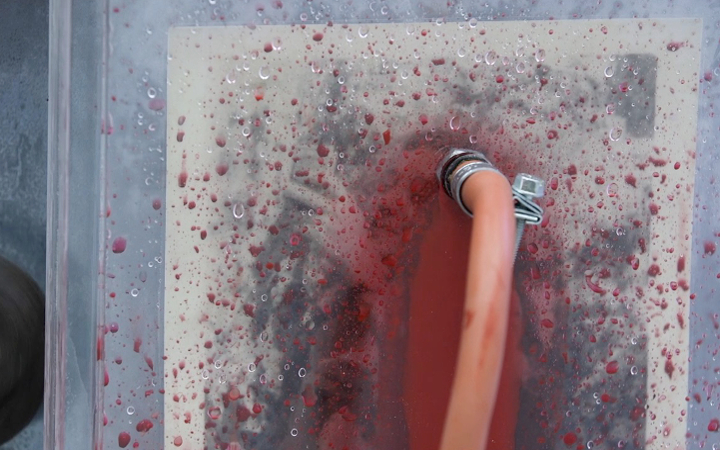
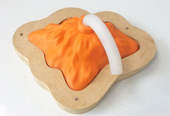
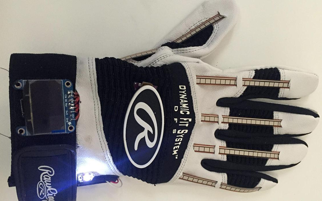
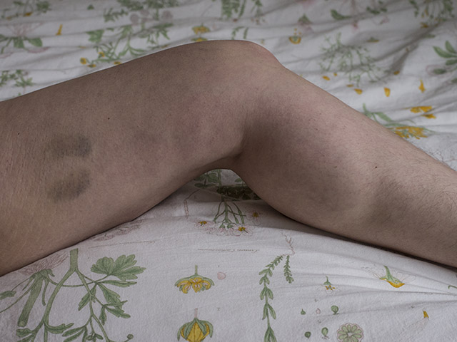
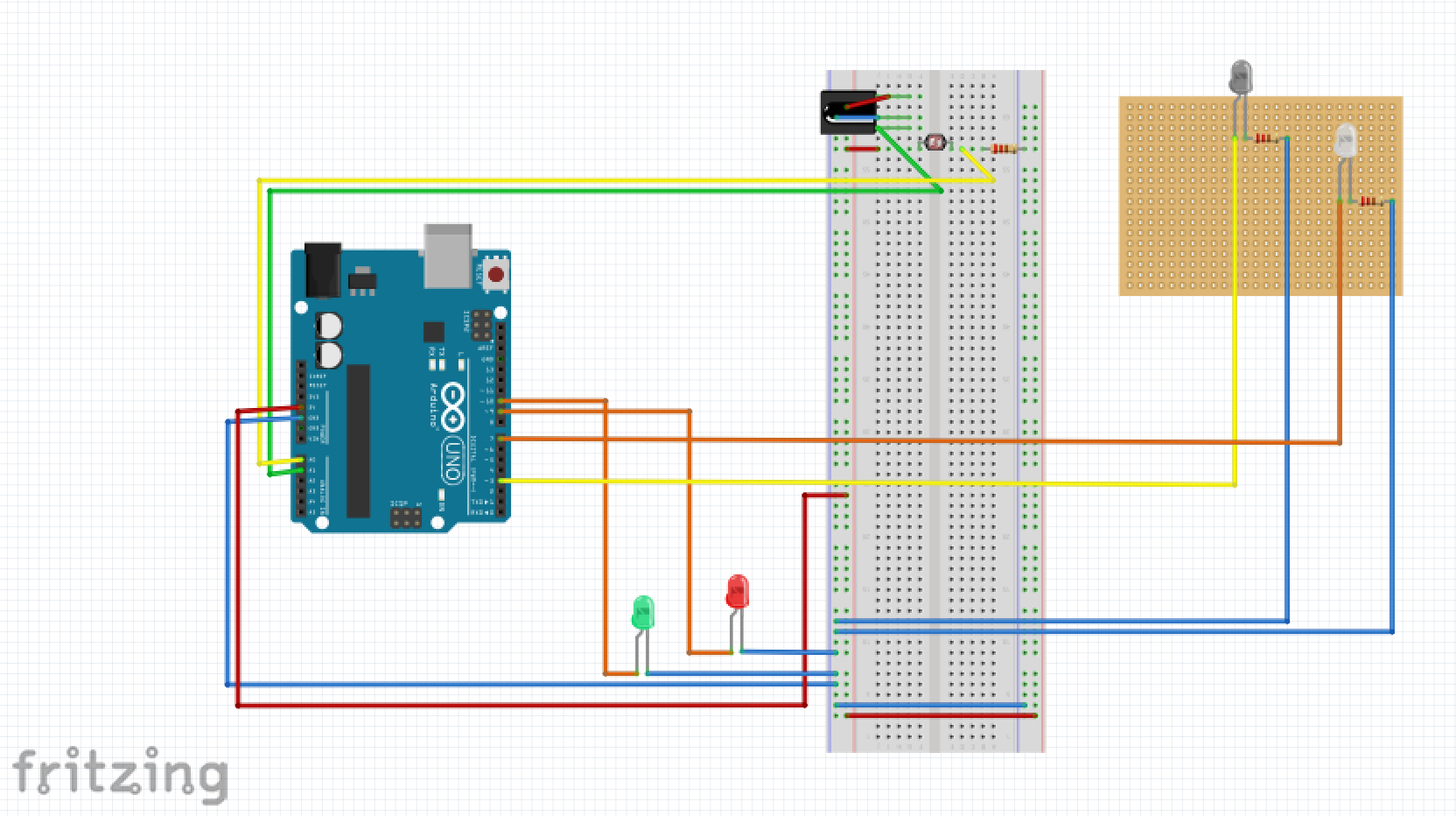
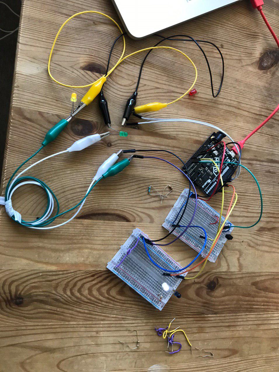
This project was inspired by pulse oximetry (PO), which is a method for reading oxygen levels in blood using light. I have been interested in learning about how to use infrared light specifically because it seems to have many practical applications. Looking into pulse oximetry I got the idea to read the values of oxygen in the leaves of house plants and use that data for some expression of the plant. (I have also taken to gardening during the lock-down, so it seemed a likely subject.) Creating an outlet for the plants to communicate their state. The design was conceptually modelled after the PO meters that one generally wears in the hospital on their finger. The design I have here, would clip to the leaf of a plant; focusing and limiting the amount of exposure to environmental light therefore controlling the possibility of exposure to light pollution resulting (i.e. noise). As one light would be from a white LED, this would not affect the reading by the infrared sensor. Similarly, the infrared would not affect the overall reading of the light sensor. By using two forms of lights I can ensure something closer to accuracy and consistency by comparing the two data-sets against one another. There would also be a stand, laser cut, to hold the device in place so that readings could be taken over long periods of time and stay somewhat consistent. For the code I edited the Analog Read Serial to input the IR and LED light values[ref 1].
Alterations:
I had intended to 3D print a housing device to hold the infrared and White LED light, as well as the infrared receptor and light sensor. This clip would have been printed in black in a further attempt to reduce light pollution to ensure the most accurate reading possible. I had planned to laser-cut the stand which would be able to be inserted into soil, having an adjustable height range.
References
DrawM:
1. Kinematically Redundant Armature, https://www.youtube.com/watch?v=_vp1ELEtDN4
2. Fourier Transform, https://www.youtube.com/watch?v=r6sGWTCMz2k&t=565s
3. Disney , Computational Design of Moving Characters, https://www.youtube.com/watch?v=DfznnKUwywQ
4. https://docs.opencv.org/master/d4/d8c/tutorial_py_shi_tomasi.html
Synth:
1. Collins, Nicolas. Handmade Electronic Music the Art of Hardware Hacking. 2nd ed. New York London: Routledge, 2009. Print.
2. Scherz, Paul, and Simon Monk. Practical Electronics for Inventors. Third Edition / Paul Scherz and Simon Monk.. ed. 2013. Print.
3. https://www.instructables.com/id/Battle-of-the-Bands-555-Timer-Edition/
4. Look Mum No Computer, https://www.youtube.com/channel/UCafxR2HWJRmMfSdyZXvZMTw
Leaf Reader:
1. Arduino Read Serial, https://www.arduino.cc/en/Tutorial/AnalogReadSerial