


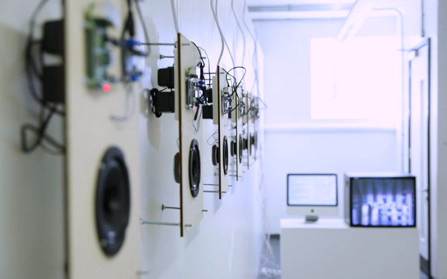


Twitching Hexagons
If you get too close - these strange hexagons will go a bit crazy. Back off!!
produced by: James Tregaskis
Introduction
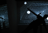
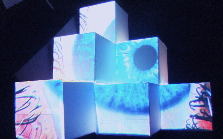
Why 16 servos? Certainly, more than is sensible for a first project. However, this all started with my interest in using a ESP8266 WiFi module in ‘promiscuous mode’ to capture WiFi traffic [1][2][3]– each of the 15 channels (not 16!) would be mapped to the relative vertical position of 3D printed cubes.
I had a minor setback during the latter part of the term with my laptop, stupidly writing over my Windows portion of the drive with Mint. I had backed up most of my work but lost the intermediate recordings between the proposal and after the prototype. I therefore lost my initial Fritzing and Arduino code work.
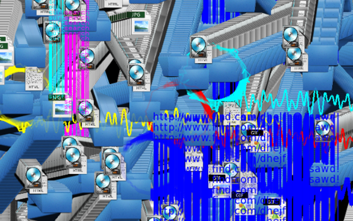
The initial idea was for the ESP8266 to look for the appearance (and disappearance) of MAC addresses and add up the cumulative signal of devices connected on each WiFi channel. To do this, you set the ESP8266 into ‘promiscuous mode’ to listen to all WiFi traffic[4]. This would initiate movement in each servo, one servo per channel.
To be honest, I became very distracted with the code using the ESP8266 and this impeded my progress with the ‘physical’ side of the project, thankfully, a prod from Saskia awakened the need to change course. I also was not happy that a given WiFi environment would not initiate sufficient changes for movement into the physical installation.
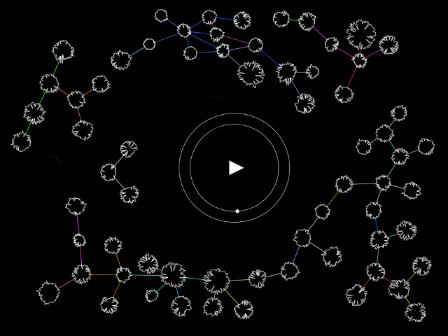
Video of project
https://youtu.be/K9of0bli7dQ
Materials and methods
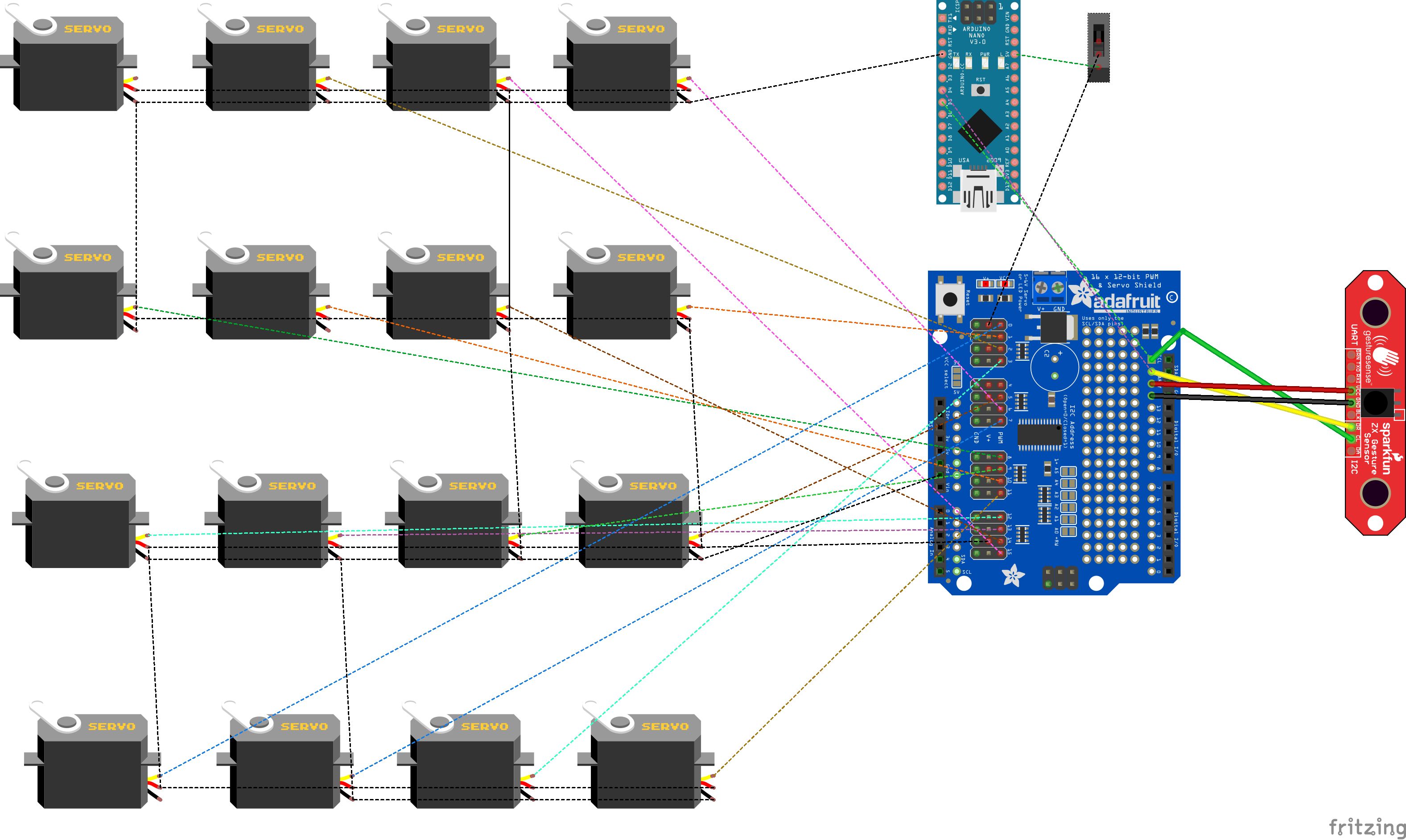
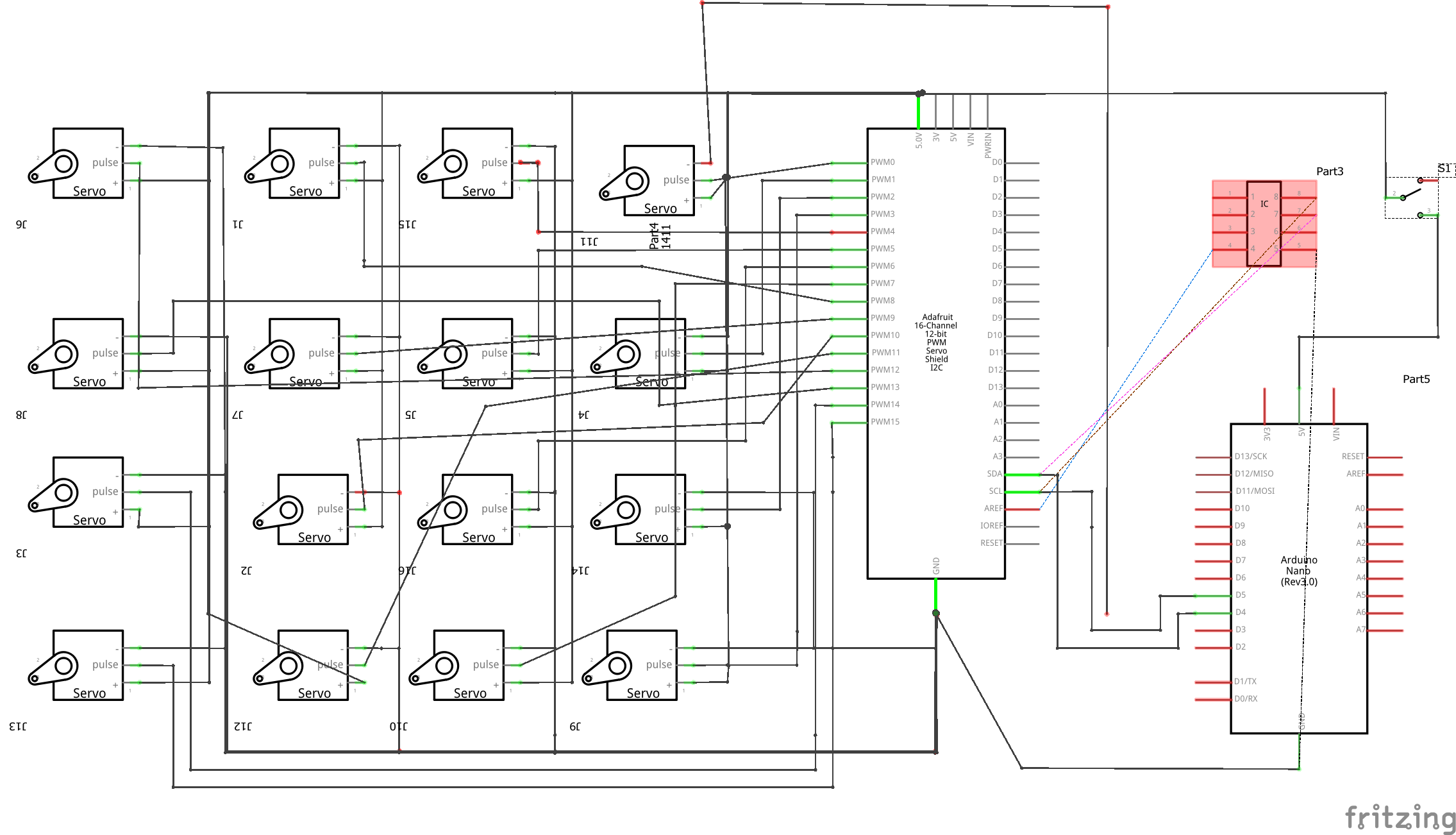
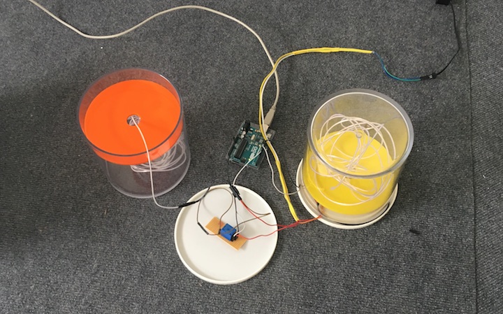
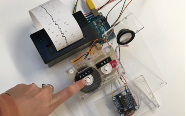
I liked the idea of multiple servos and some form of sensory input – How best to control many servos? I soon realised it would be beyond the Arduino’s capabilities to drive 15 or 16 servos. Adafruit had the answer; in 2013 they produced a 16-channel servo shield[5]. They also do a similar 16 channel motor shield as well. The servo shield is controlled by the I2C serial protocol, you can even stack chain up 62 shields to control 992 PWM outputs, also one or more I2C protocol sensors – or even oled or LCD.
The good thing is, the shield does not ‘hang up’ the loop running in the sketch, thus delaying the Arduino, as it would do - if driving the servos directly off the digital pins.
I used a gesture sensor [6] by Sparkfun. This sensor can detect right-left movement as well as movement coming towards it (in the Z plane).
Using this number of servos creates far more load than a tiny Arduino (in my case, a Nano 3) could deliver. It turns out, to drive 16 servos (5v each) would require a 10 Amp power supply to comfortable cope with possibly all 16 operating at once.
I was tempted to use another servo shield in the project – for possible expansion to incorporate simple PWN operation of pulse with modulated LEDs. I did not have time for that in the time, as I may extend the project soon to include this. I included the second Adafruit shield in the physical build where I intend to add some more (LED) action.
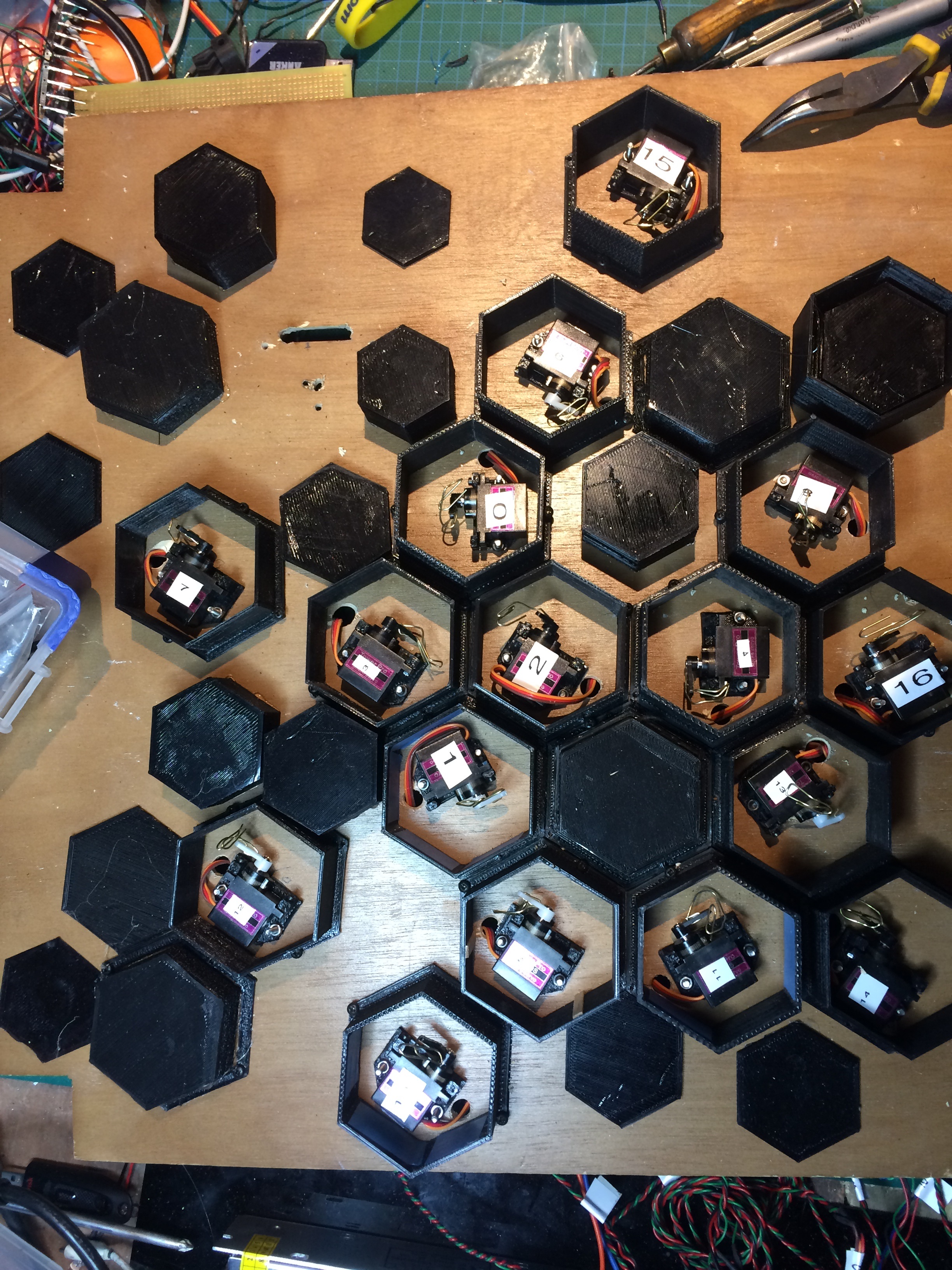
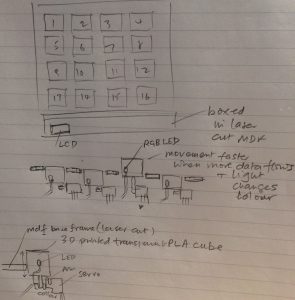
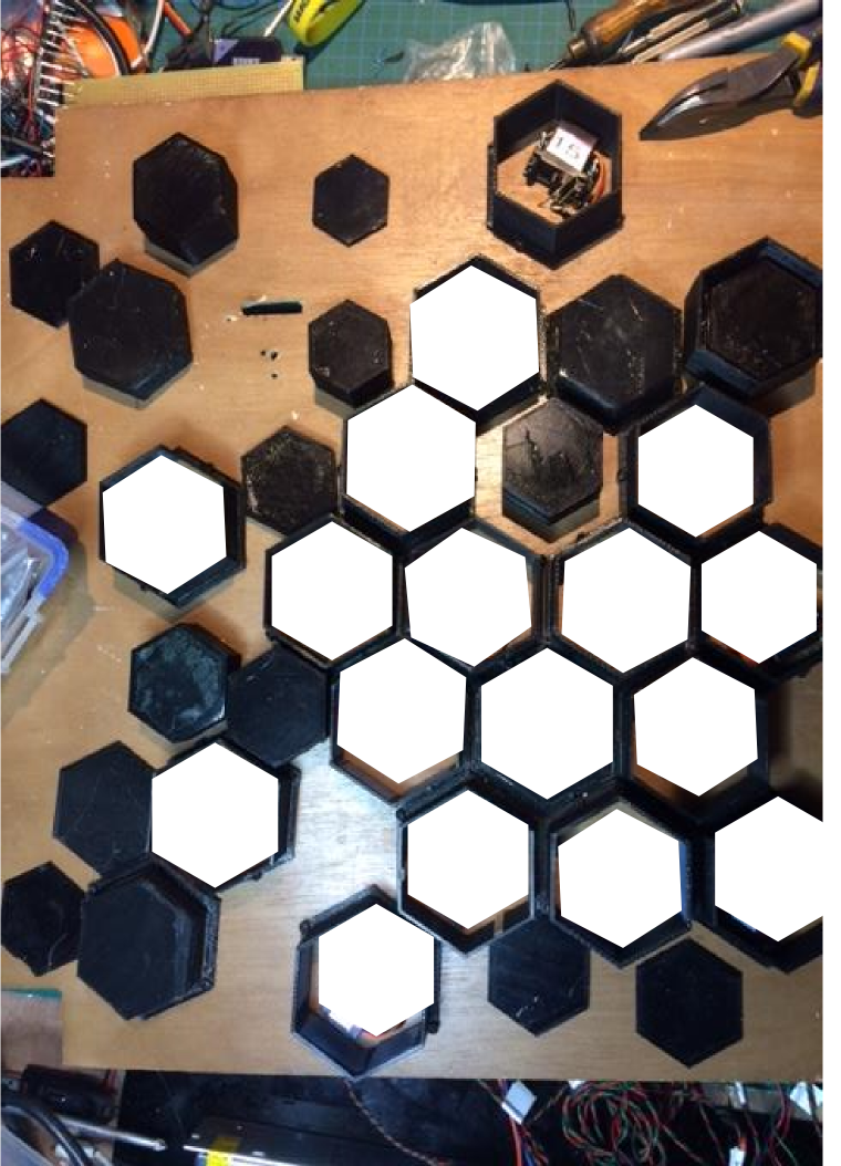
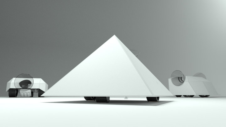
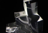
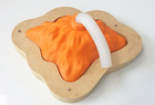
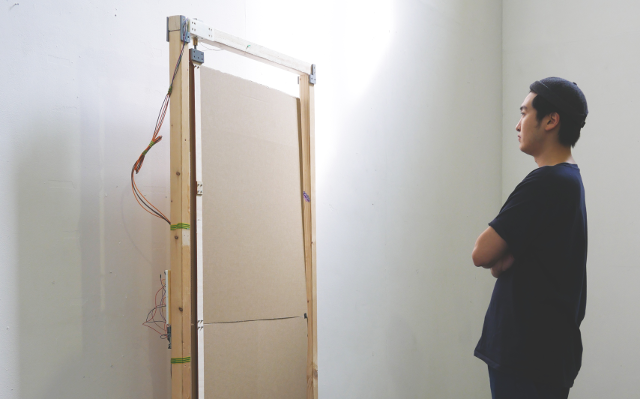
My array of cubes in the proposal drawings [7]changed into hexagons, also, I wanted a more interesting configuration than straight rows and columns of twitching cubes.
Using my home built trusty Prusa i3 3D printer I designed my hexagons to be mounted independently on a plywood base. This required:
1) The enclosure for the hexagon
2) The hexagon itself
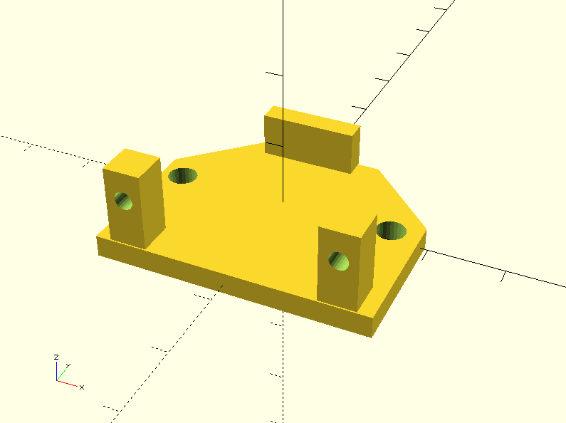
3) The support for the servo
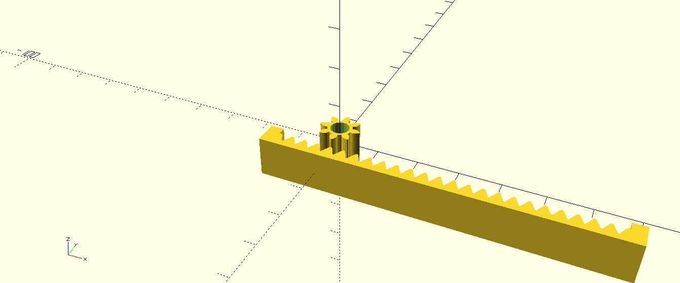
4) Possibly some rack and pinion mechanism
I opted on a design which enabled me to lay the hexagons out in a pleasing way without reliance on a laser cut enclosure. I wanted to use the shapes of the printed objects to be prominent as part of the design. The cables and electronics are laid bare – it would be a simple next step to mount the board onto a fully enclosed box with the electronics fully enclosed. All told, the printing took approximately 72 hours and 0.75Kg of black PLA.
Time marched on, I had samples of the rack and pinion mechanism derived from the excellent sketch by Leemon Baird[8] based on Public Domain Parametric Involute Spur Gear sketch.
An improved re-working of the vertical operation is on my ‘to-do’ list. In the end, I used paperclips purchased from Rymans attached to the servo arms to amplify the movement under the hexagons.
Arduino sketch
The sketch is simple, I preferred to use a function which rocked the servo back and forth, in a loop from maximum to minimum position and back, rather than mapping the proximity of the visitor’s movement directly from the sensor. I felt this gave a ‘livelier display’, beyond the less interesting prospect for the onlooker of merely controlling movements up i.e. the closer you get…
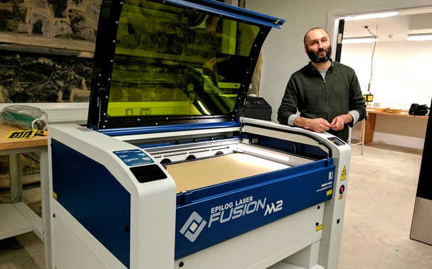
3D printing
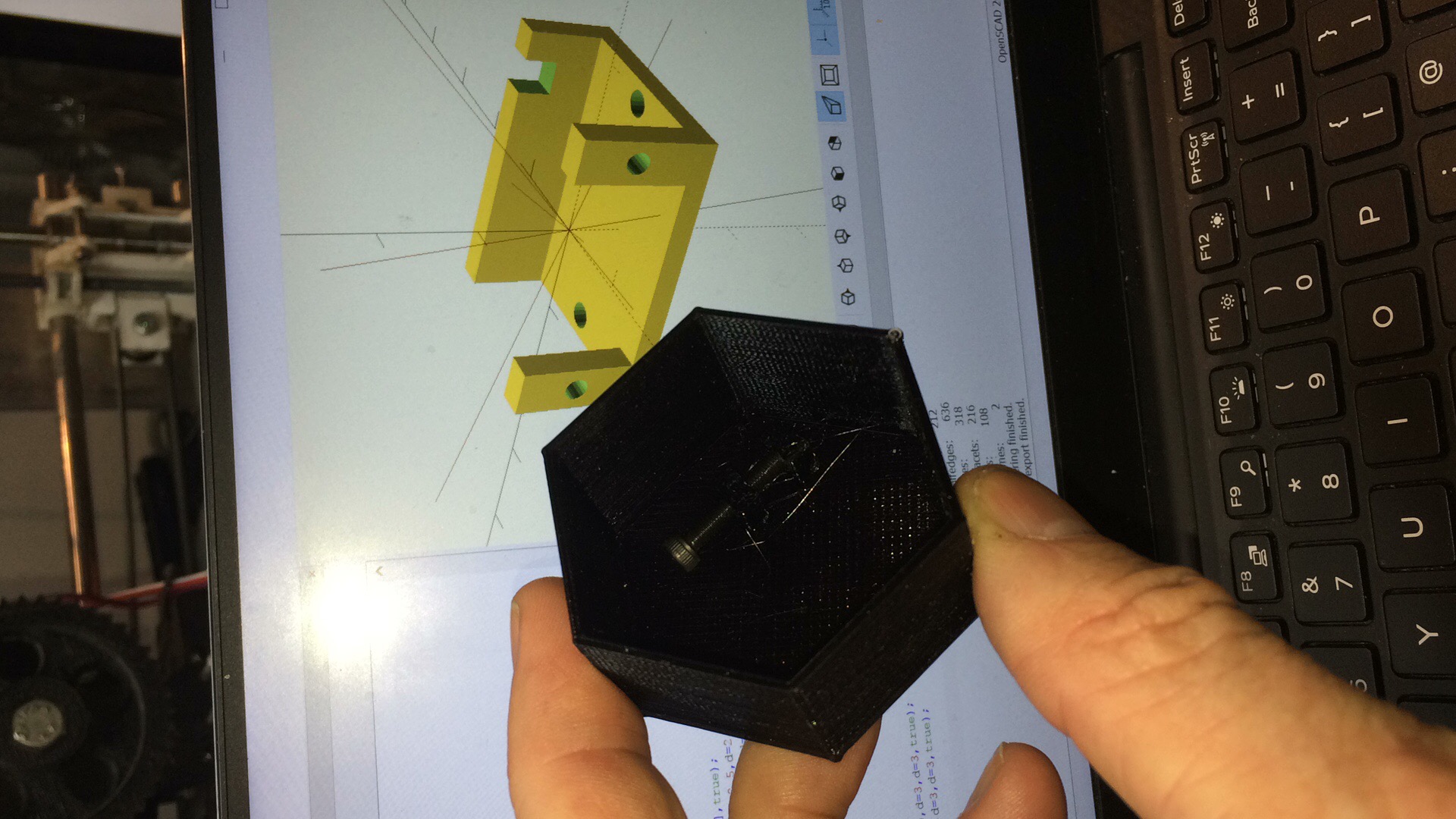
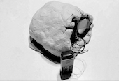
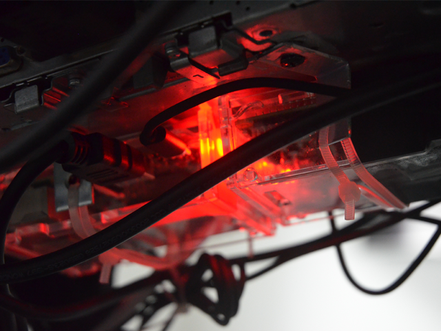
I am fortunate to have built a 3D printer already. I used it extensively in the project; it freed me up to scale up production of parts, although the excellent printers at Hatchlab were superior to mine as they provided a higher finish, time became of the essence, particularly with so much to make as I could run the printing throughout the night (at slow speeds). At one point, the printer ran for 3 days non-stop. One small breakdown on the way, the connectors on the Ramps board loosened due to heat expansion and contraction causing loosening of the screws, power loss, soon remedied (see photo).
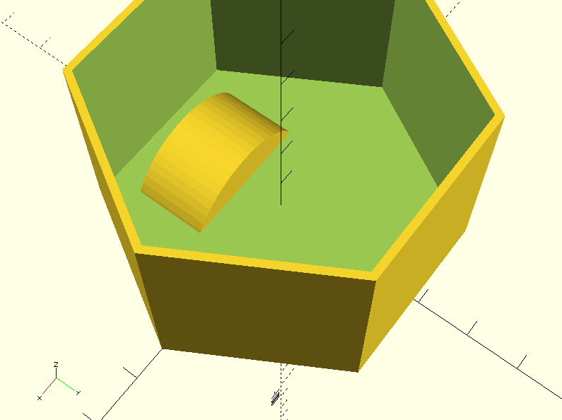
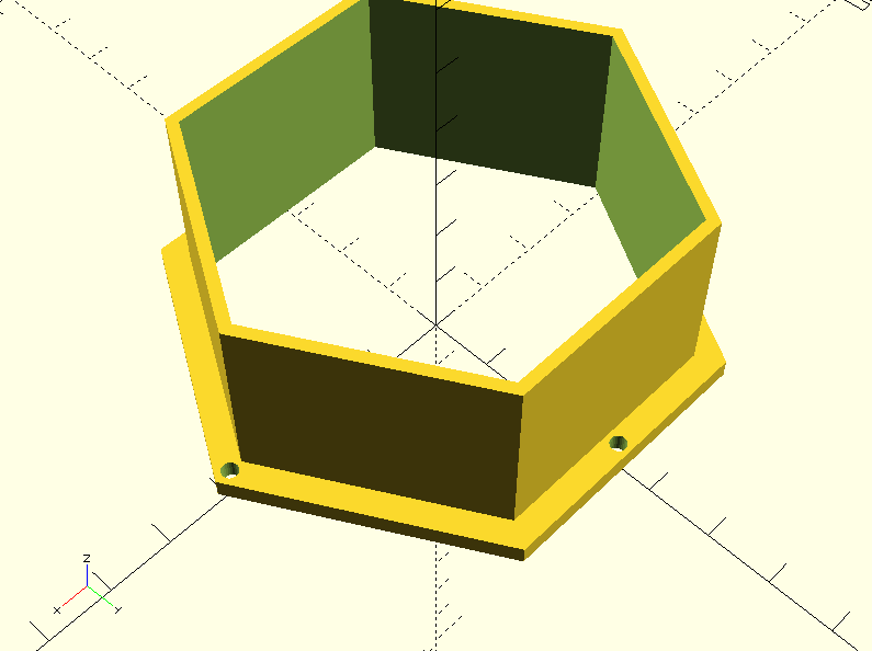
I used OpenScad [9] to draw up the hexagon, enclosure and servo support. (see gallery for images of printed components)
Materials:
64 x 10mm self-tapping screws
40 x 20mm s/s 3mm hex head bolts
40 x 20mm s/s 3mm nuts
32 x 20mm s/s 1mm hex head bolts
32 x 20mm s/s 1mm nuts
0.75 Kg PLA (approximately)
1 x Nano 3
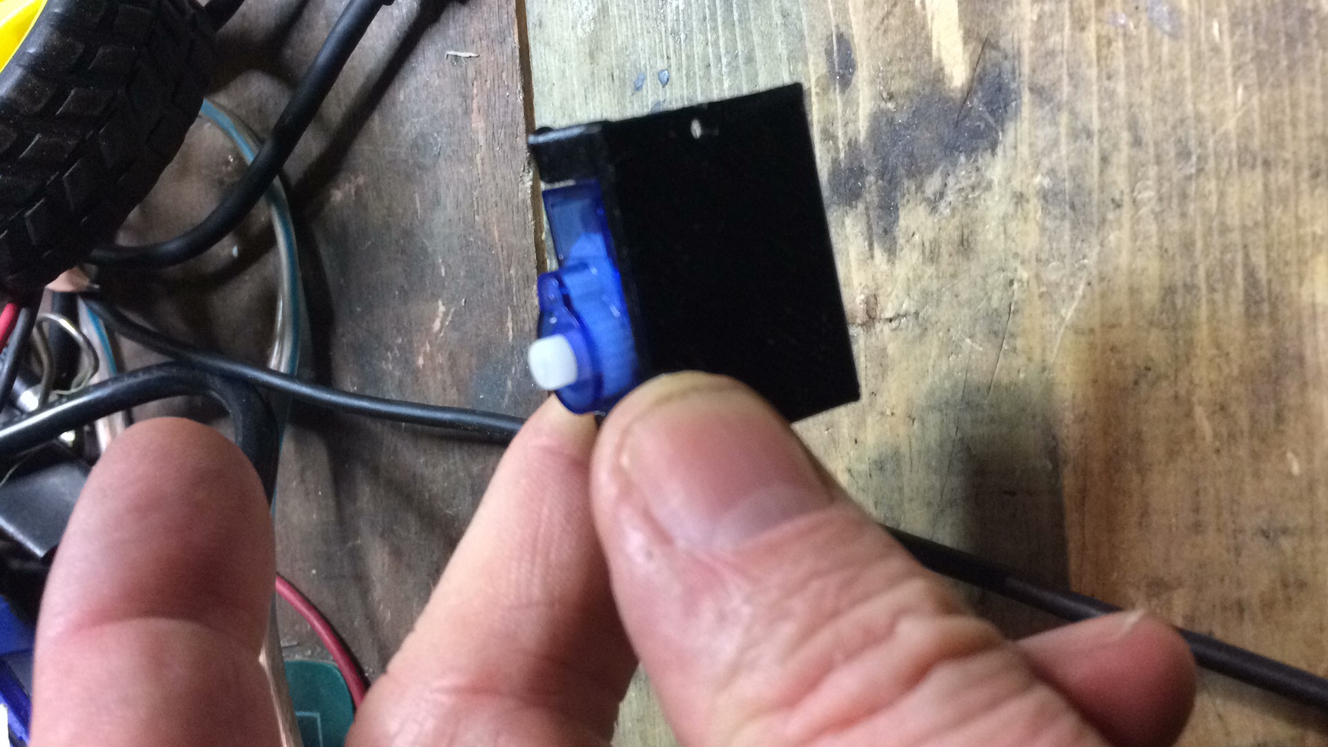
1 x micro slide switch to shut controller off
2 x pairs of connecter plugs; male and female
Mini stripboard to solder connections to sensor
30 M of connector wire
1 x Adafruit 16 channel 12 bit servo shield
1 x Sparkfun gesture sensor
1 small stripboard
50 cm x 50 cm waste offcut of plywood
1 x KeerSen DC 5V 10A 50W Switching Power Supply Regulated Transformer w/ Short Circuit and Over Current Protection (5V10A)
16 x MG90S Metal gear servos (knock-off copies of originals I think)
(refunded for terrible plastic gear servos – avoid!!)
I had some initial problems with plastic servos, replacing them with metal geared servos, these perform very well. This hampered my demo of the working project. I installed them soon after and had the project finished.
Care was taken to extend the servo wires and label everything up clearly. 16 times the birds nest of wiring!
Conclusion
I was slow to get my concept to work as I was not happy with my original idea. I was also seduced by offering a scaled-up project, but I had high hopes to create something ‘fun’. For my next project, I think I will spend more time planning it and disciplining my self to reduce manufacturing time to a more manageable level.
I have learned a lot in the journey to produce this work, more than the lab work, and I hope to refine this piece to run more smoothly (mechanically) with more behaviours.
References
[1] The Glass Room Exhibit Oct-Nov 2017 “Unintended Emissions Julian Oliver & Bengt Sjölén & Danja Vasiliev
The Critical Engineering Working Group @julianOliver / @bengtsjolen / @k0a1a
[2] https://youtu.be/9_Zw_Mls98c
[3] Github.com Expressif/Arduino-esp32@Igrr IvanGrokhotkov (www.doit.com)
[4] https://www.hackster.io/rayburne/esp8266-mini-sniff-f6b93a Article by Ray Burnette Mini Sniff
[5] https://www.adafruit.com/product/1411
[6] https://www.sparkfun.com/products/13162
[7] https://tregaskis.net/project-end-of-term-1/
[8] 2011, Leemon@Leemon.com Public Domain Parametric Involute Spur Gear (and involute helical gear and involute rack
[9] http://www.openscad.org/