


DrawBots
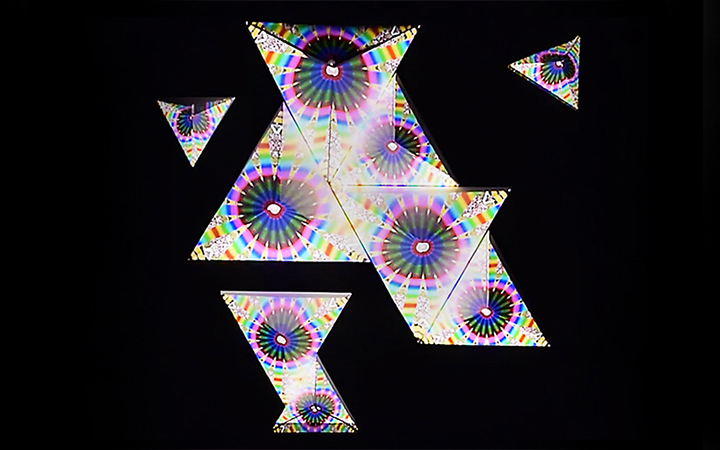
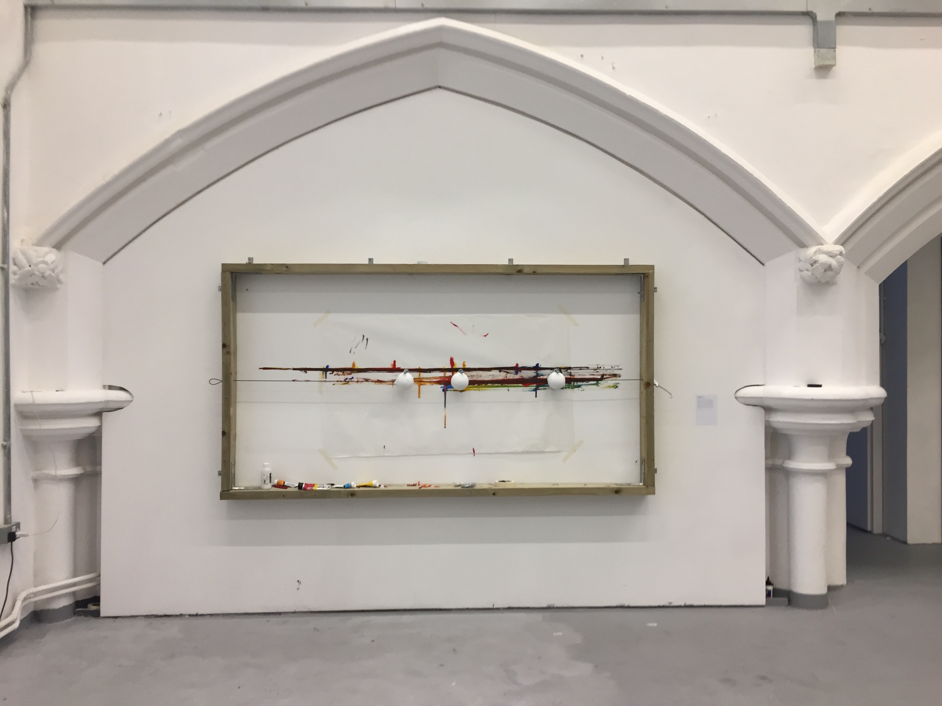
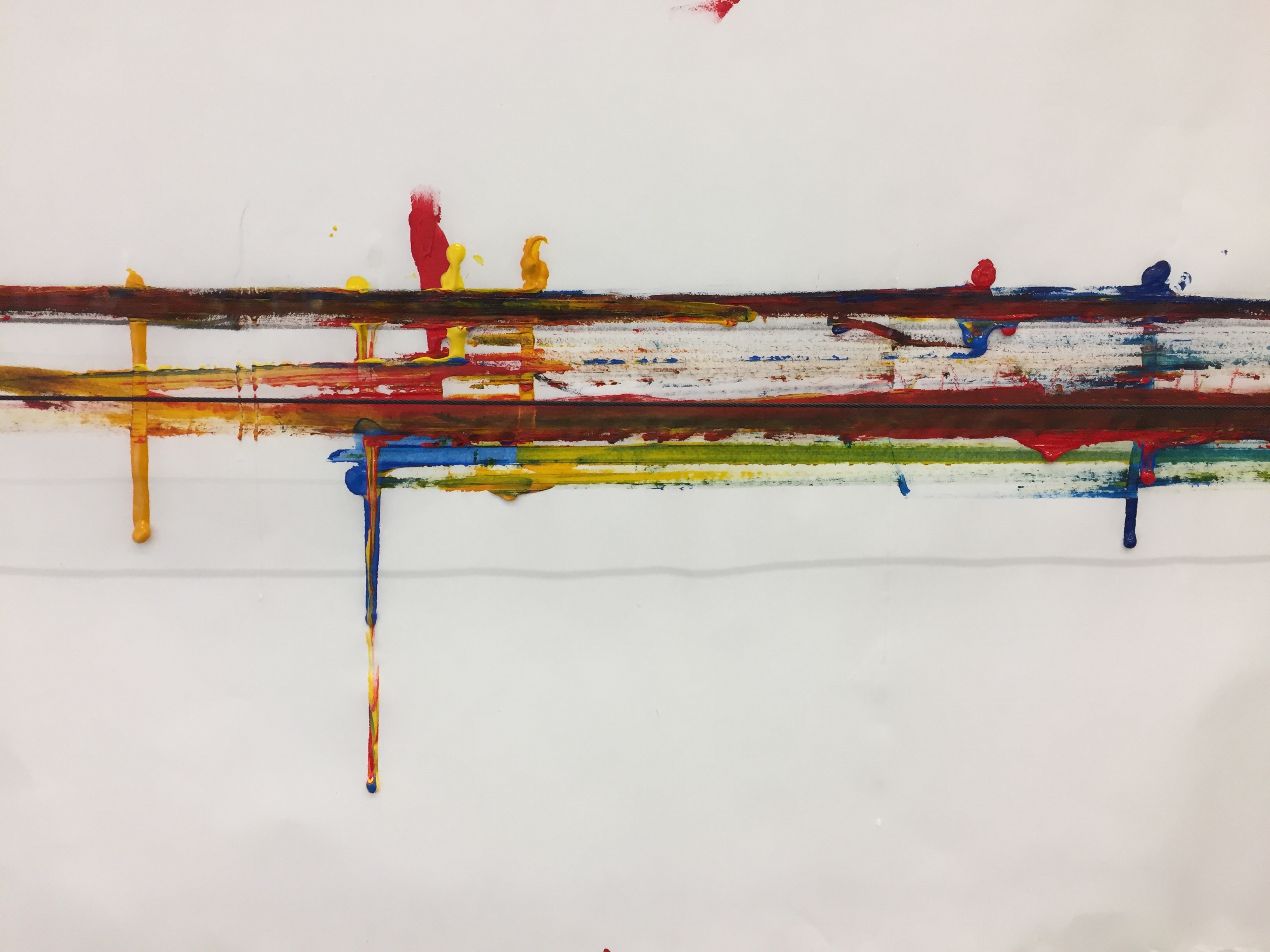
DrawBots are a physical manifestation of my process-based fine art practice which seeks to break drawing down to its essential components and reconstruct these elements through serial actions. DrawBots materialise constructive systems and display an exploration of the presence and influence of the artist in aesthetic and creative decisions.
Laura Traver
Introduction
DrawBots were originally envisioned as independently operating art agents that make art by communicating with each other. In practice, they became objects that made art under my direction but not necessarily within my control. As such, they became something more like my tools.
Concept and background research
DrawBots bring my fine art practice together with computing. The engaging simplicity of the idea of Paul Klee that "a line is a dot that went for a walk" and his concept of an "active line without a goal" in Pedagogical Sketchbook continue to influence me as I play with the idea of how the dot goes for a walk. In this case, through robots. The DrawBots are a reflection of my fine art practice in which I fracture drawing into what I call elements of drawing which include time as both duration and intervals, materials, gestures, and physical position and then reconstruct these elements to create work. At one point, my aim in so doing was to eradicate the artist, but this is an impossible task. In my practice now, this impossible task has become a constructive game or tool and the DrawBots are physical representations of the elements.
Systems art and artists such as Sol LeWitt and Richard Long have highly-influenced my fine art practice and the development of the DrawBots. The work of artists working with robotics and my observation of their frequent pursuit of the extraction of the artist from the art-making process through robotic systems, such as Leonel Moura, has also influenced the DrawBots. Unlike some of these artists, I do not take the extraction seriously and instead regard it as a way to bring together fine art questions with new methods, materials, and questions posed by computing. I have also been influenced by the works of people who work more collaboratively and, potentially, expressively with computing and physical computing such as Michael Quantrill who set up a whiteboard with a laser matrix and connected this to a computer to fuse the two in 2012 (ref 22) or Tom White’s Digital Finger Painting in which a medical bladder was wire up and filled with soy sauce to give an approximation of touching paint while on a computer (ref 23).
Technical
The Shape
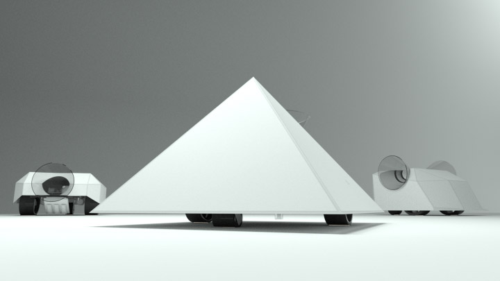
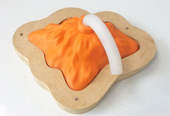
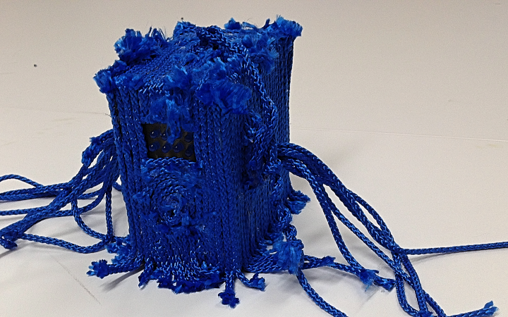
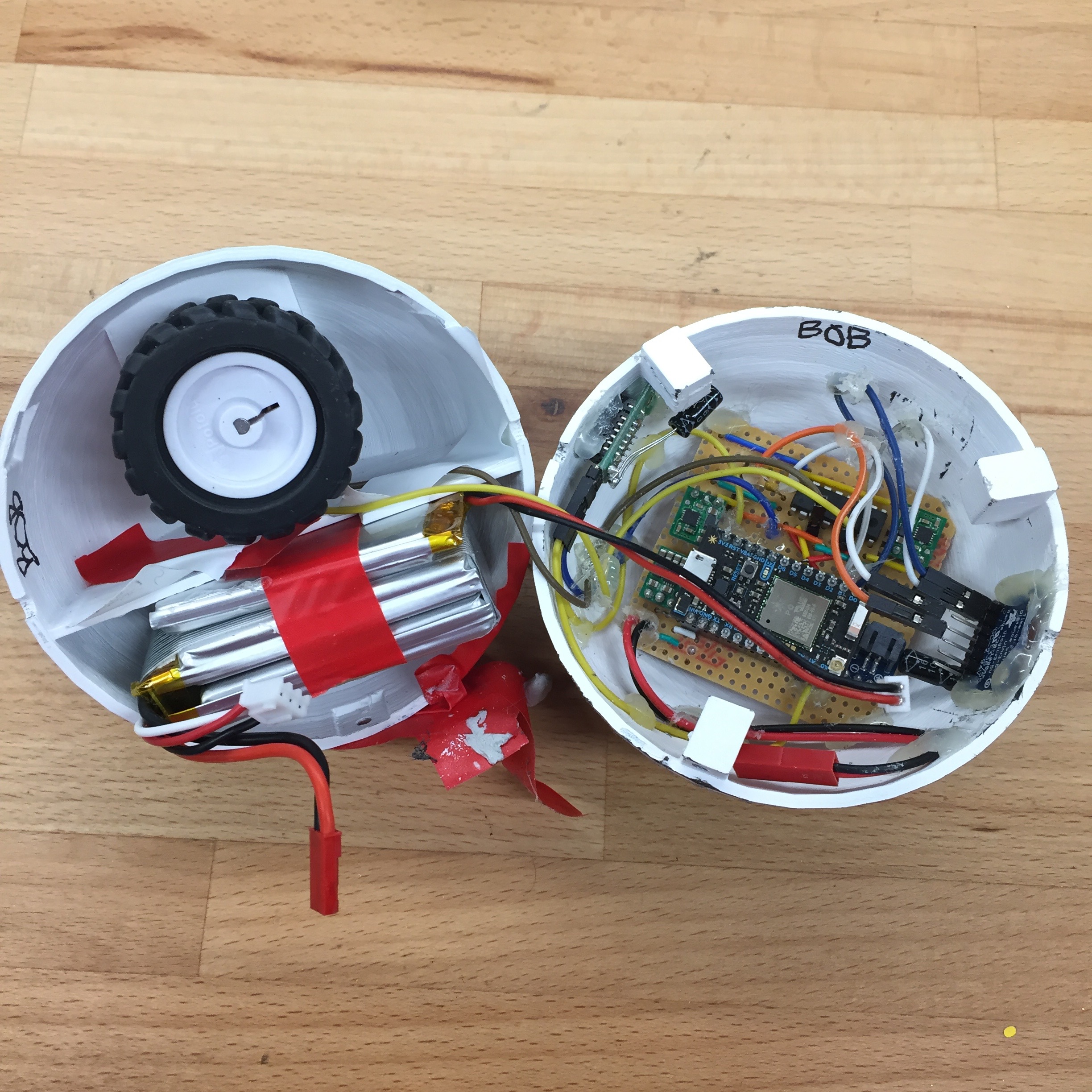
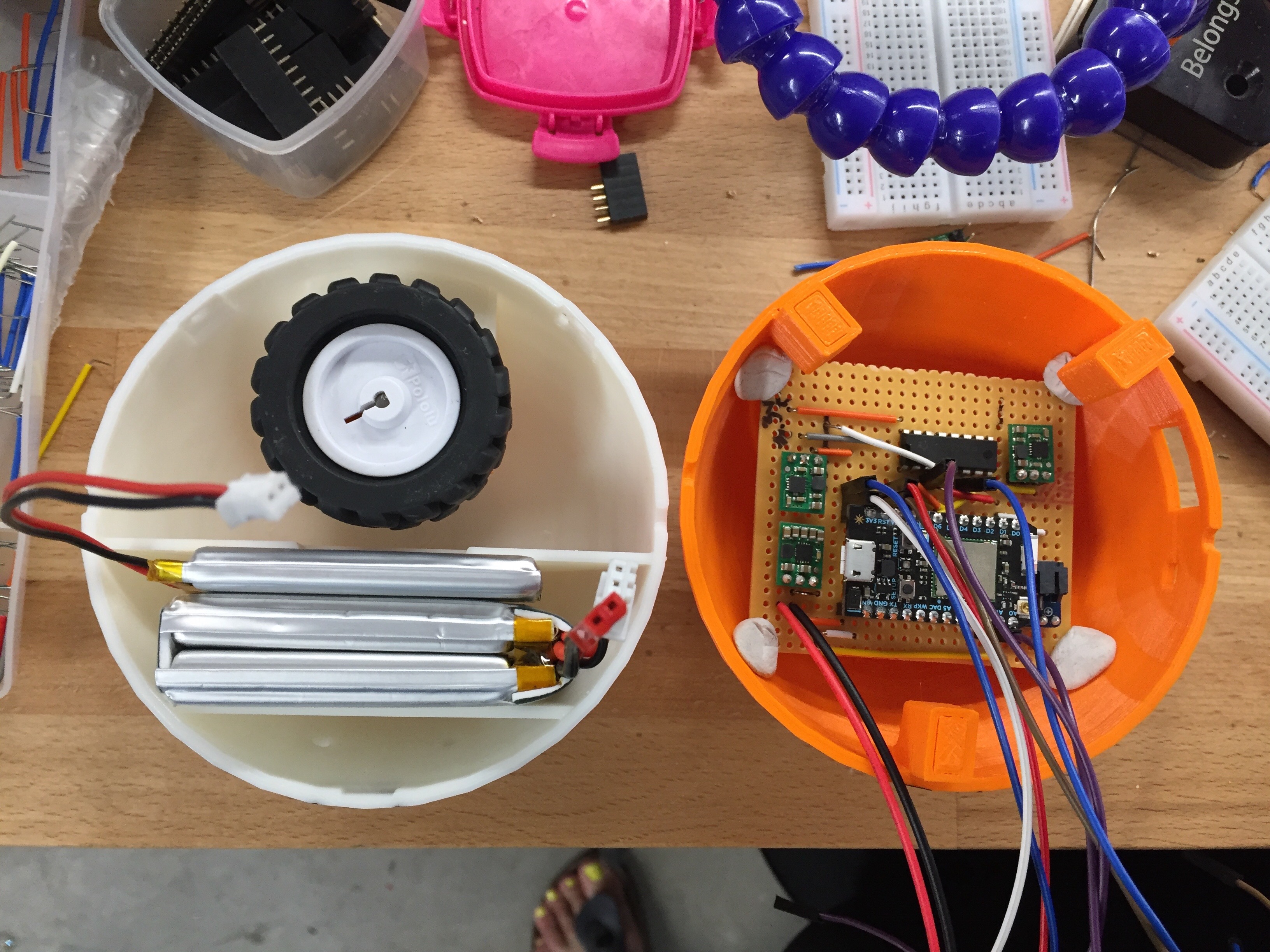
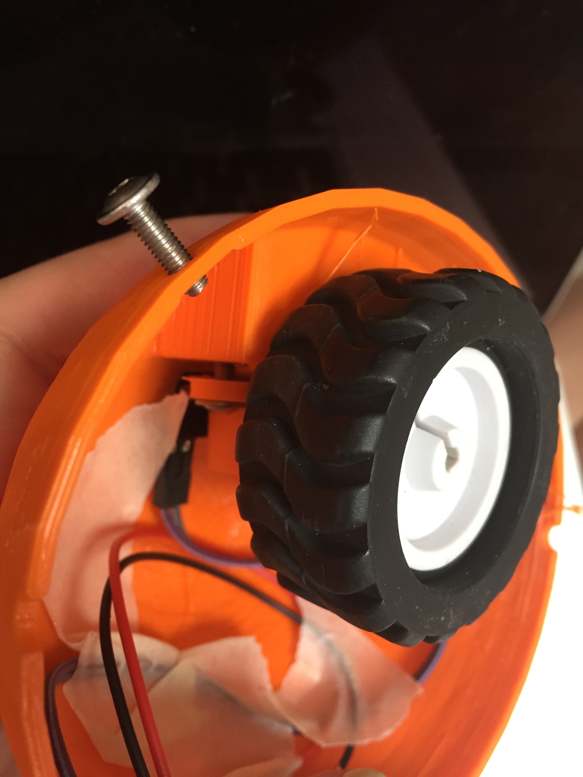
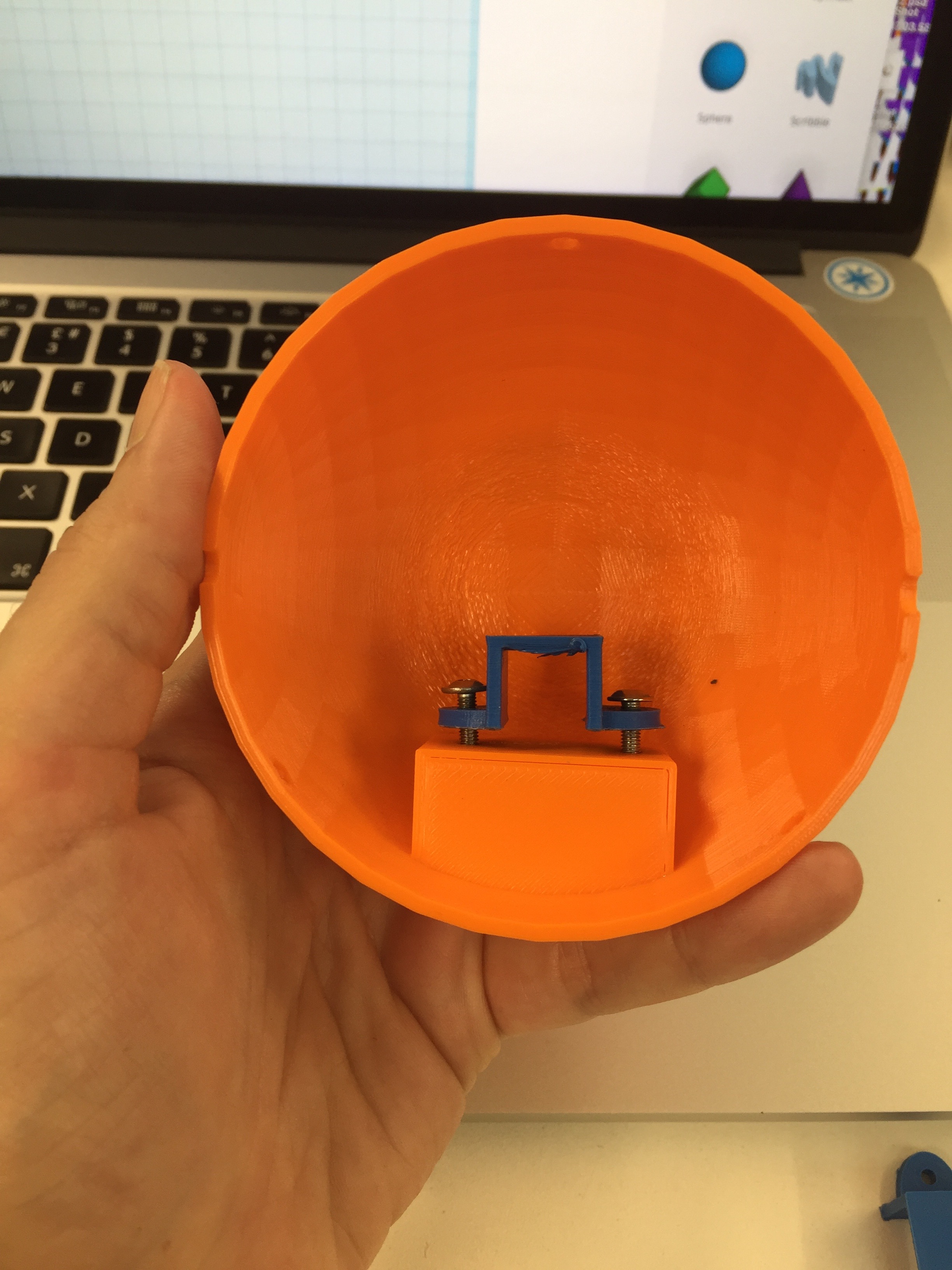
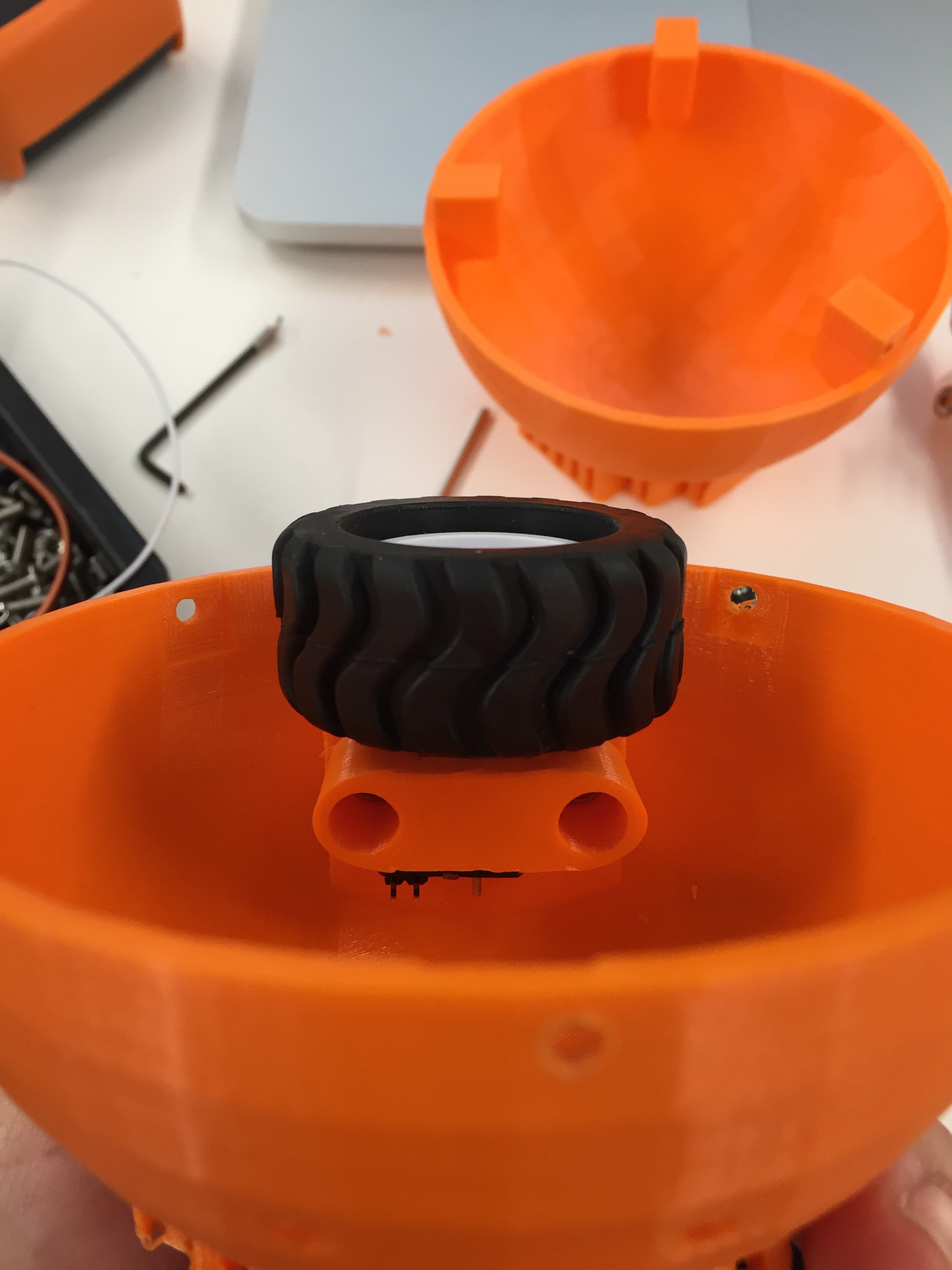
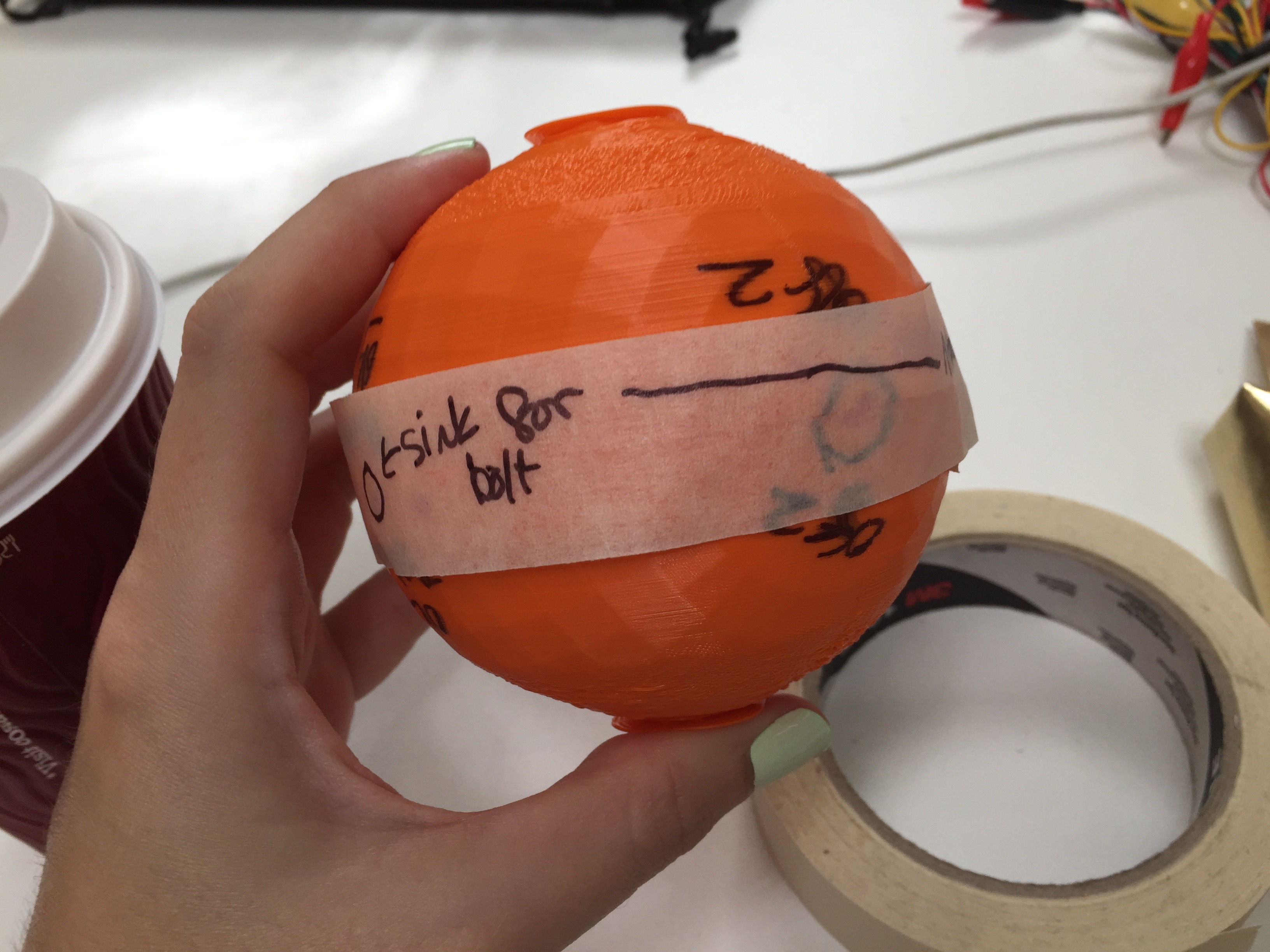
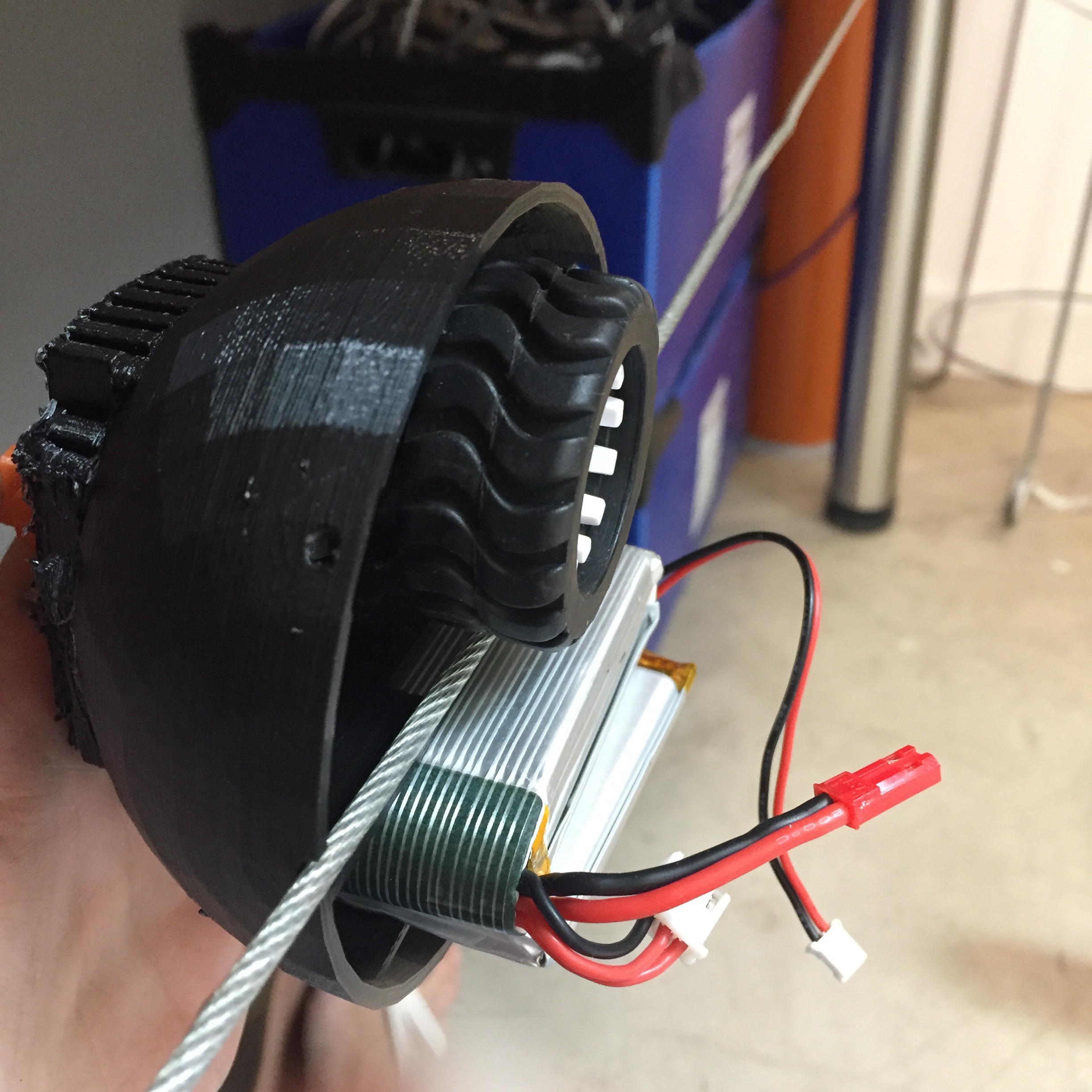
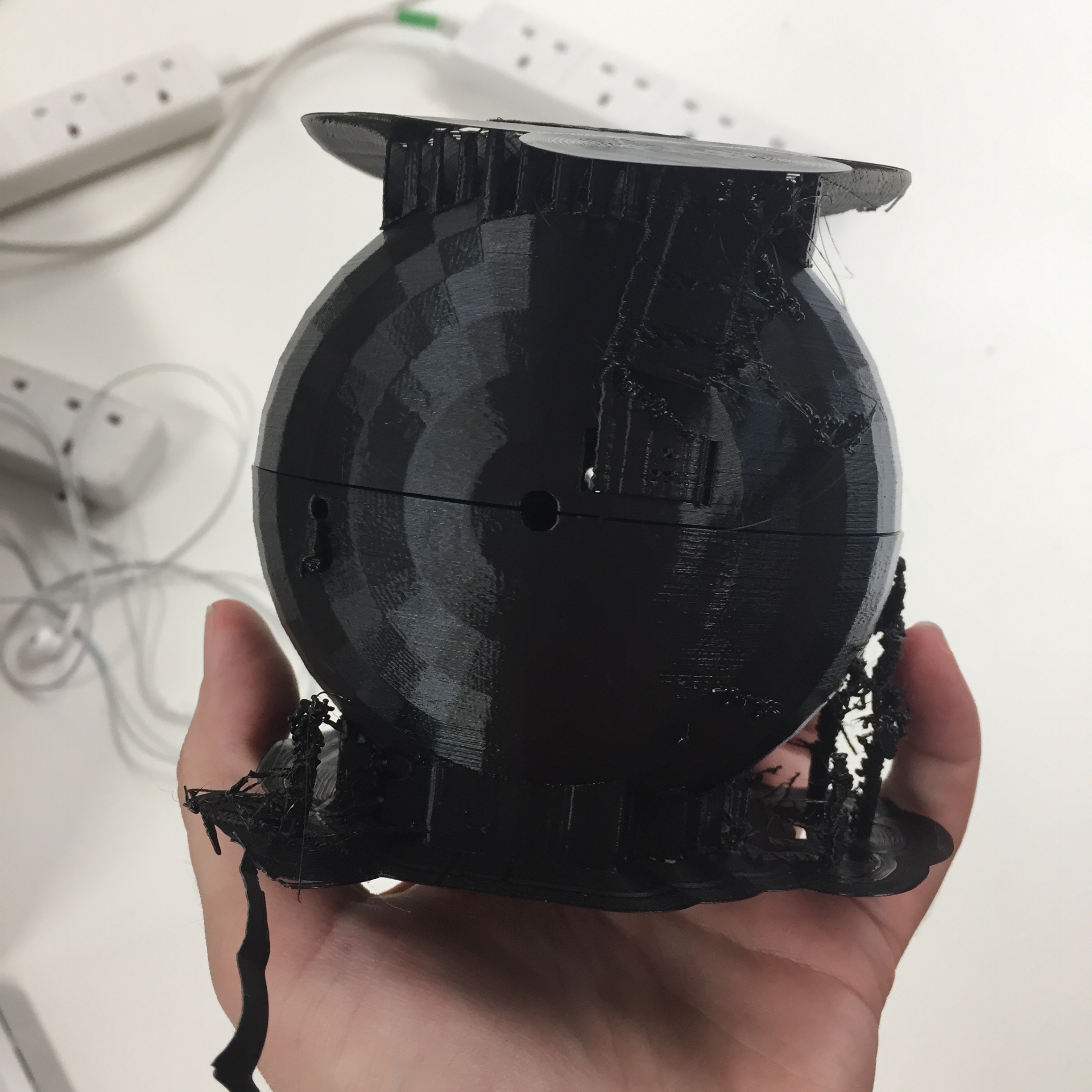
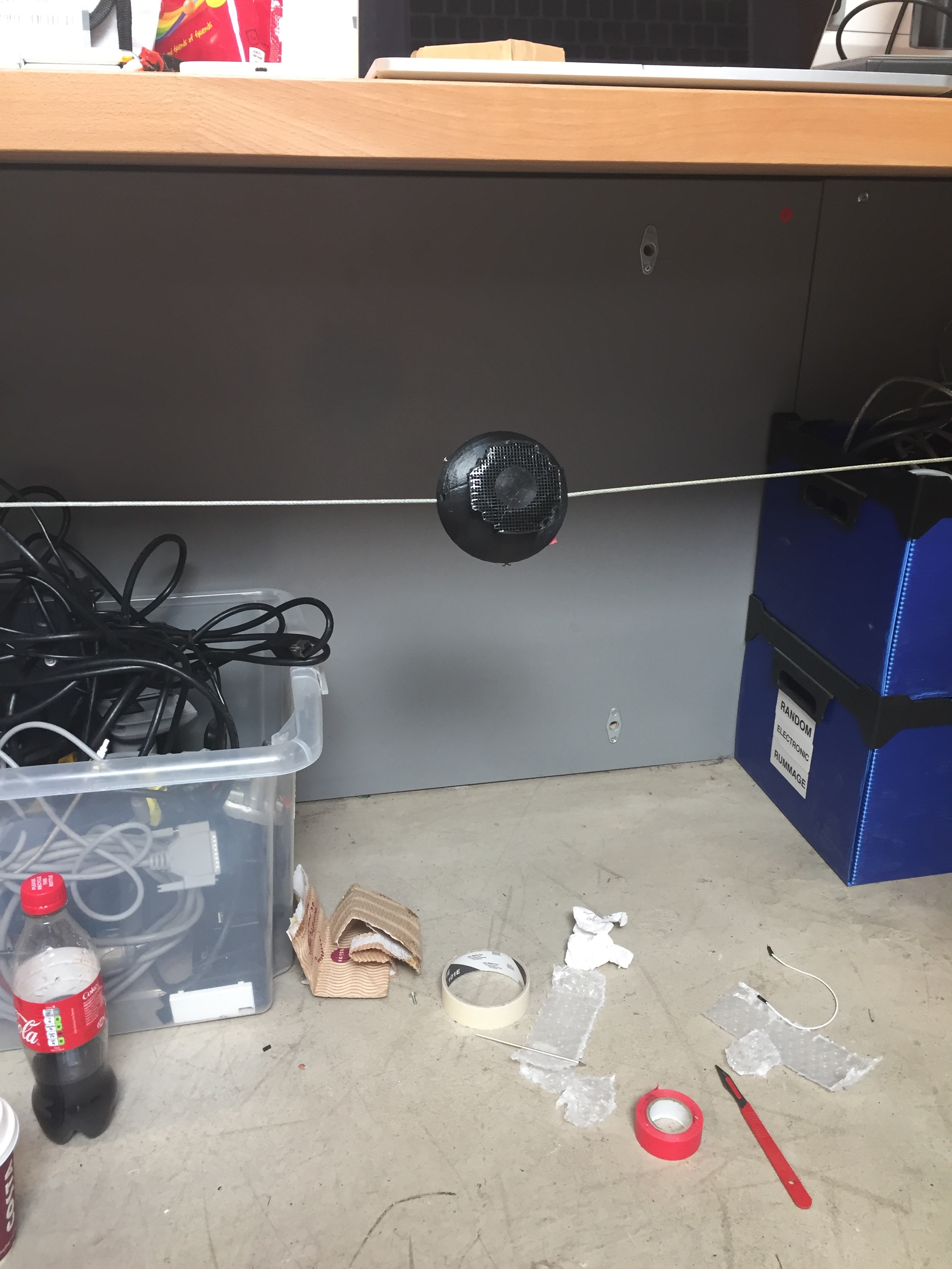
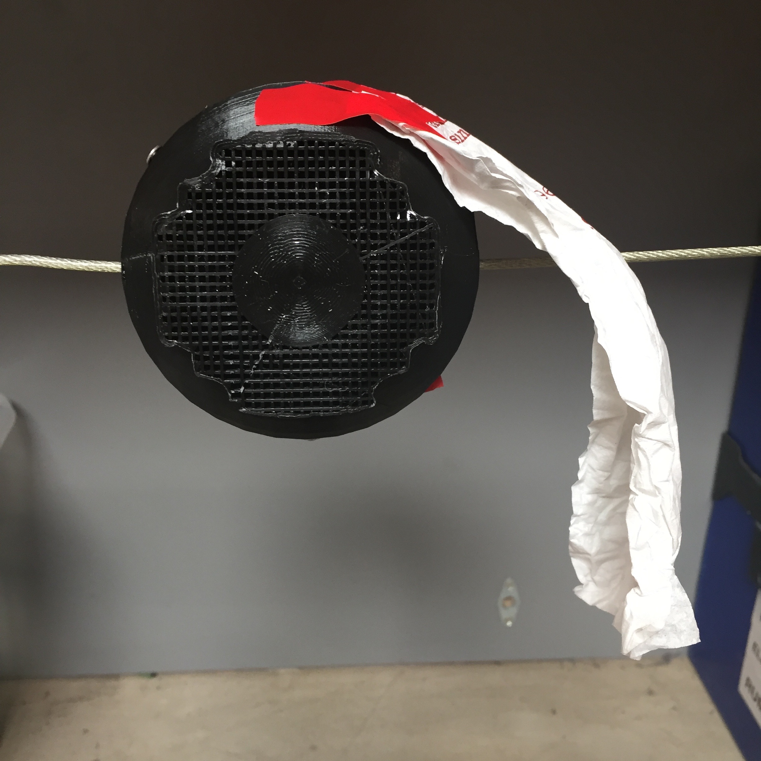
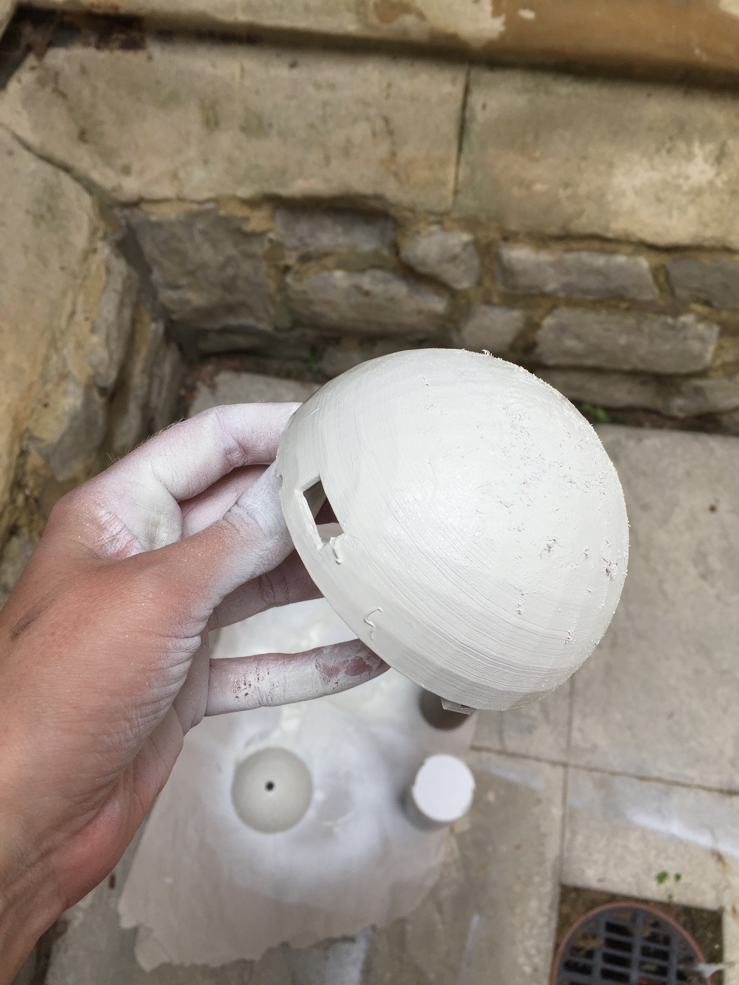
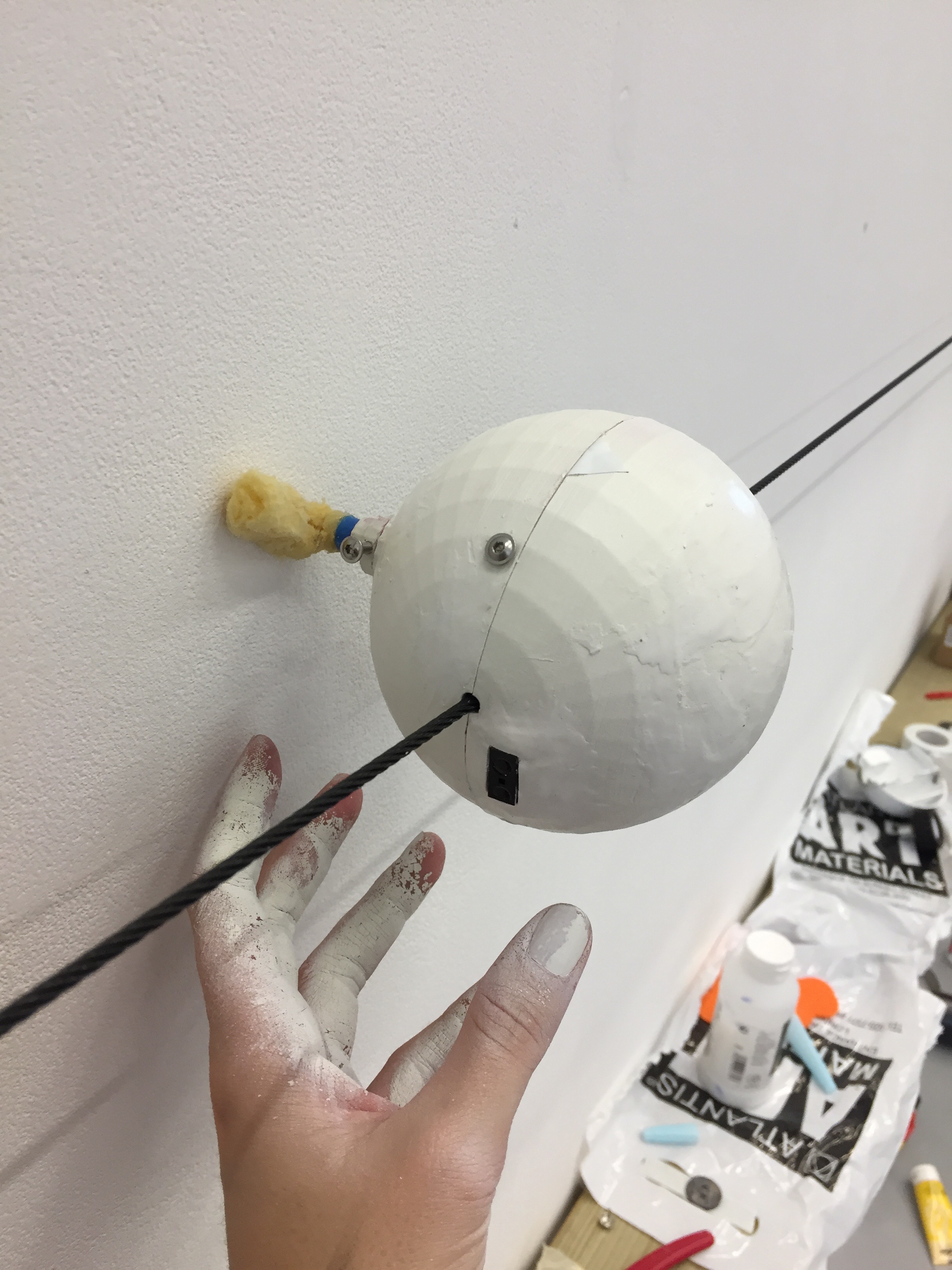
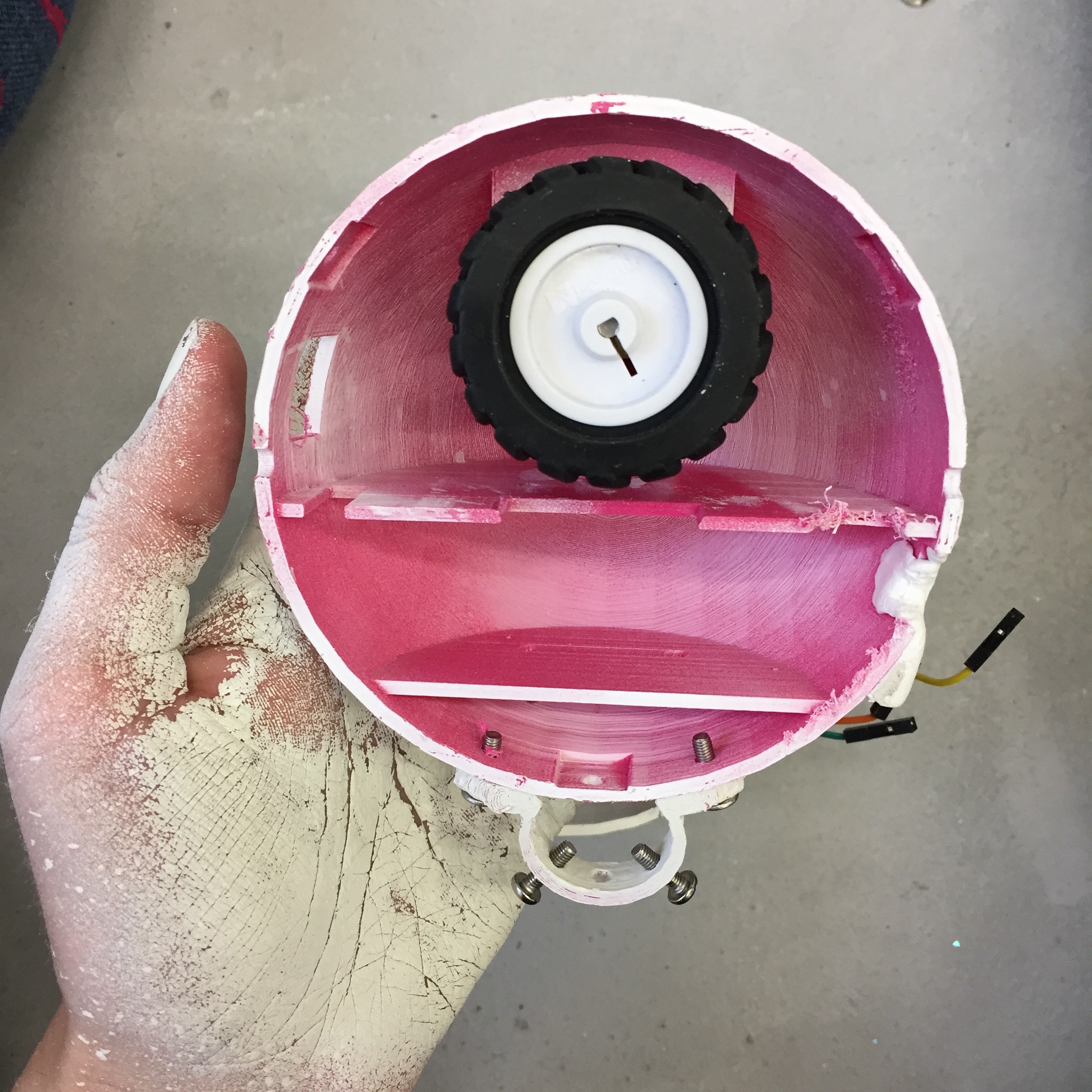
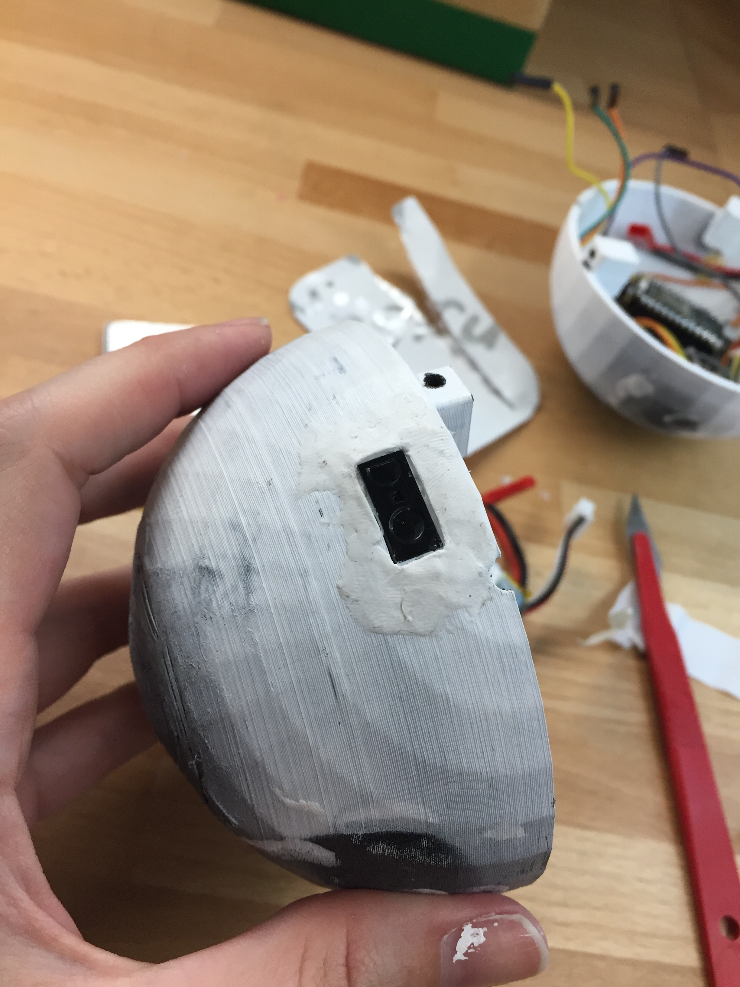
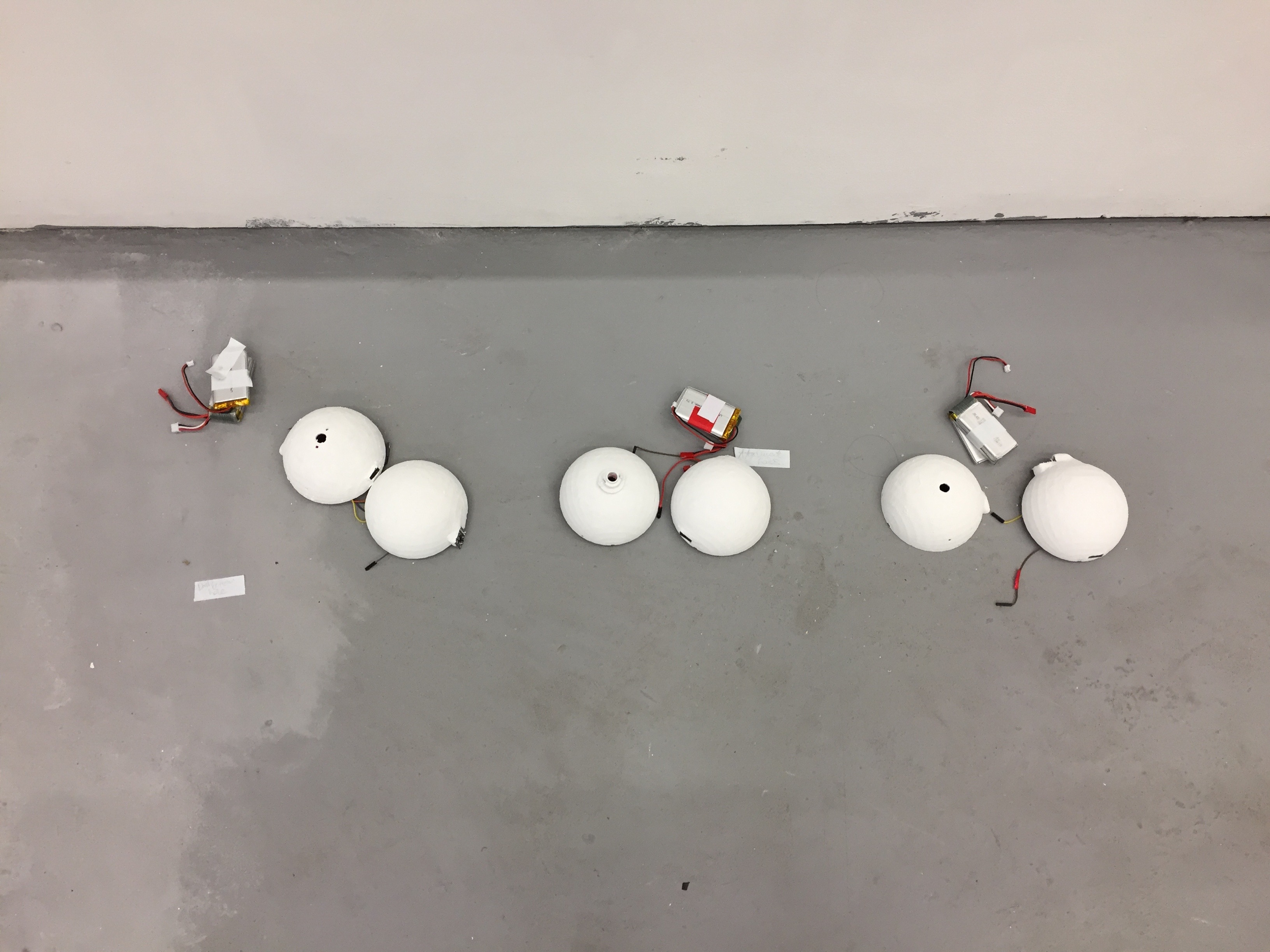
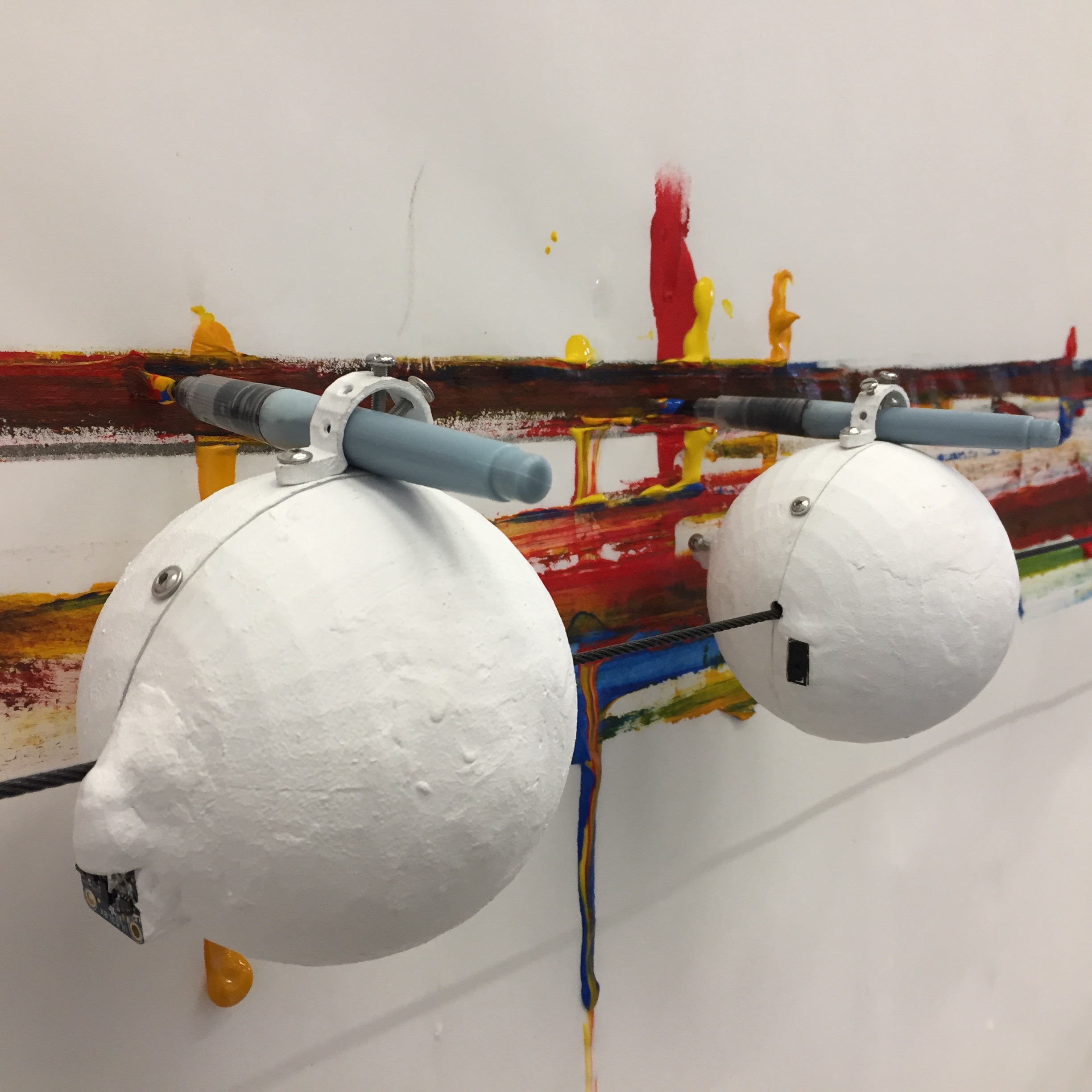
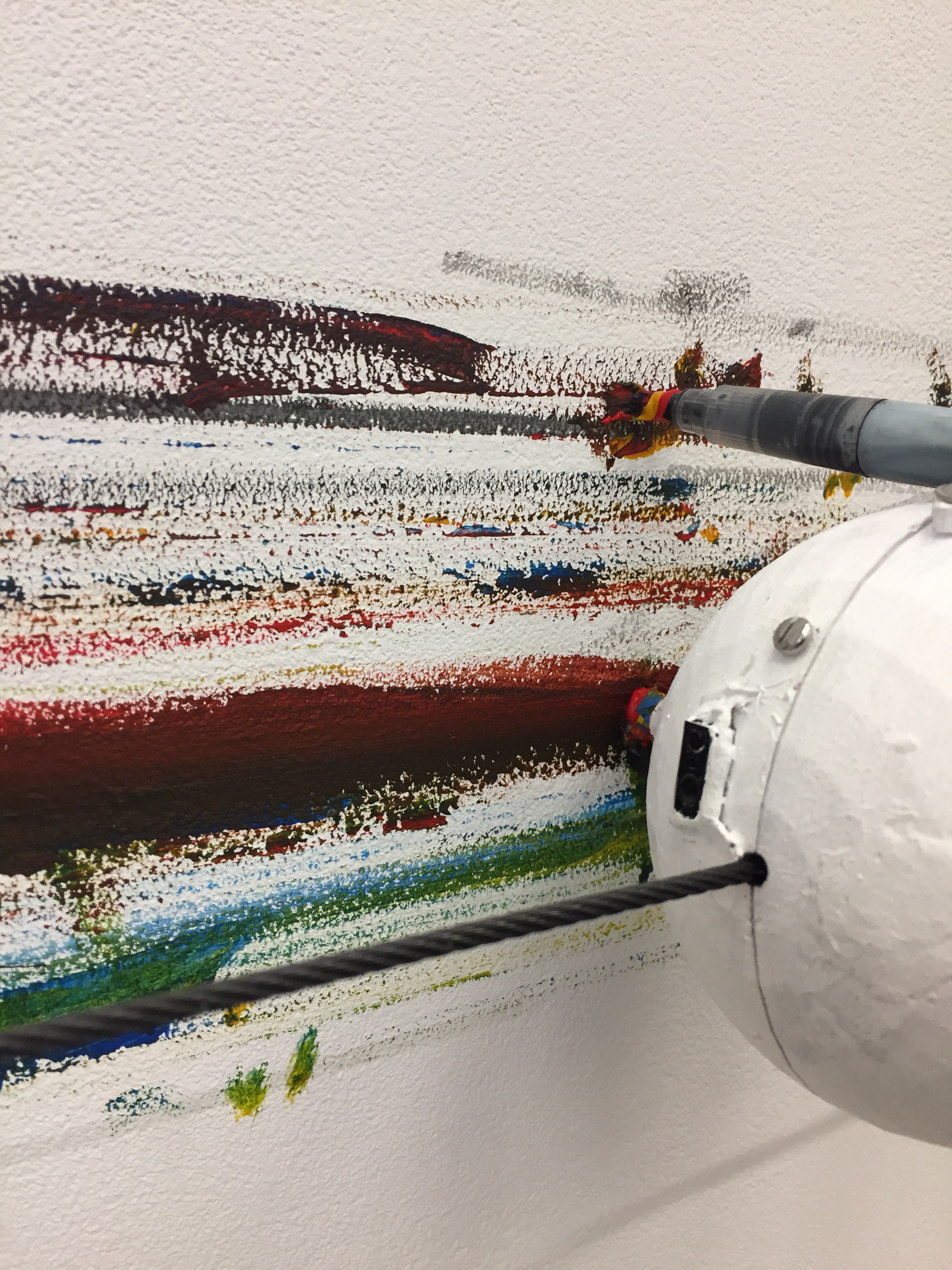
From my work on the prototype robots, I knew that any separable connection to the body of the robot was a weak point. As such, the shell was 3D printed to keep the form as whole as possible for strength, with only the wheel bridge and drawing attachments printed separately. Significant time was spent working on the connections the wheel made with the shell and the wire. An accurate fit between the body of the motor and the form of the robot itself minimised points of pressure and stress on the motor and avoided gears warping over time. In addition, the fit between the wheel and the wire itself was important to ensure good grip without straining and stalling the motor through pressure.
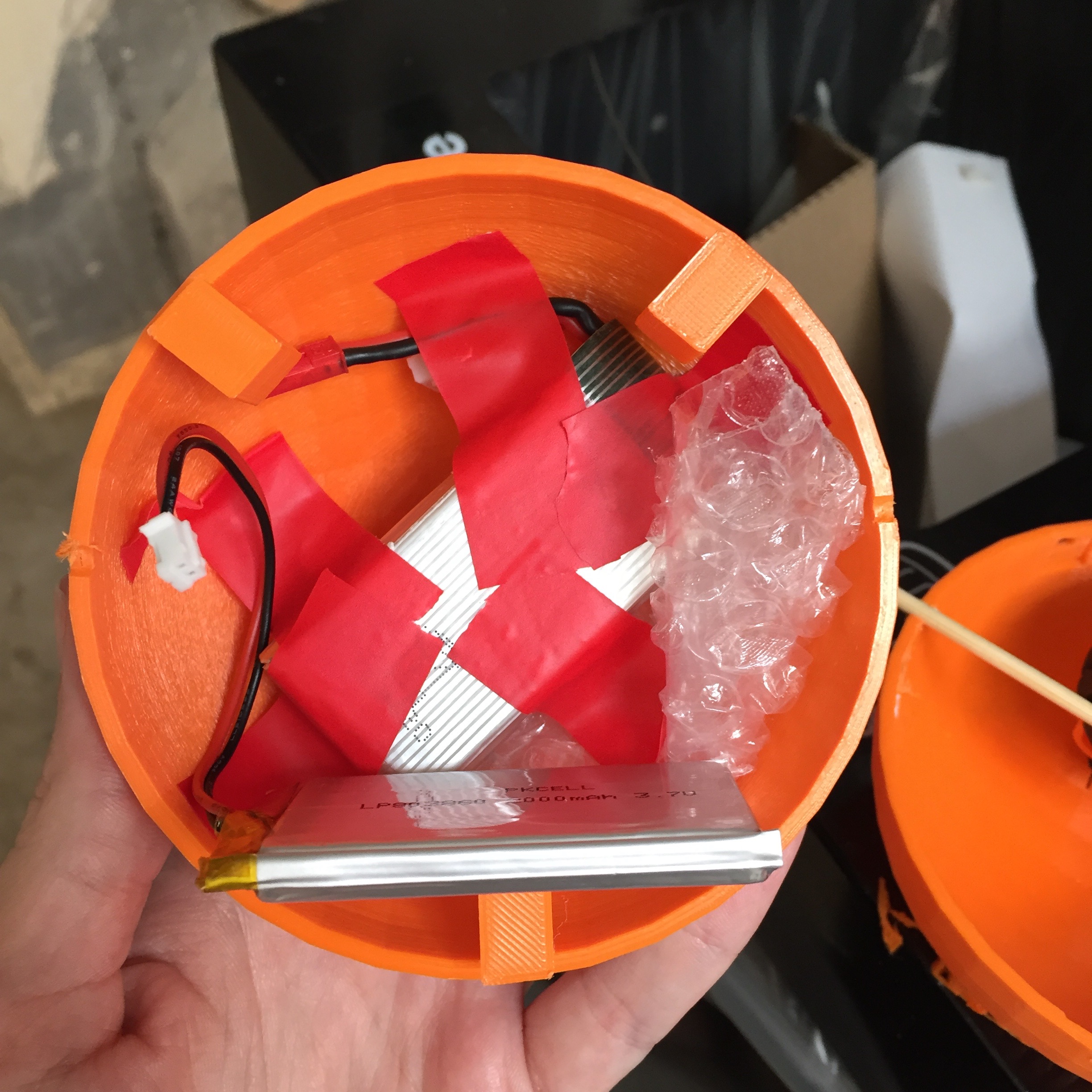
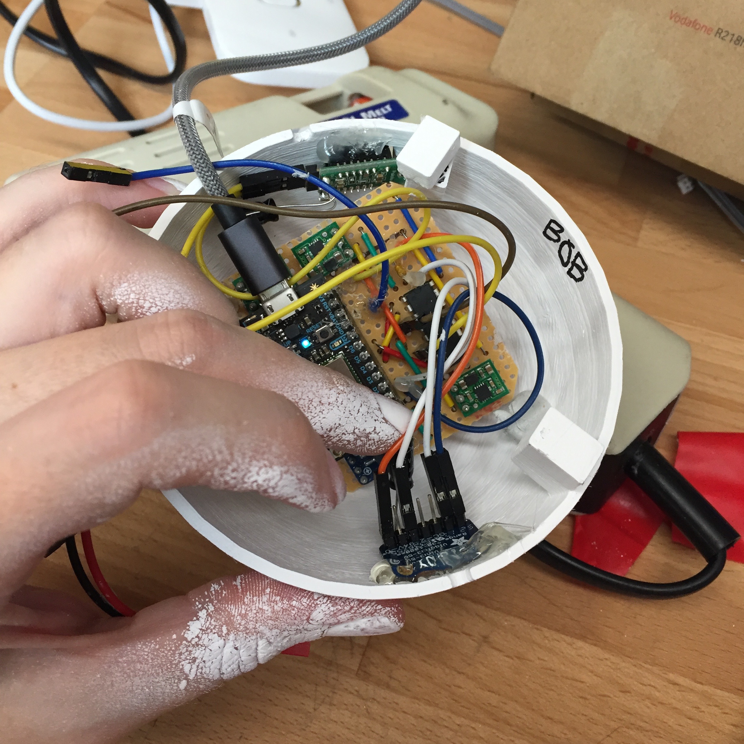
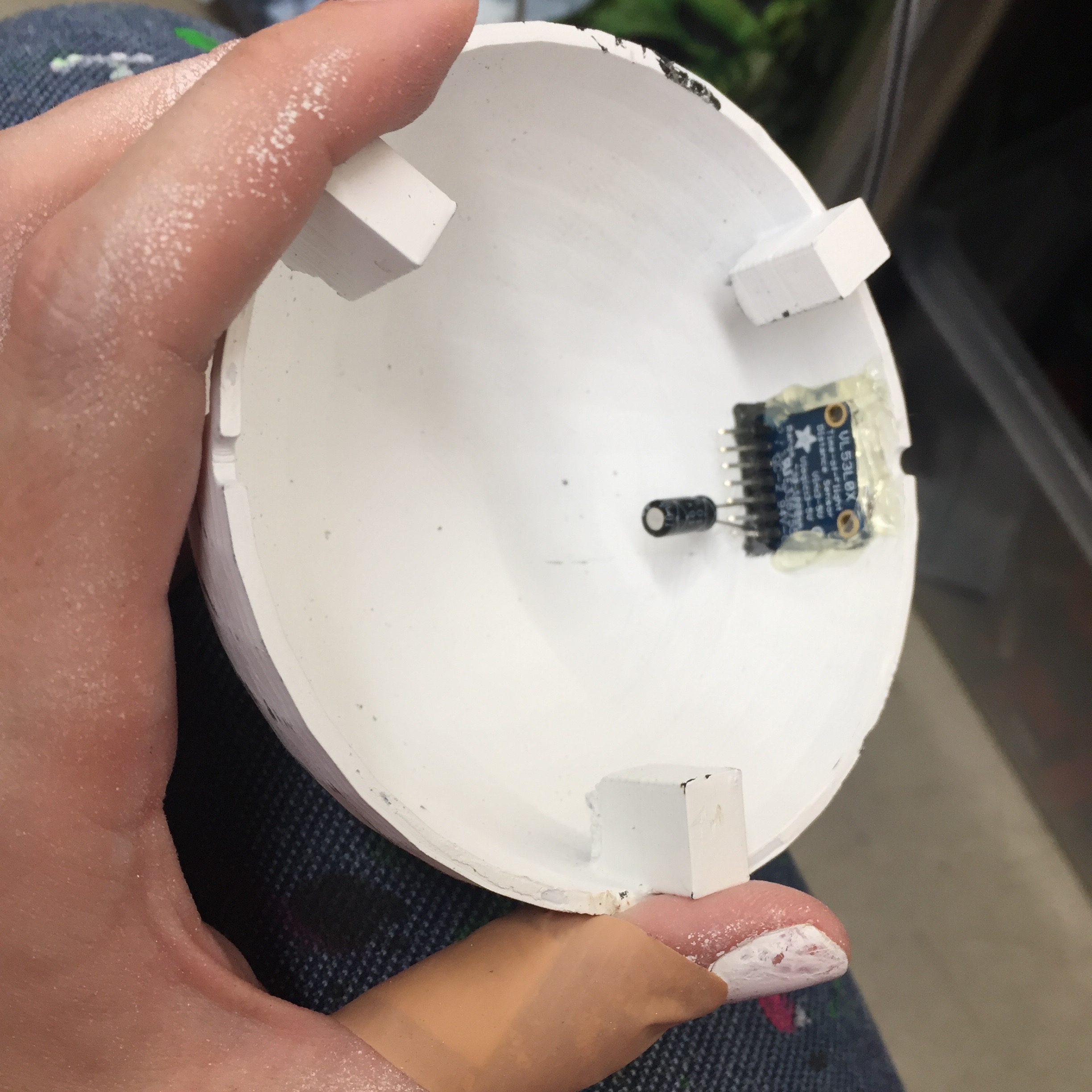
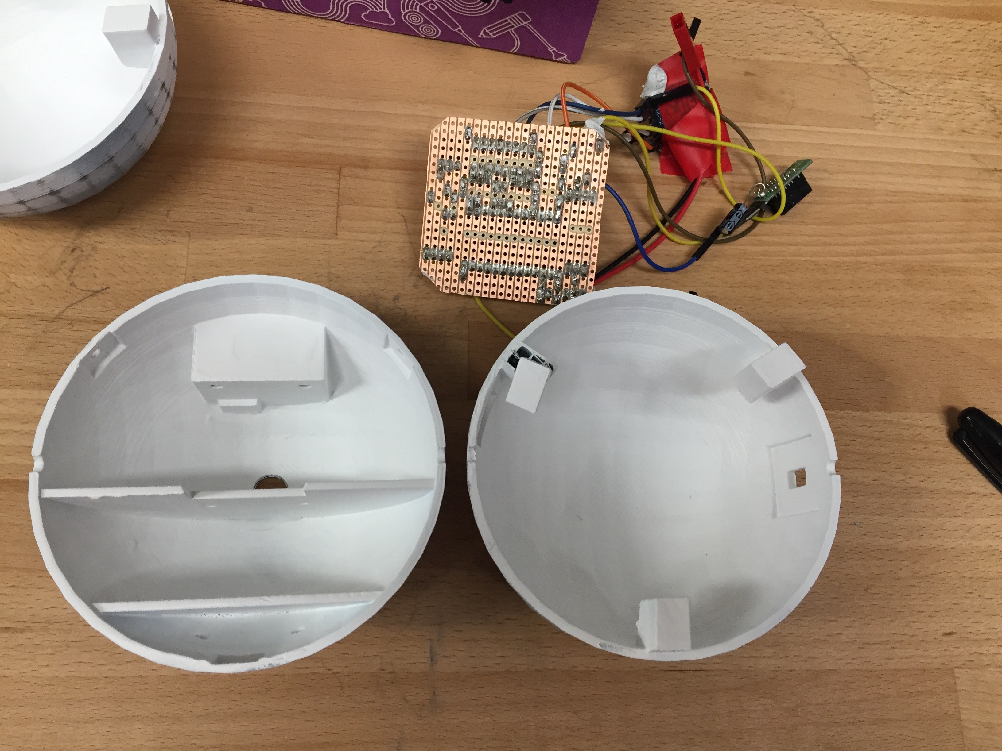
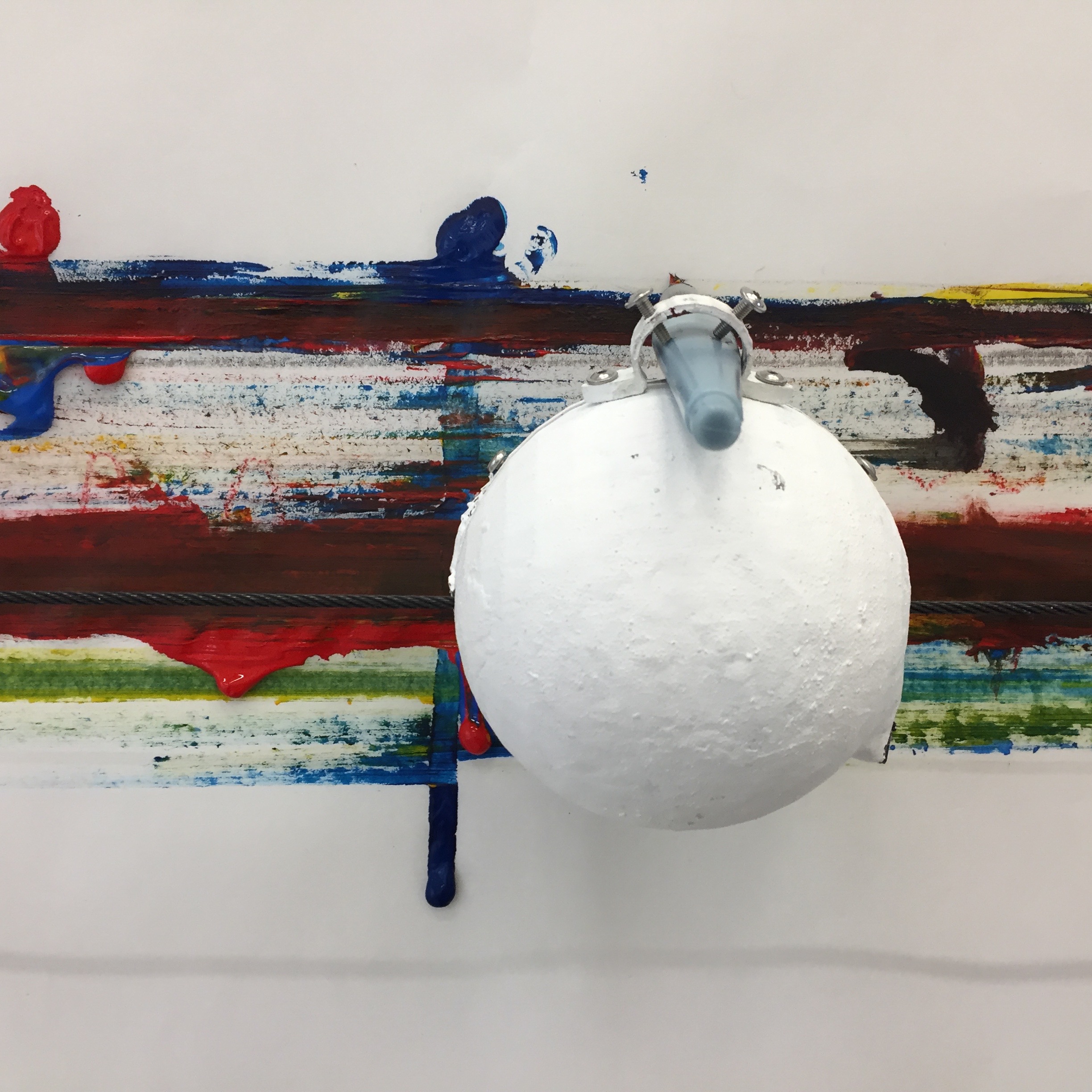
The compact size of the shell (10cm in diameter), its spherical shape, and the weight and size of the batteries was another significant factor in the design of the shell. The batteries needed to be fixed in place to prevent roll, as such shelves were used and the weight of the batteries were used to steady the DrawBots by placing them at the bottom of the sphere.
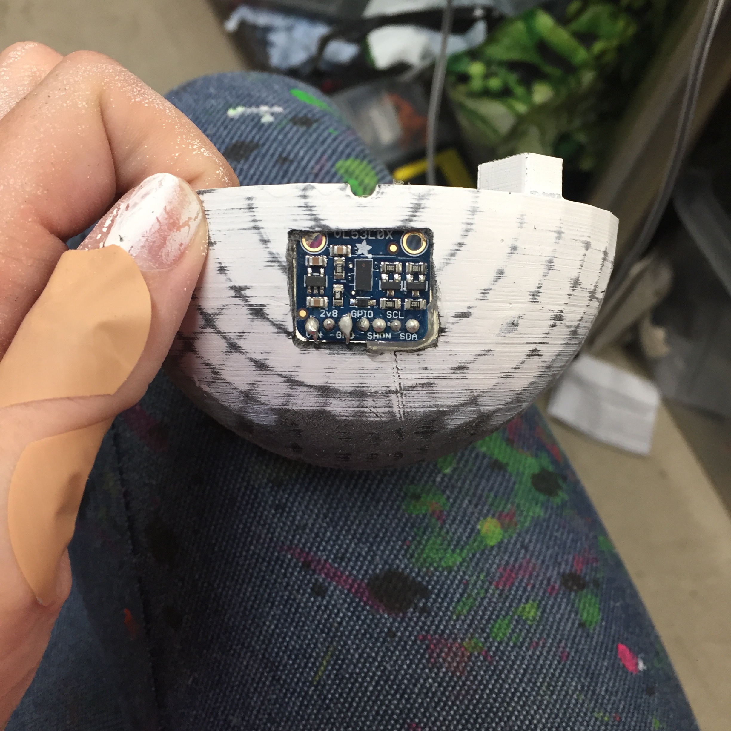
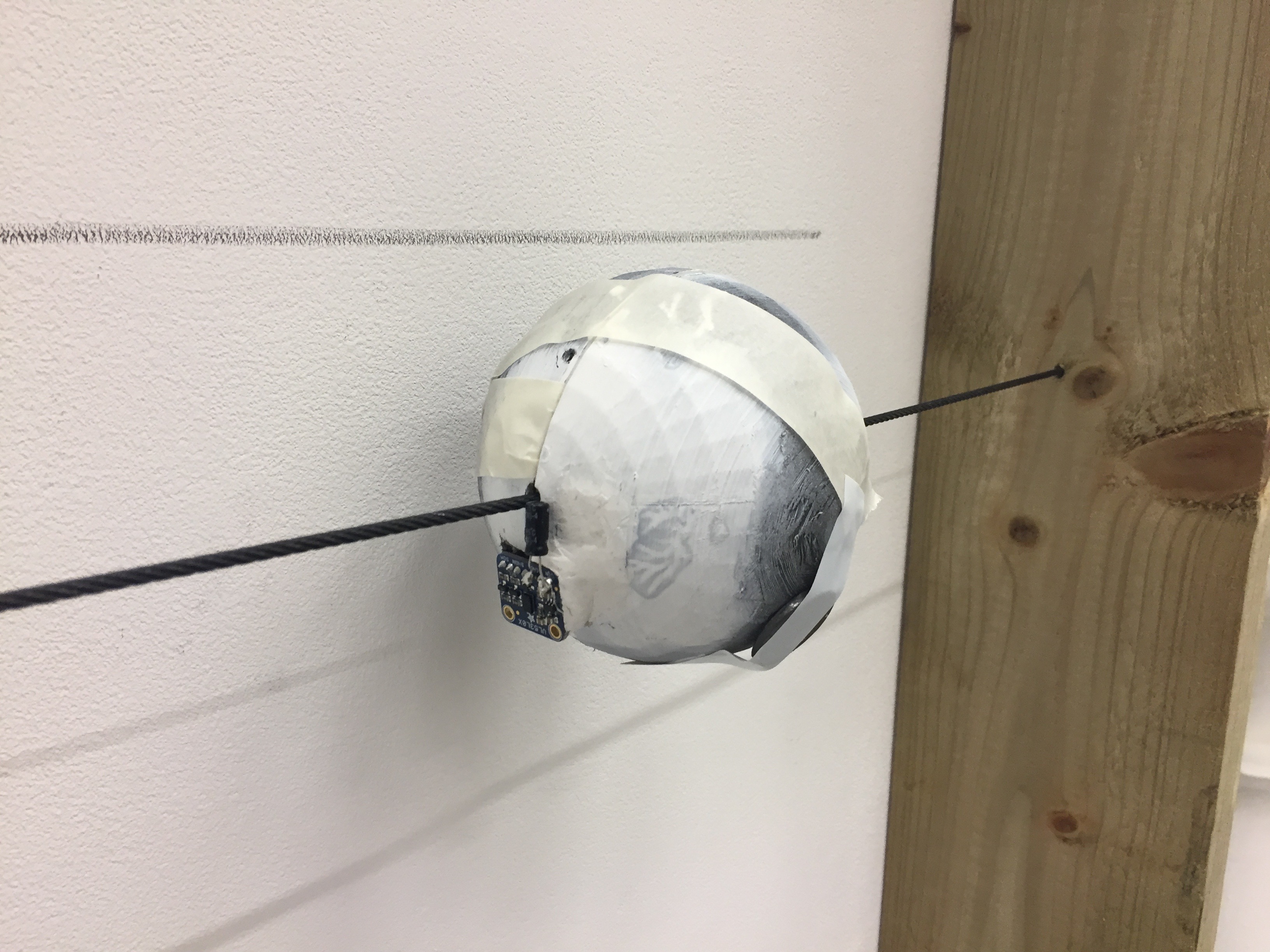
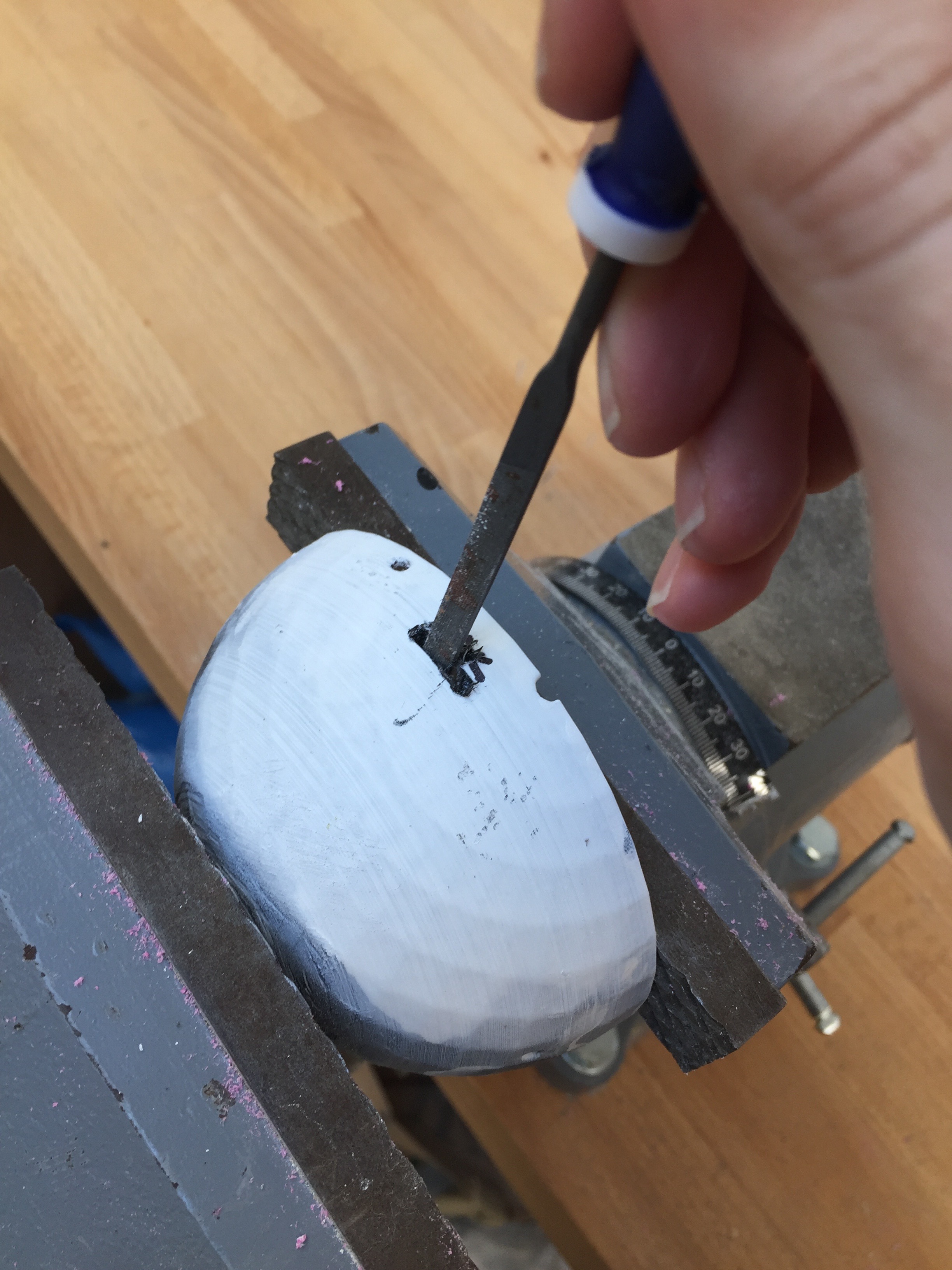
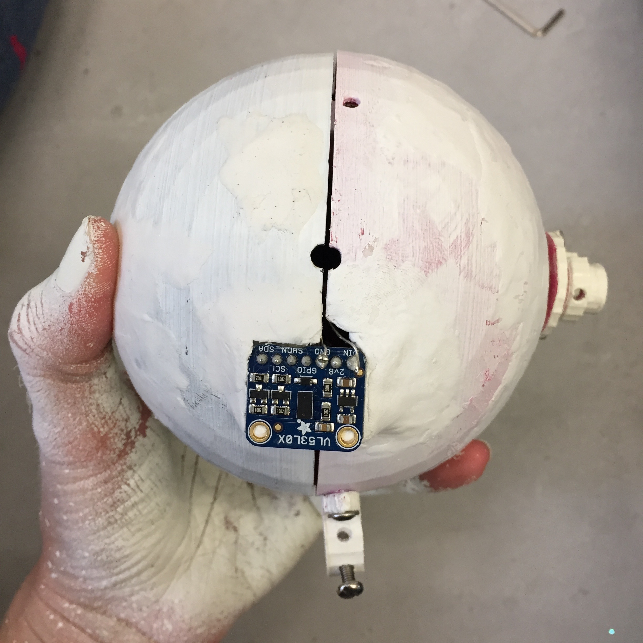
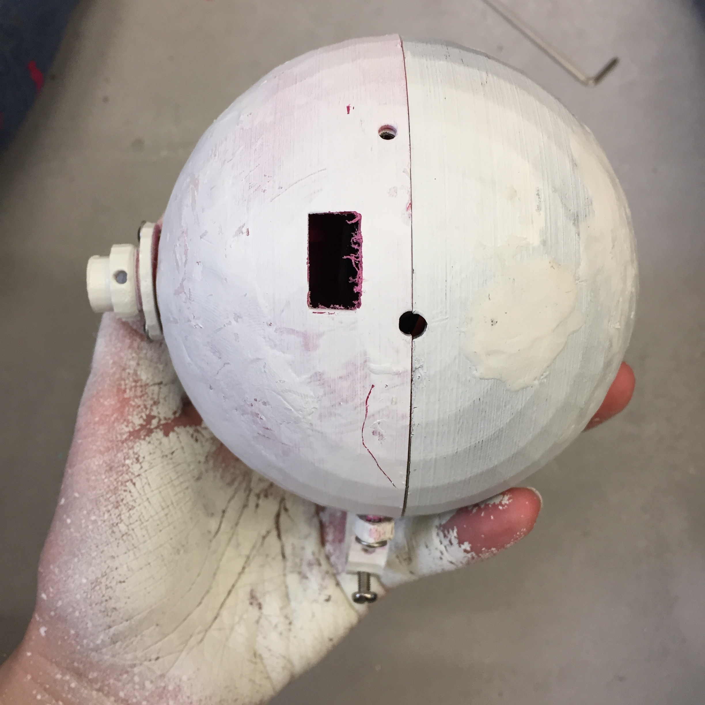
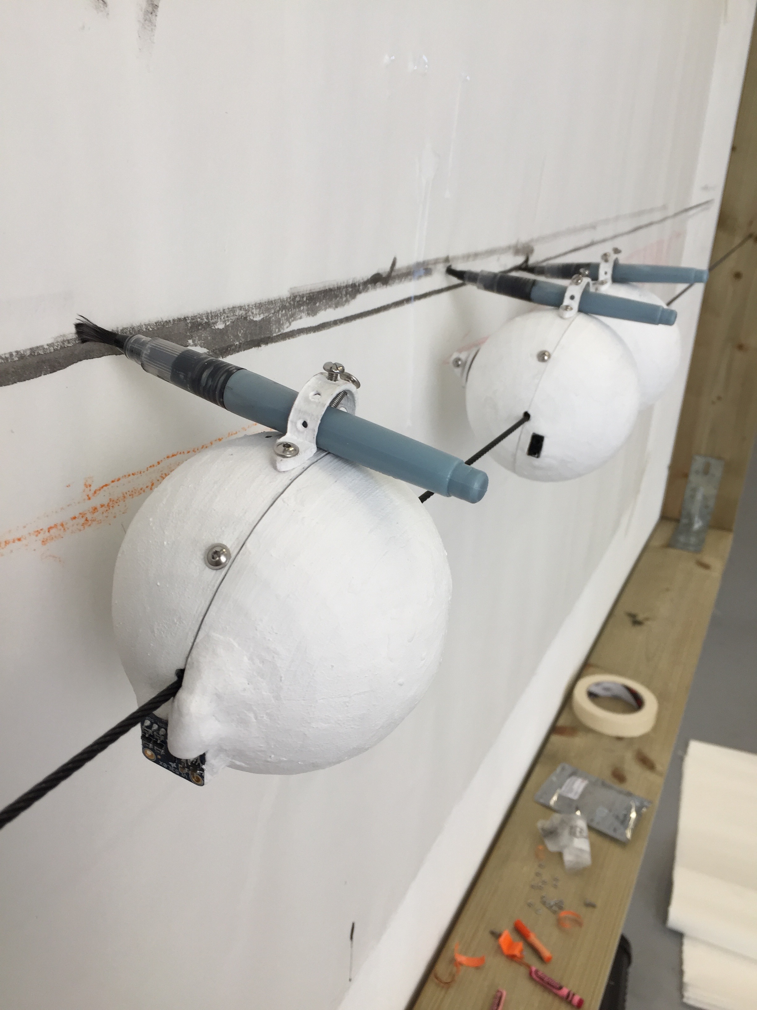
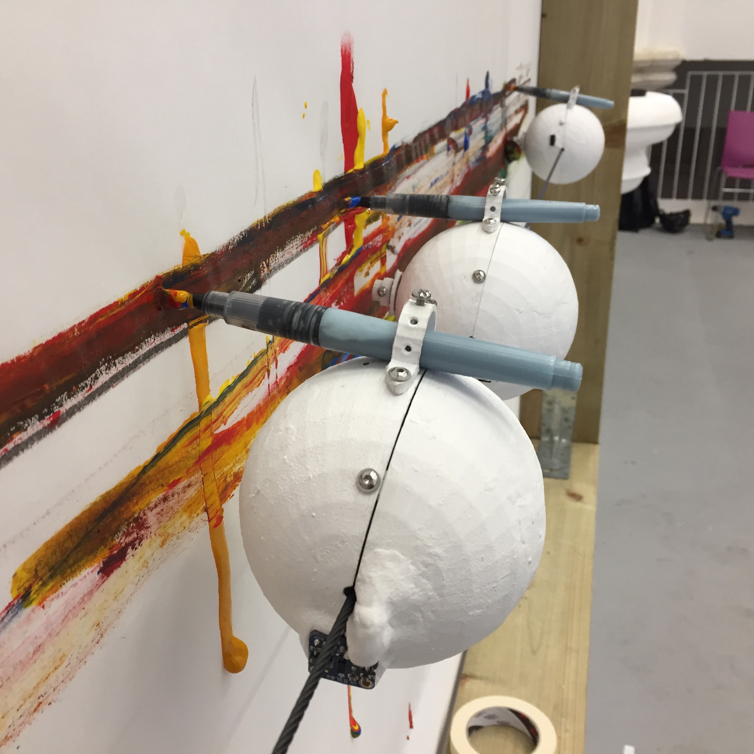
The placement of the sensors in the shell was another technical challenge which required a series of experiments, also including this and this. The IR sensors could not directly face each other to avoid interference from the opposite IR sensor. Initially too, the time of flight sensor was placed as close to the wire as possible to capture measurements from the widest part of the sphere. However, I found that the time of flight sensor would pick up the wire once the robot reached the middle point of the wire presumably due to slight inaccuracies with the angle of the sensor in the DrawBot. As such, this sensor was moved as far away from the wire as possible whilst still detecting the edge of the frame.
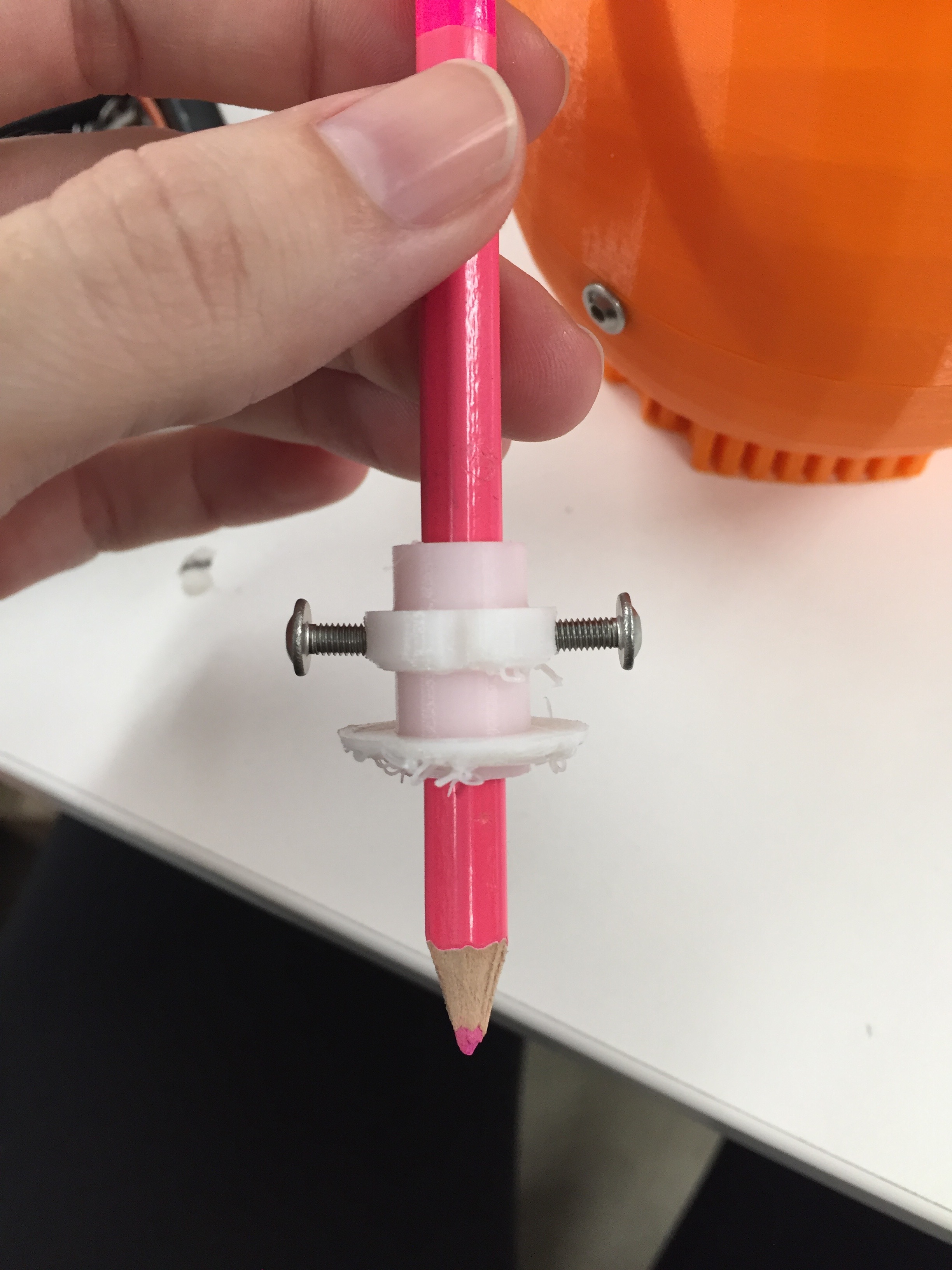
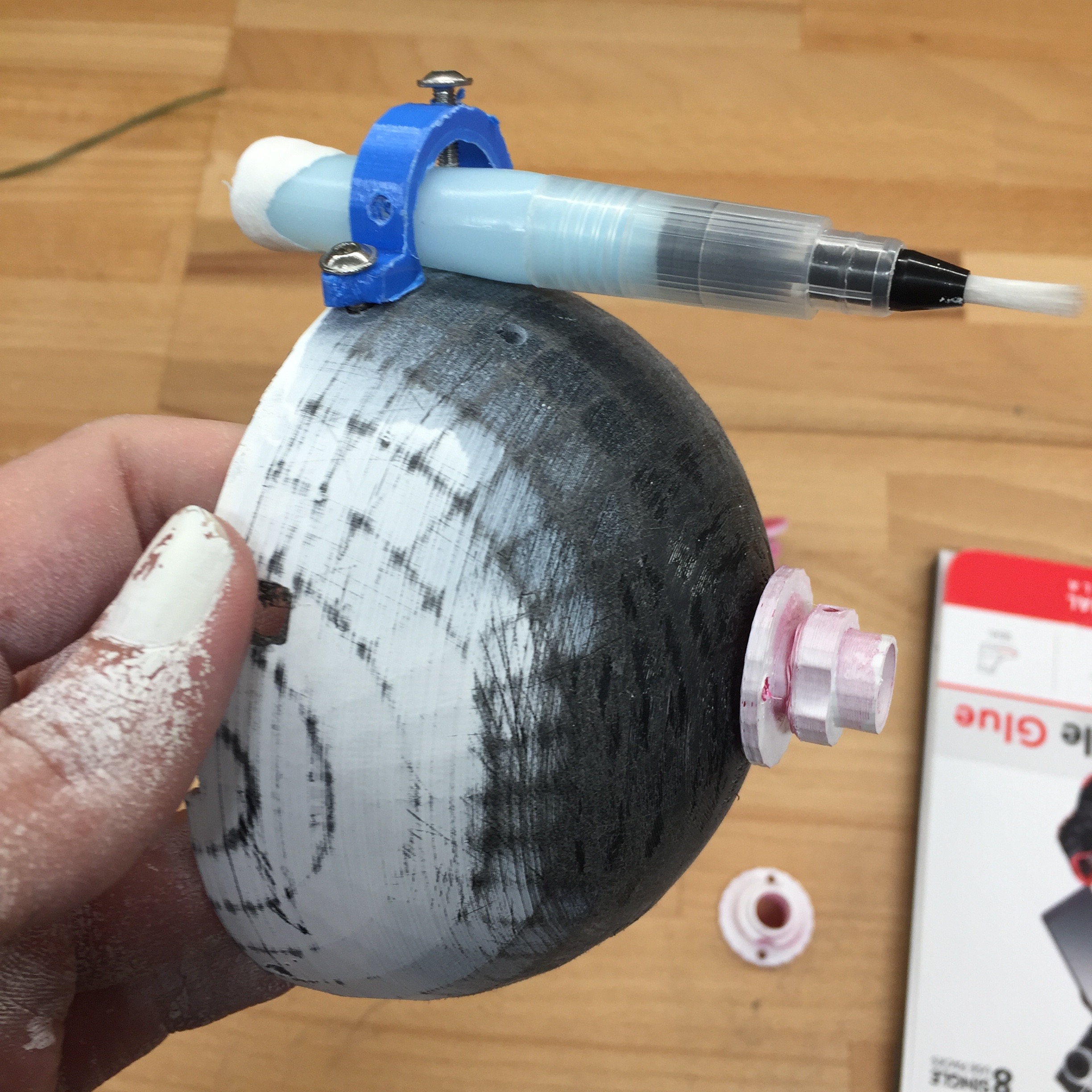
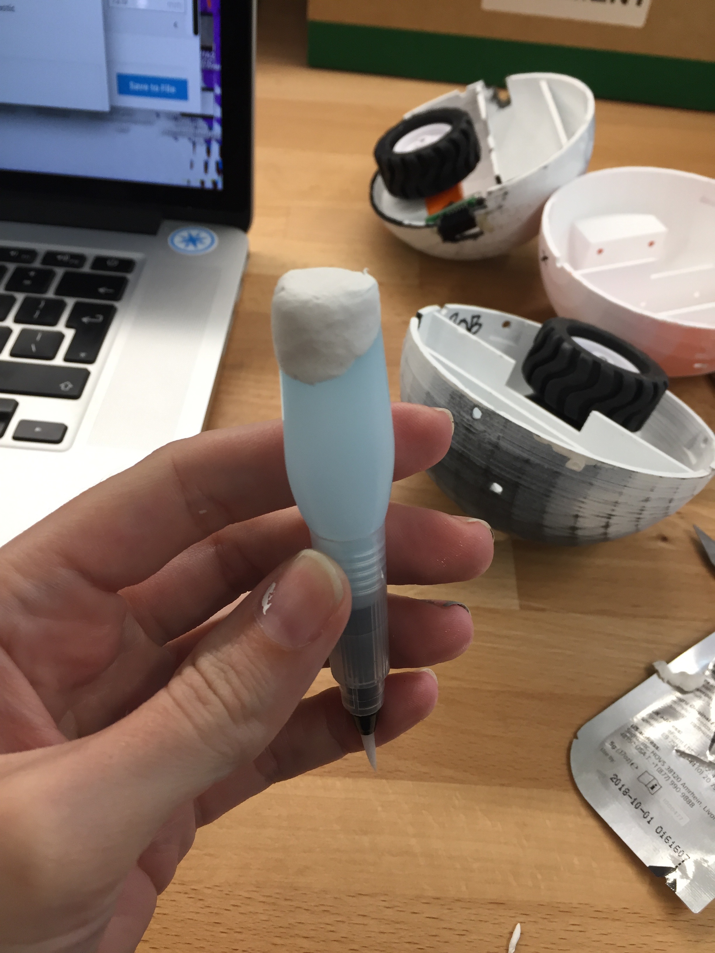
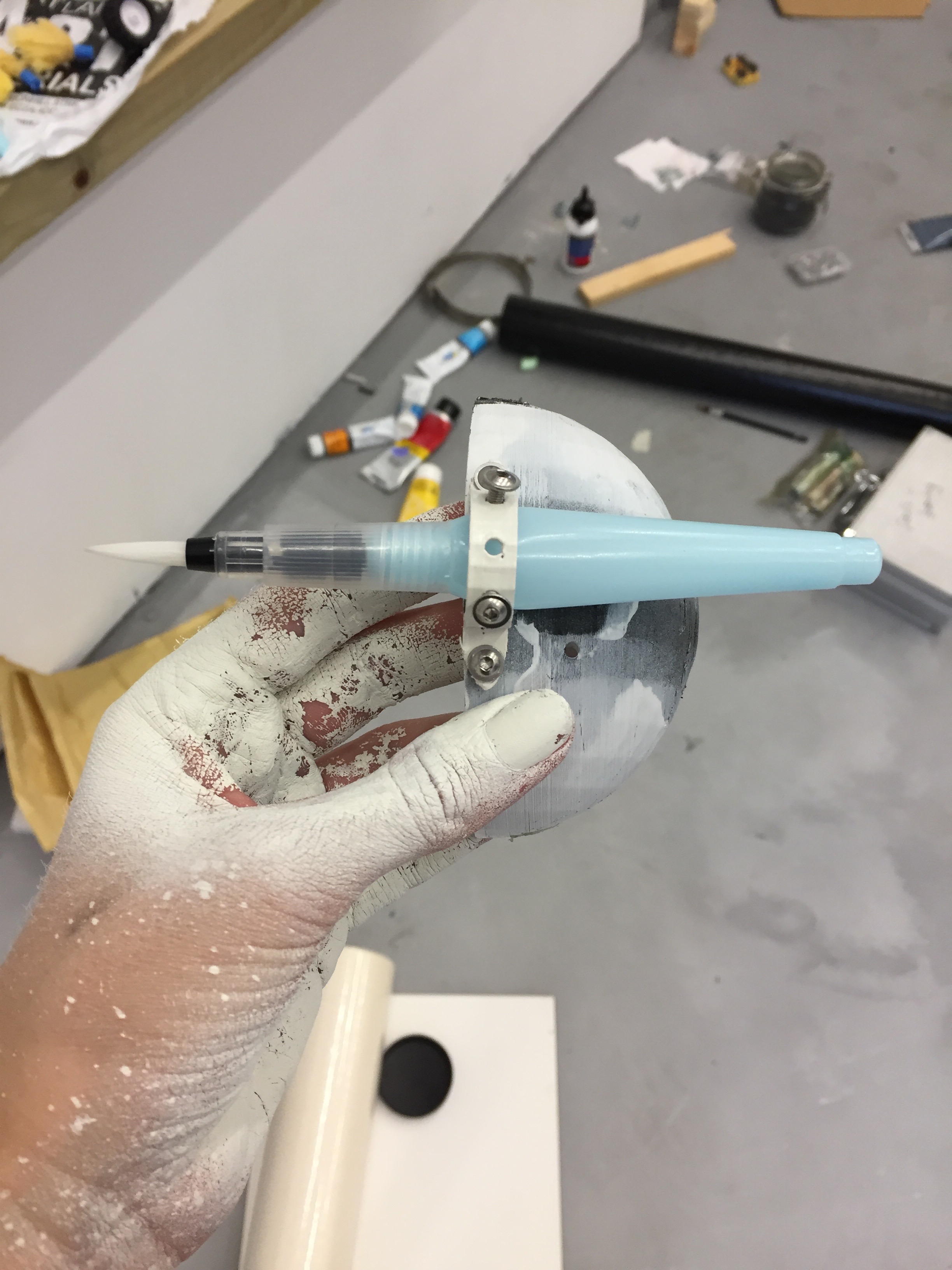
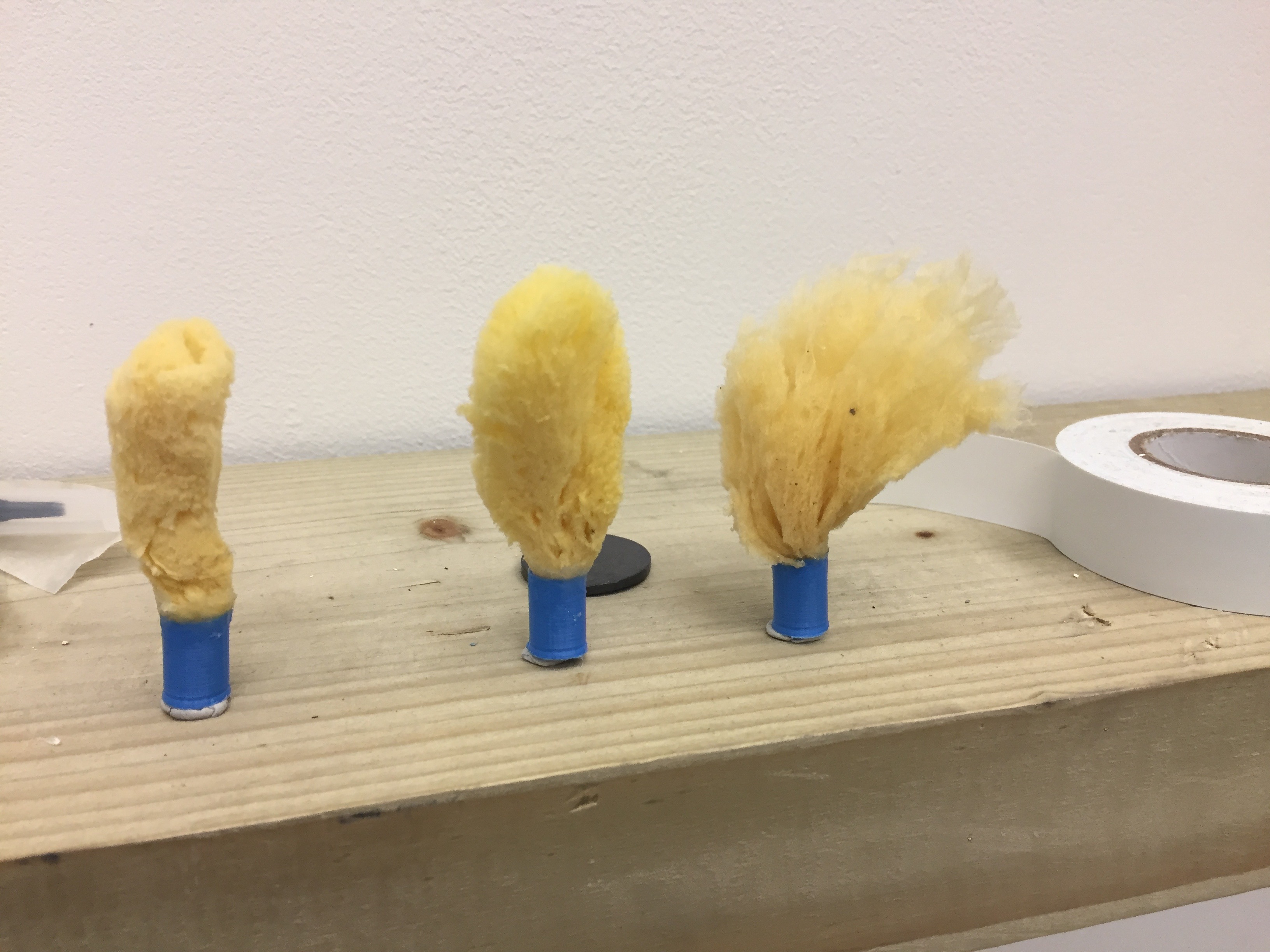
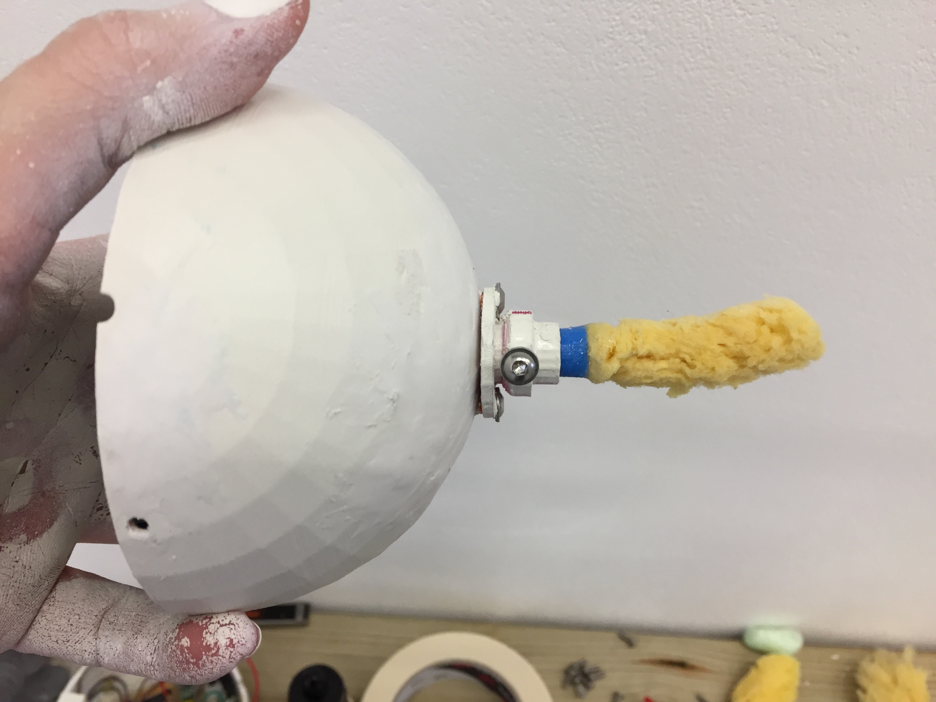
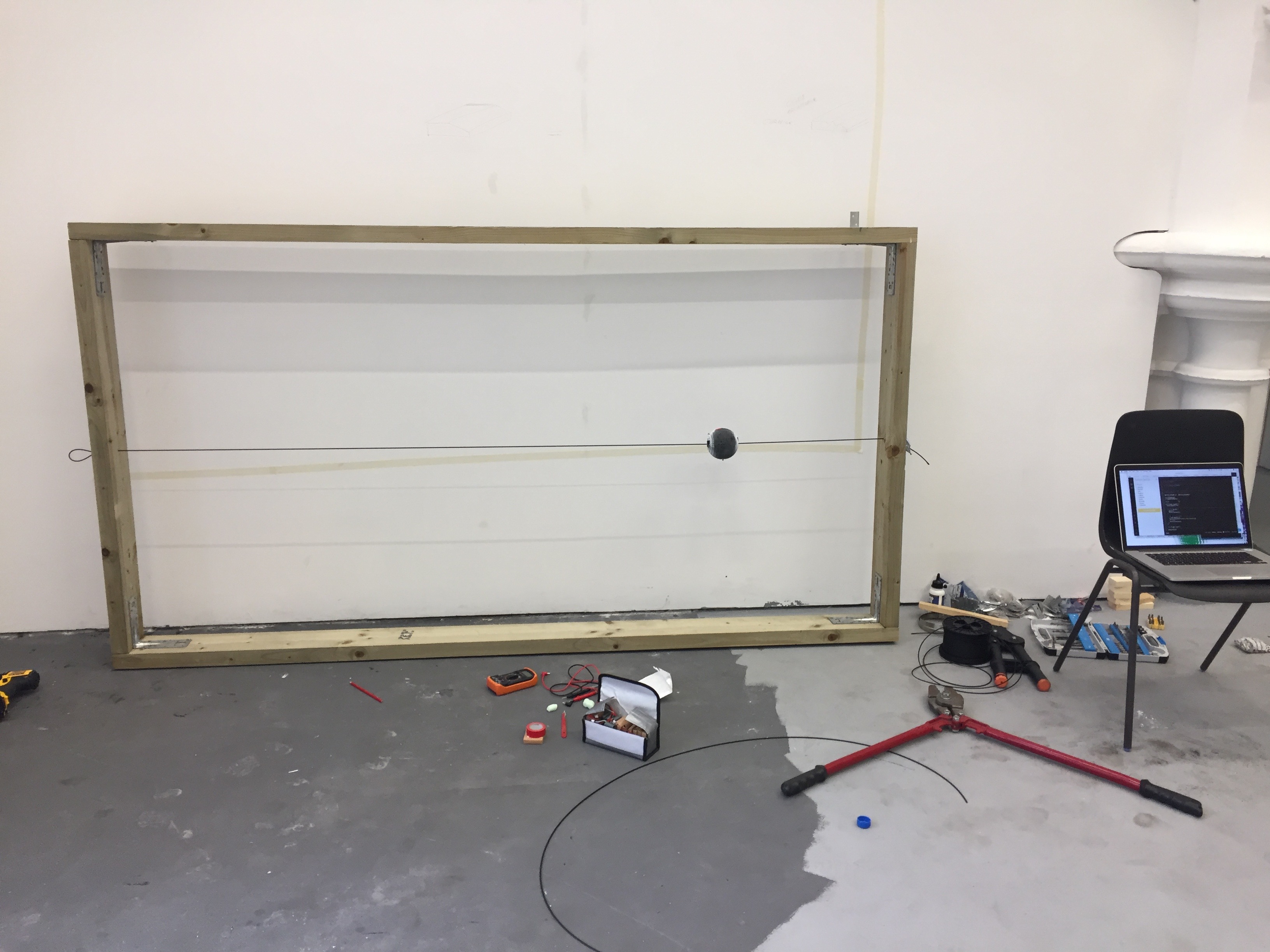
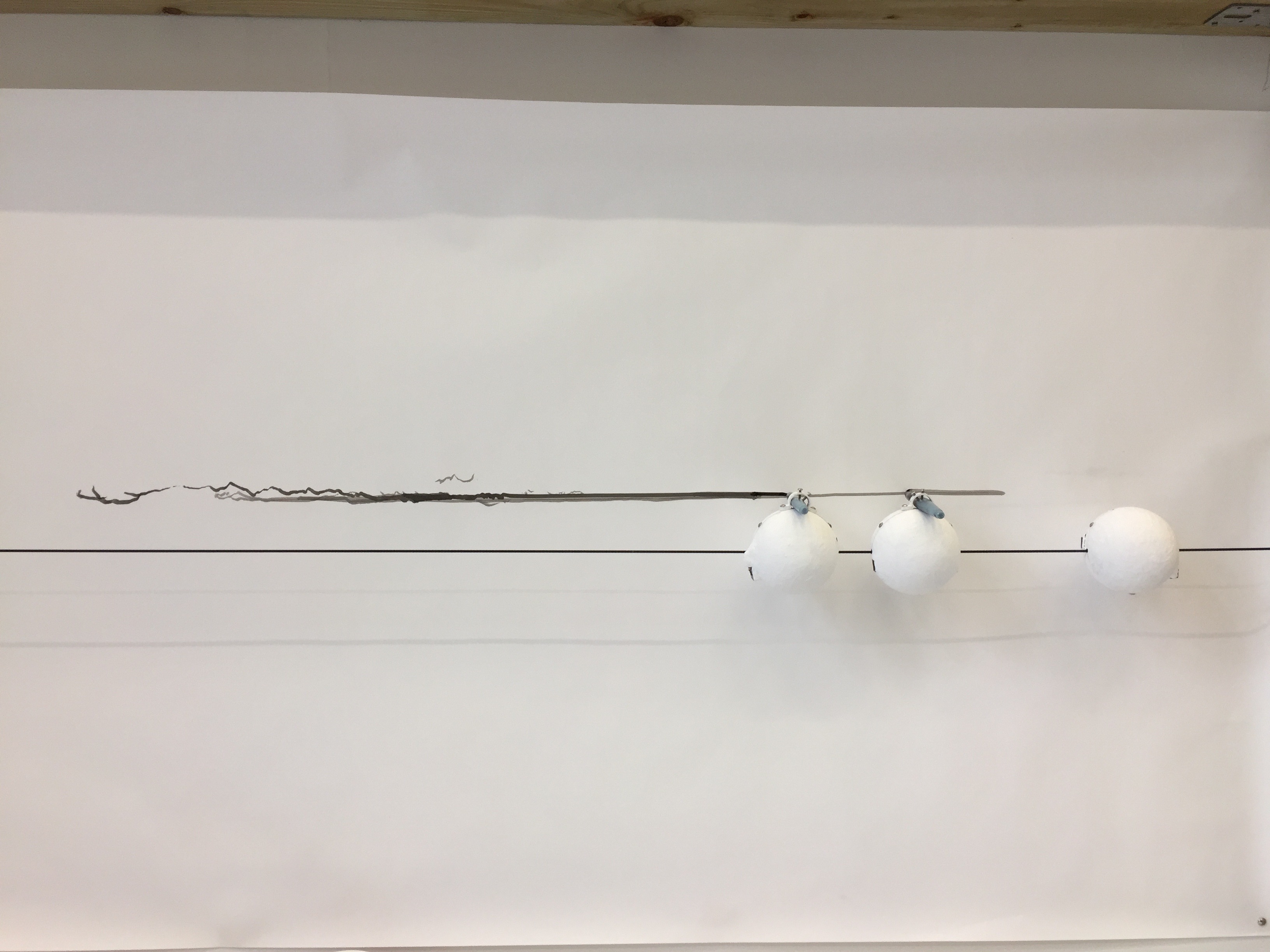
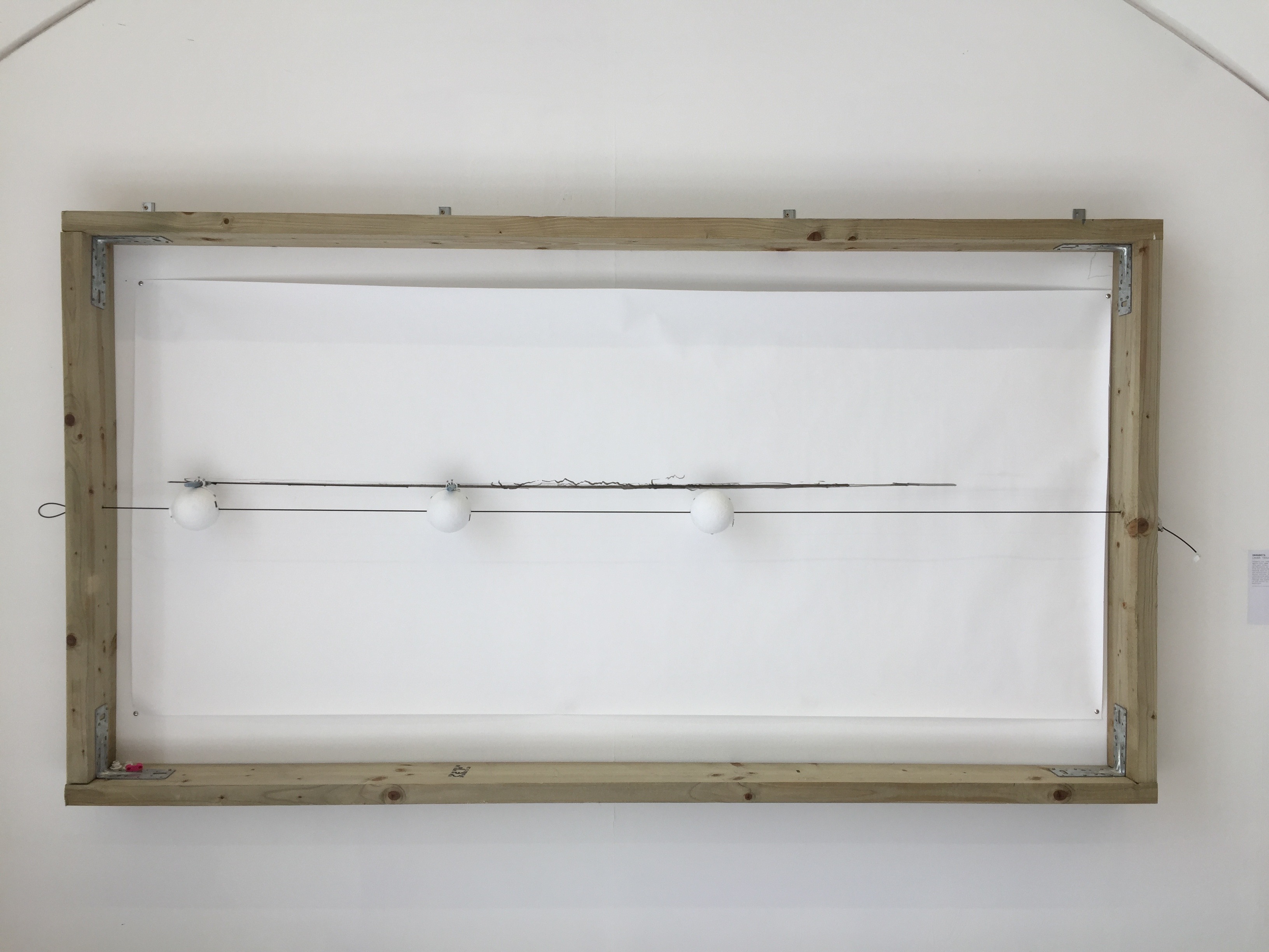
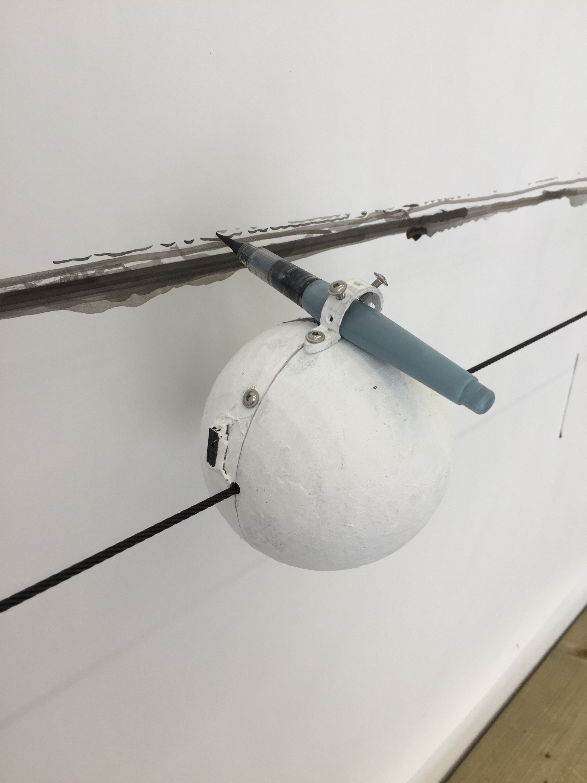
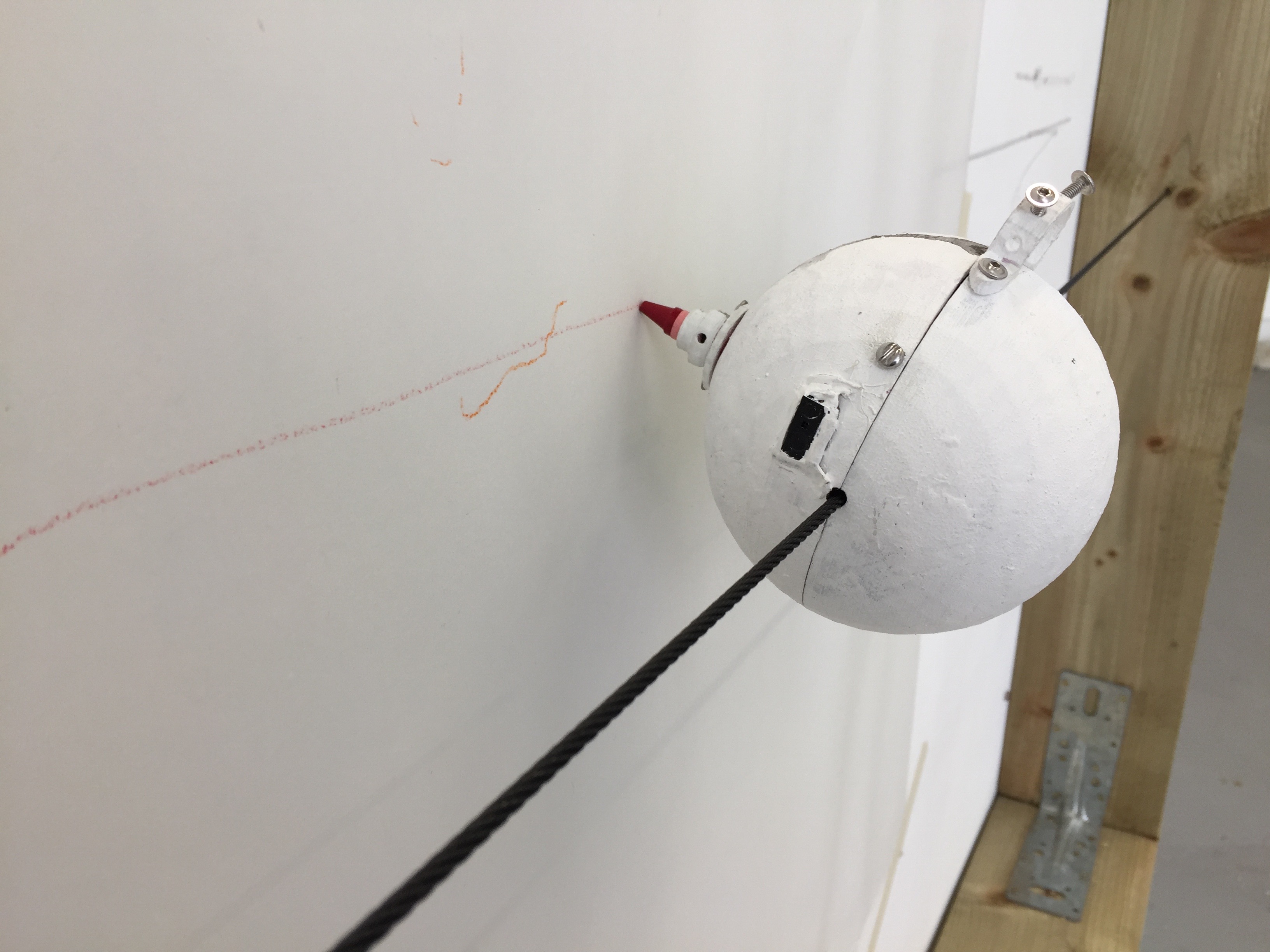
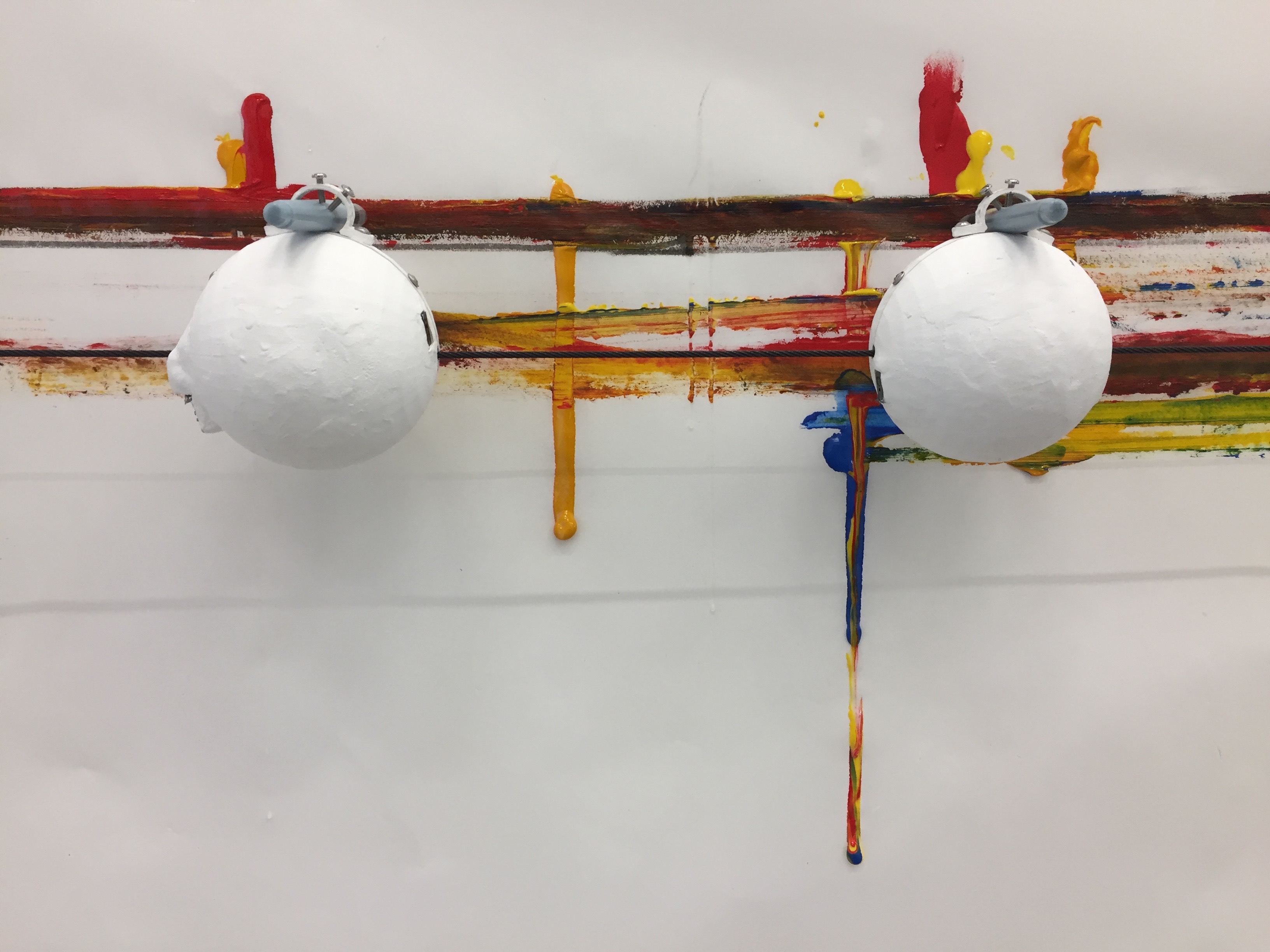
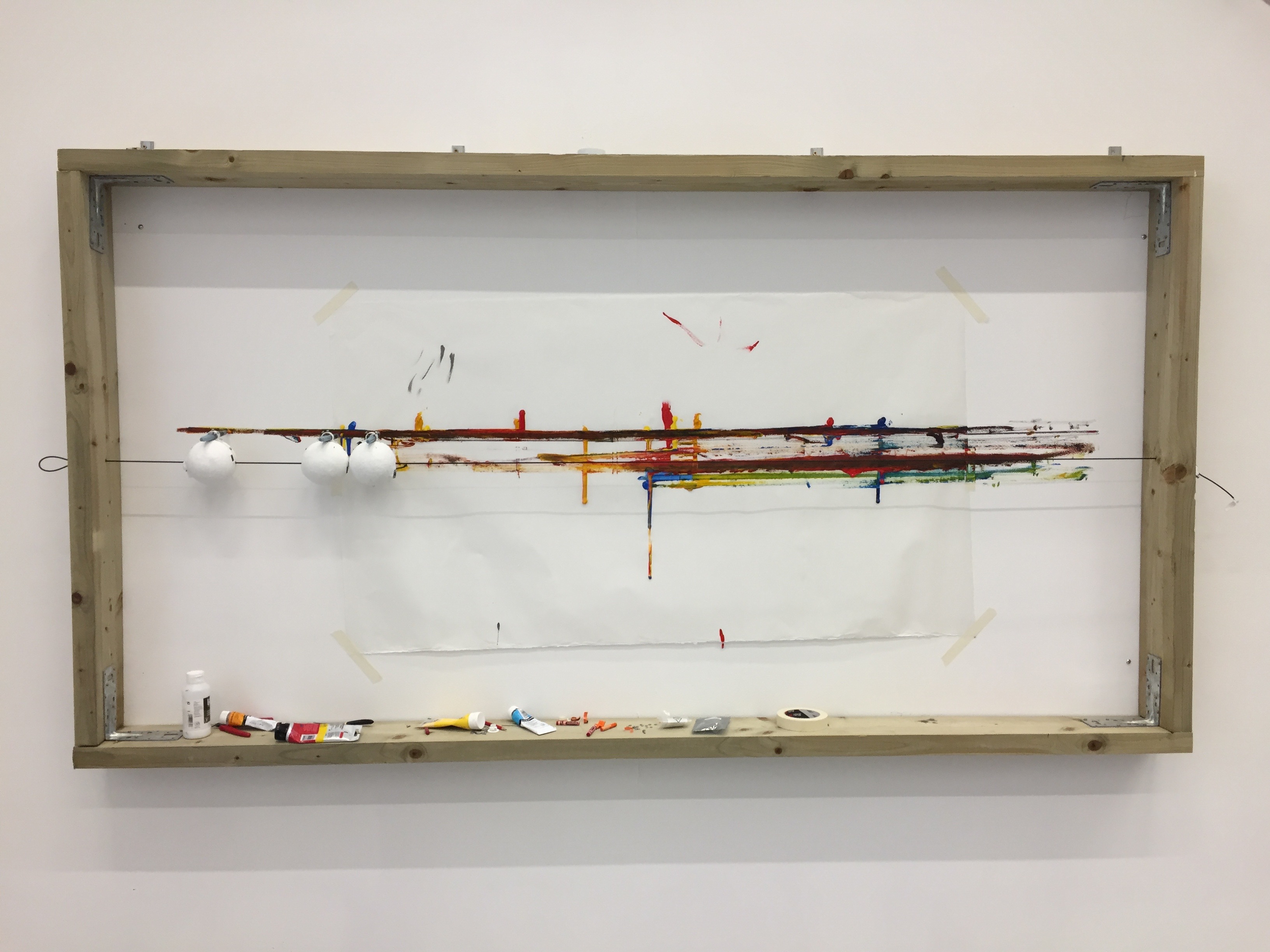
There were many other physical challenges relating to the DrawBots themselves. The tautness of the wire affected their functioning and I conducted several experiments around this. The required depth of the frame to ensure the sensors could detect the edges, whilst leaving enough room for the drawing attachments needed consideration. It was determined that a frame greater than 10cm in depth with the wire 7cm from the paper were the optimal dimensions. How they were to draw and maintain their balance was another challenge. To allow the DrawBots to draw with a range of instruments, I created a hole along the paper-facing side with an attachment as well as a fixture for the top which could accomodate wider items including pens. The drawing material nearest the paper protrudes only 3cm from the DrawBot to avoid overbalancing it, and the drawing material at the top sits as near to the center of the shape as possible.
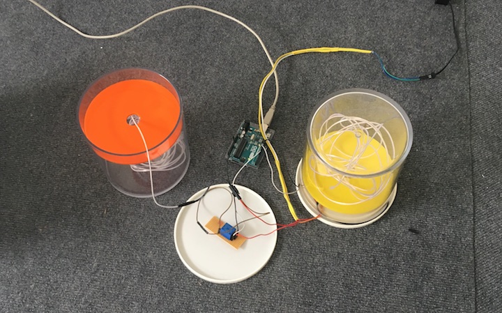
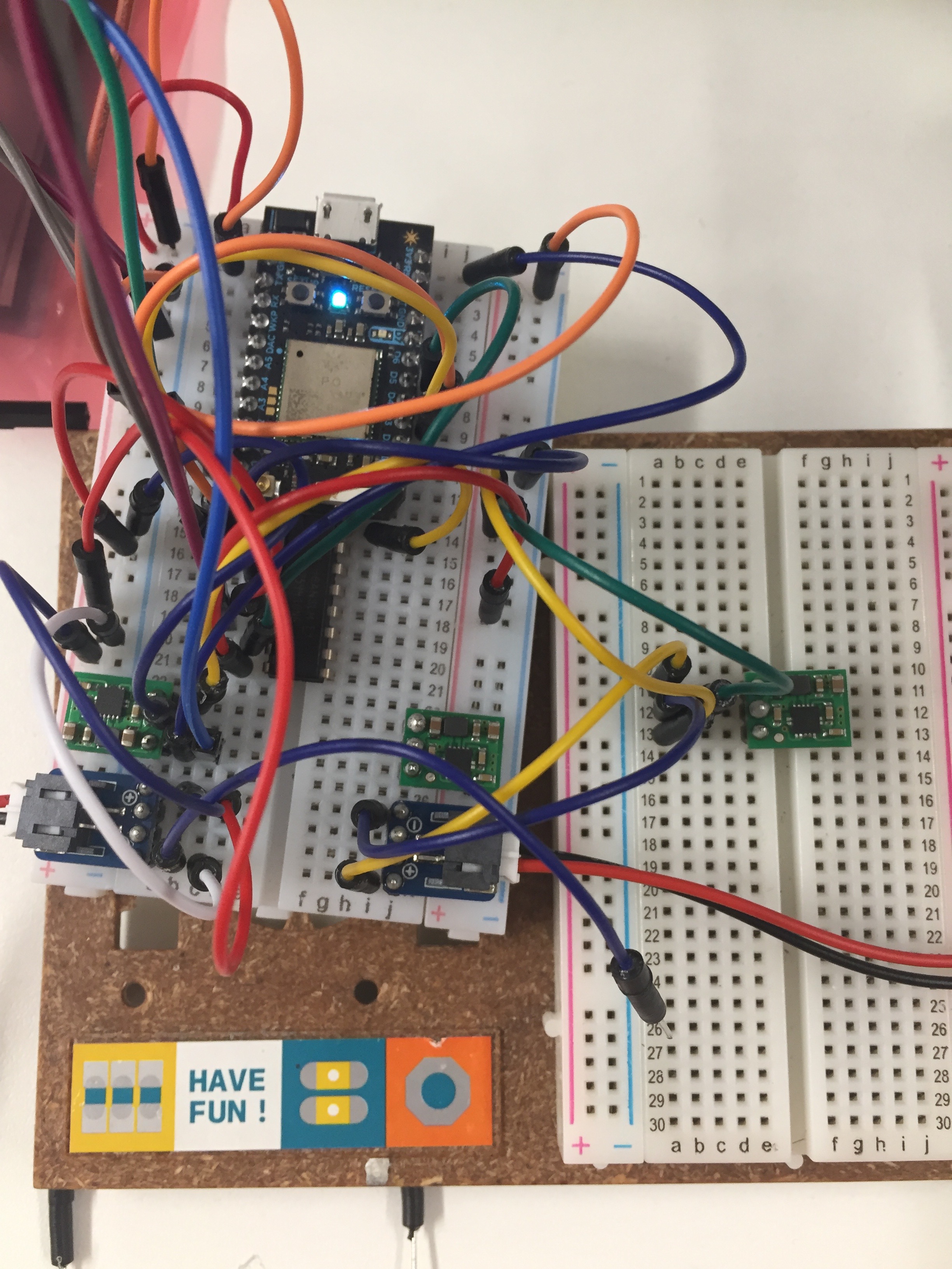
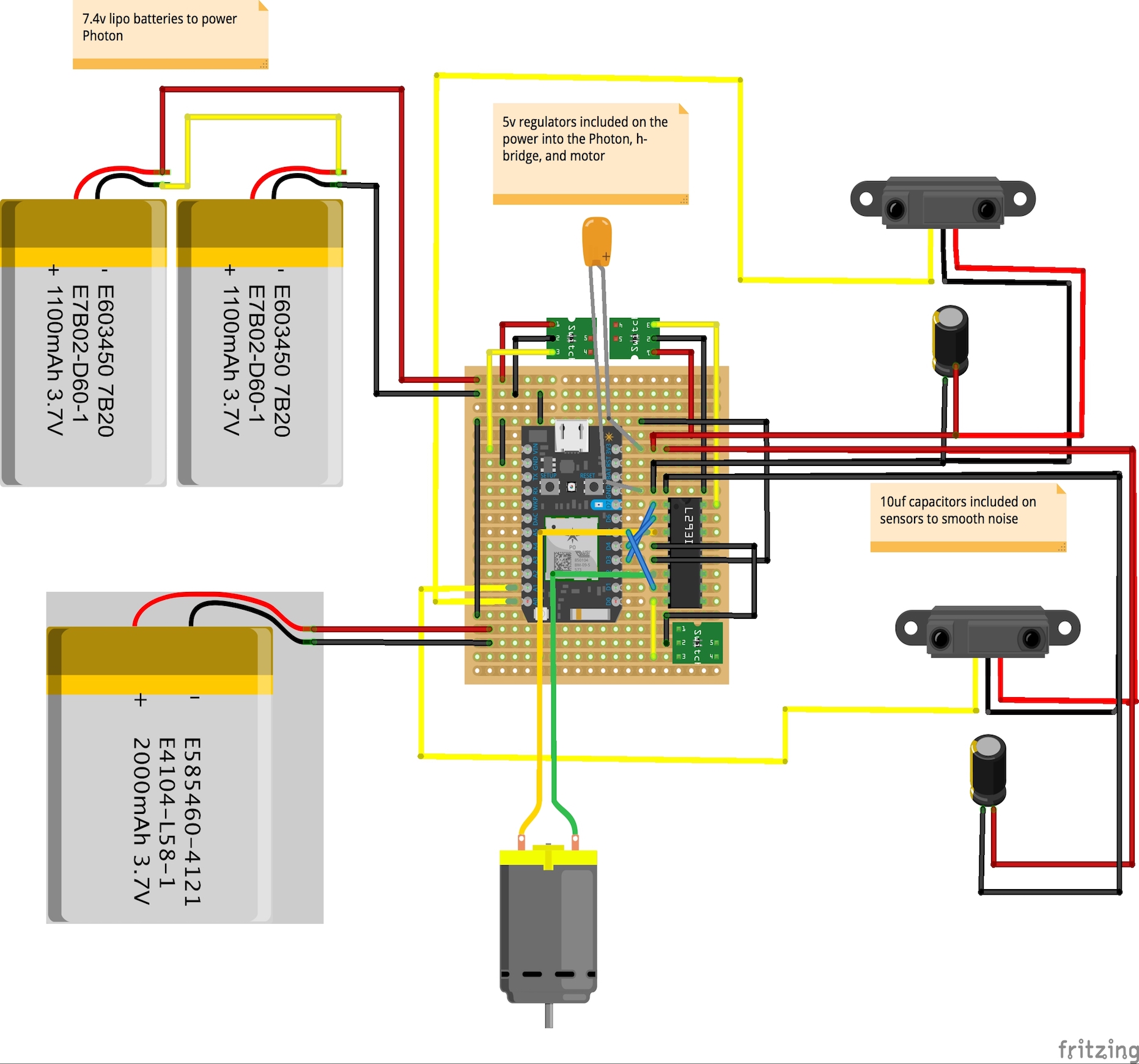
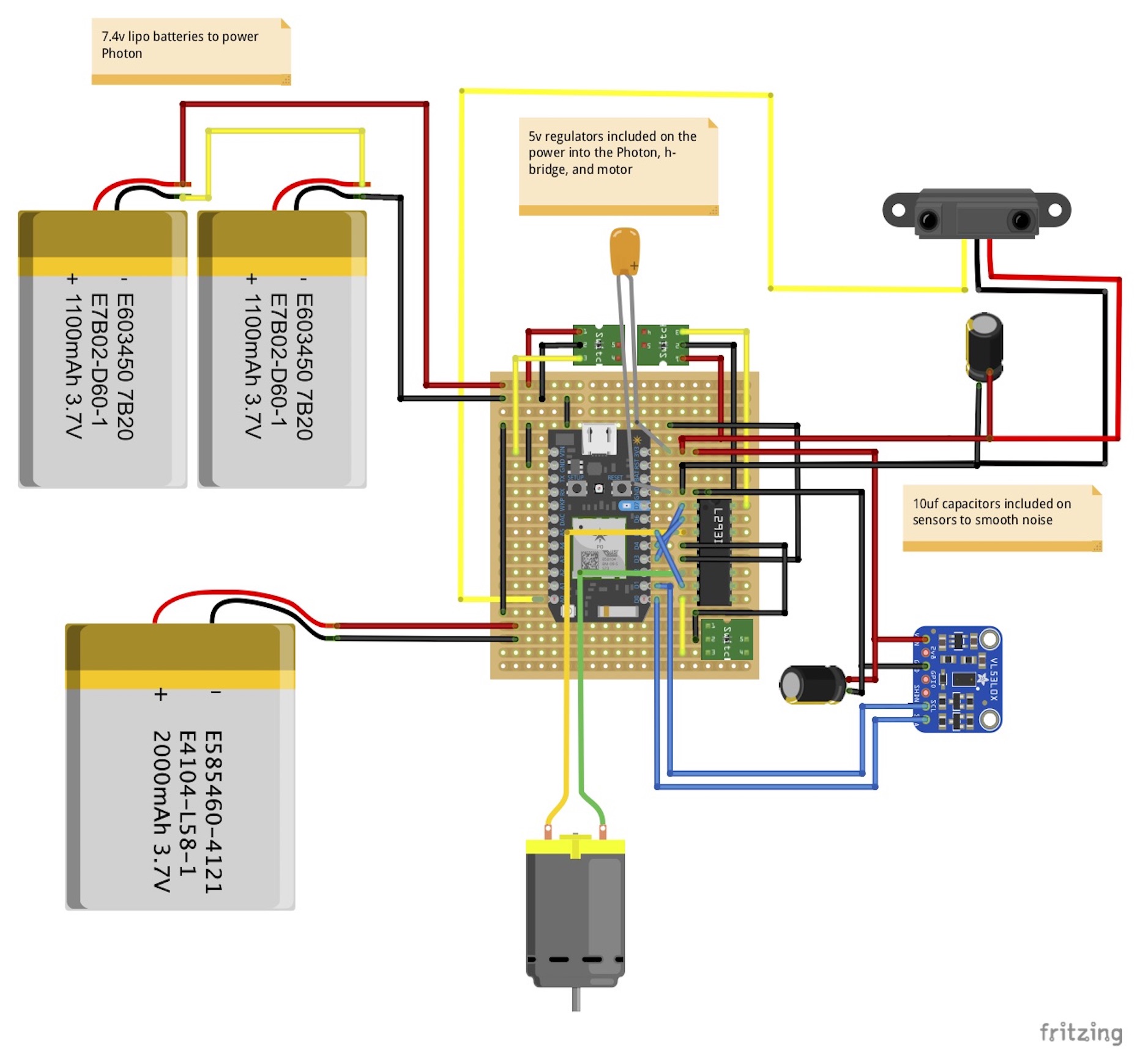
Power
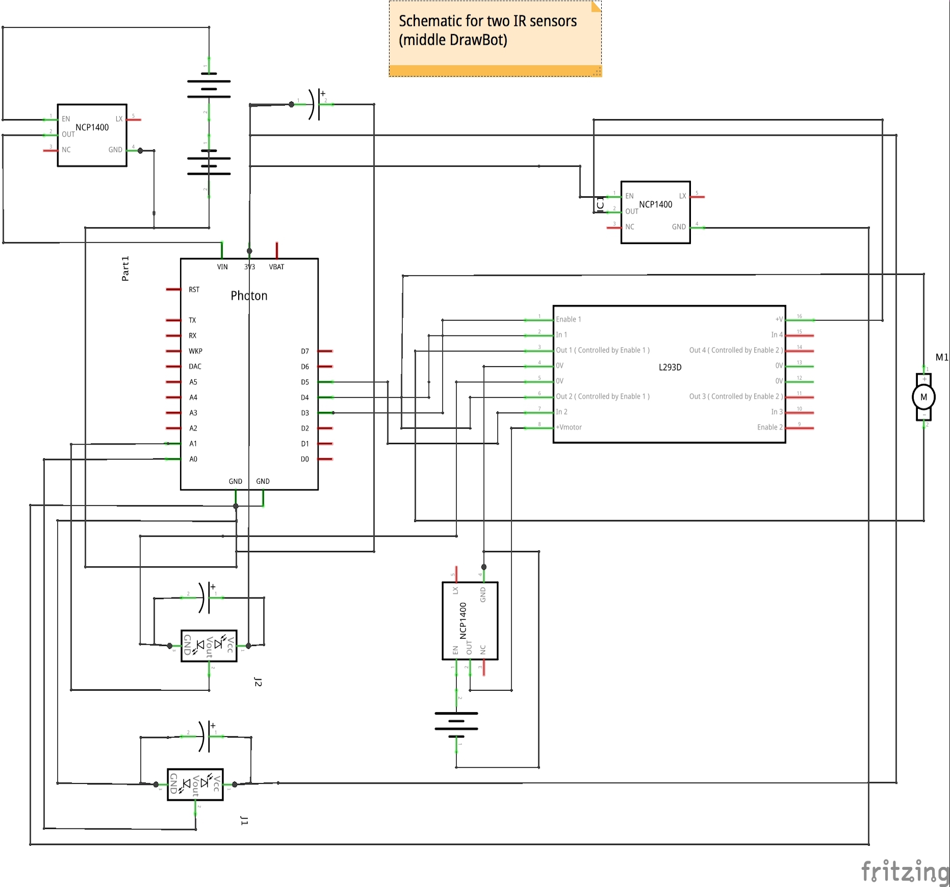
It was necessary to take into account multiple competing limitations when exploring how to power the robots. Two separate power sources were required to reverse the polarity of the voltage, and, therefore, reverse the revolutions of the motor. The Photon could tolerate 3.6v-5.5v, whilst the motor required around 6v to achieve the desired motor speed. In addition to this, the shell of the robot was 10cm in diameter, the motor could carry up to 5kg before stalling, and the robots needed to run at least 12 hours before being charged. Over the course of a series of timed experiments, I determined that the Photon with a time of flight sensor and infrared sensor required approximately 145mA per hour and the motor required roughly 80mA per hour at 5v.
I explored power banks and cell phone batteries, lithium ion batteries, and NiMH batteries. I also tested 9v batteries on the motor only which ran for 3 hours. In the end I settled on lipo batteries as the smallest, lightest option. The next issue was how to achieve over 5v from a battery type that comes in 3.7v cells. I considered connecting lipos in series myself to increase the voltage, but concluded that was probably not a good idea for a beginner. In addition, the question of safety and monitoring of batteries that can become unstable or be harmed when over-discharged below around 3v per cell was another issue to consider given the robots are remotely operating. I ultimately selected a 1200mA 7.4v 2 cell lipo (2S) and a 2000 mA 3.7v single cell lipo (1S) as the best options for size and weight with inbuilt circuit breaks for when the voltage per cell drops below the required levels.
Rather than having 2 heavy 7.4v lipos I used a 5v step-up voltage regulator to achieve a higher voltage for the motor from the lighter 3.7v lipo. The regulator operates to output 5v from input voltages between 0.5v to 5.5v. I then used a 5v step-up/step-down voltage regulator with the 7.4v lipo which powered the Photon to ensure that it had a steady supply of power within its ideal range. These regulators also act to steady voltages when an irregular power supply is being used, such as from a battery which may start above and end below the desired voltage level. I determined on this combination through a series of experiments such as this, this, and this and timing the life of the batteries.
Sensors
I considered various types of sensors for the robots including a proximity/light sensor which measures distances up to 15cm, however, when experimenting with it I found it to be too reactive to light conditions to be relied upon to coordinate robots in varying light conditions. I decided on the time of flight sensor which uses the "time of flight" method to measure the return of a laser to the sensor for its high-accuracy and lack of sensitivity to light conditions. This was instead of using more complex attachments such as an inertial measurement unit, which I concluded was not necessary when the DrawBots were moving in a restricted fashion on a wire. The time of flight sensor was placed on the DrawBots facing the frame so that the DrawBots could go "home" to a set 0 distance to prevent drift as the code became more complex.
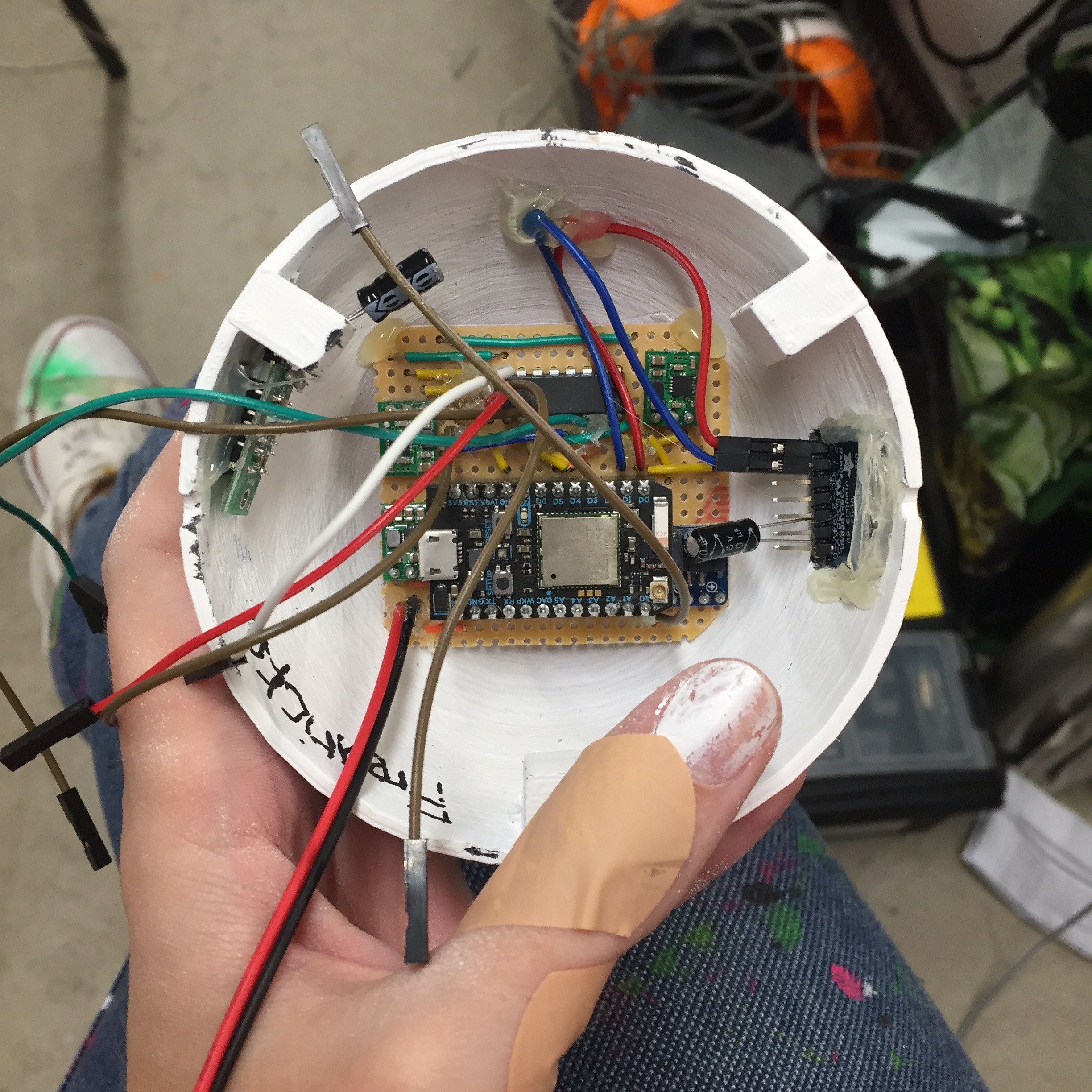
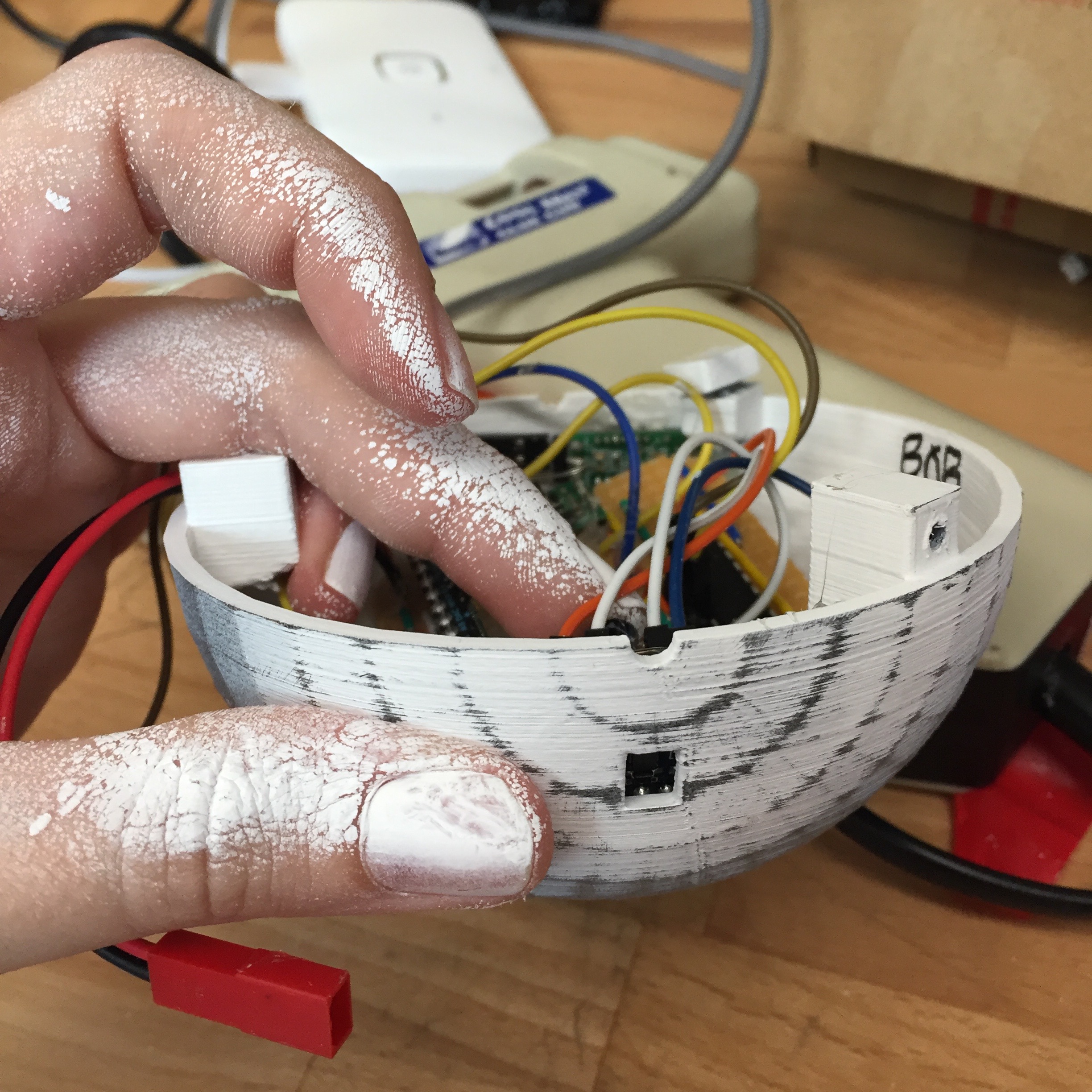
An infrared distance sensor was used on the sides of the DrawBots facing each other to allow for simple obstacle avoidance. These sensors work to detect objects approximately 10cm away and switch from 'high' to 'low' when an object is detected, without measuring distance. They are very simple in this respect, but particularly sensitive to circuit noise especially when near the batteries which made them unreliable. A 10uf decoupling capacitor was therefore placed between ground and power on the sensors themselves to smooth the noise and a 0.1uf capacitor was placed near to the microcontroller ground and power to capture varying noise frequencies. This ensured that the sensors operated reliably when enclosed in the robots near the batteries. In addition, the sensors are sensitive to surrounding light and color. The greatest accuracy was achieved when the opposite surface was white and I tuned the sensors so that their trigger point covered light conditions from morning to evening by testing them as much as possible in the space.
Communication and Code
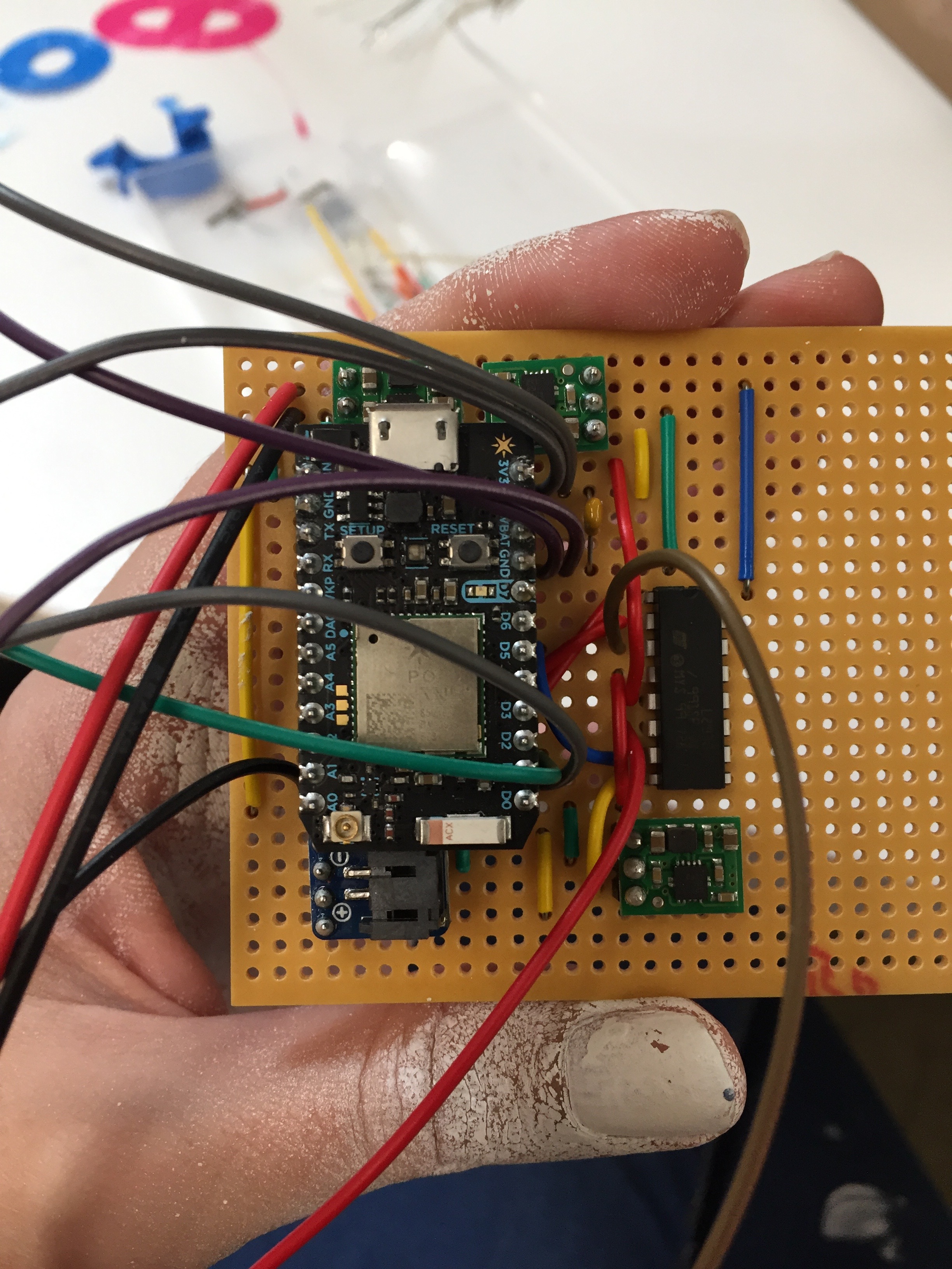
Photon microcontrollers were used because I found radio communication to be unreliable with my prototypes and not suited to managing more than a few robots as different frequencies would need to be used for more complex chains of communication. I also wanted compatibility with Arduino for simplicity. I explored using publish and subscribe events between Photons which would have enabled complex communication to develop between the DrawBots, making them more independent.
To ensure that the motors could rest and the batteries be preserved, the DrawBots work on a 3-minute cycle so that for 1 minute out of 3 the Photons are sent into deep sleep dropping current consumption down to around 4mA and ensuring that the Photons wake up at the same point in the code. The DrawBots operate in a perpetual state of boolean reverse once the first sensor trigger has taken place and require at least a 3-second space between sensor triggers to allow for the motor to take the robot away from the object before reverse is triggered again.
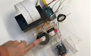
A button was developed so that the Photons could be turned off and on remotely at the start and end of each day for simplicity for the same reasons. In addition, a home function was developed using a simple count function and data from the time of flight sensor to determine whether the DrawBot was moving away or towards "home" (50mm from the edge of the frame) by determining whether numbers from the sensor were increasing or decreasing. When the DrawBot reached 50mm, it would go to sleep and mean that a 3-minute cycle would not have been used. This behaviour would have been triggered by one robot by publishing an event the other robots subscribed to and calling the other DrawBots home. It was likely this call would have been triggered by a reverse count function also developed so that, for example, after 10 motor reversals one DrawBot would tell the other DrawBots to go home and go to sleep for a few minutes to rest their batteries. I was trying to implement a finite state machine so that the loop could be exited when a function was called and re-entered at the same point, however, I could not complete it in the time I had.

Future development
DrawBots were developed to communciate with each other and coordinate themselves independently and, in this way, continue to play with the idea of removing the artist from art. As it was not possible to implement the code I had developed for this purpose, future development for this project will see communication develop between the DrawBots so that they begin to move further away from my influence. One possible expansion is to further develop the physical manifestation of my creative fine art system embodied in the DrawBots, for example, DrawBot manages time and communicates and somewhat coordinates the other bots, and the other DrawBots represent other aspects of drawing with a more complex range of materials or behaviours. I was also surprised by my own interaction with the DrawBots and the way I naturally worked with them, further developing this aspect of the DrawBots and the idea of more collaborative working is a probable direction.
Developing vertical movement, or arranging the wire in different ways is another direction I want to explore so that the art produced can grow in complexity. Removing the DrawBots from wire and having them roll freely on the floor, perhaps through paint, or chase people and create movement that way is another consideration. Line following robots is another idea to explore as the robots could follow the lines that other robots have drawn but with variations. A digging robot that digs through layers of paint on a canvas, excavating it, or perhaps erodes a block of plaster of paris over time through repeated movement are other ideas I have. I also continue to be intrigued by the idea of vacuum drawing robots which would mean the wire could be removed and the work still be vertical.
DrawBots began as Balancing Robots and initial research around the DrawBots focused on developing the balancing aspect of the one-wheel design further or on their appearance and effect. I still want to explore this direction and bring together the idea of simple, or traditional, wooden toys with electronics to create simple, more obviously balancing sculptural forms.
Self evaluation
The DrawBots physically worked very well - the 3D printed shell maintained its integrity throughout and the sensors worked reliably. The batteries and voltage regulators worked perfectly and lasted well over 12 hours a day. However, the batteries, particularly the 7.4v lipo take up space and weight and require tending to every day or two for charging and checks. I will look at the DrawBots taking their electricity from the wire they run along (assuming they continue to move along wires). This will take a significant amount of weight out of the shape and mean that the bots could likely move vertically for long durations of time. Alternative sources of power such as solar could also be useful to look at if that takes up less weight and space.
I found on a couple occasions that the bots could become stuck together for a short time within the 3 second sensor check before moving away from each other. This is likely because the motors ran at the same speed between the 3 robots and each had a 3 second timer check, some variation would likely have prevented this. The voltage regulators should have prevented any voltage drop in the batteries impacting the speed of revolution of the motor, however, there did seem to be some very slight variations between robots which could have been down to motor wear and tear which could also have influenced this. Increasing the timer check would likely resolve it, however, I quite liked this occasional behaviour.
The micro metal gearmotor used in the robots is a very reliable and strong motor, but I think upgrading this motor will allow me to do more (including vertical movement) and feel more comfortable with their durability. I really liked the work that the DrawBots produced and developing their direction of movement and drawing attachments further is something that I want to do to see what else they can draw. The most challenging aspect of the DrawBots was, in some ways, giving up the intra-robot communication I had been working towards and giving up the number of DrawBots I had been planning to make. However, I am very happy with the DrawBots and how they operate and I achieved them by changing my plan and sticking to it.
References
1. Laura Traver, Balancing Robots, http://doc.gold.ac.uk/compartsblog/index.php/work/balancing-robots/
2. Tim Youngblood, How to Control a DC Motor with an Arduino, https://www.allaboutcircuits.com/projects/control-a-motor-with-an-arduino/
3. W Durfee, L293 Motor Driver and H-Bridges, http://www.me.umn.edu/courses/me2011/arduino/technotes/dcmotors/L293/L293.html
4. Photon datasheet, https://docs.particle.io/datasheets/photon-(wifi)/photon-datasheet/
5. Micro metal gearmotors, https://shop.pimoroni.com/products/micro-metal-gearmotor-extended-back-shaft?variant=3073681153
6. Understanding Lipo Batteries, https://www.rchelicopterfun.com/rc-lipo-batteries.html
7. Power Banks, http://www.gadgetexplained.com/2016/11/how-to-power-robot-car-with-power-bank.html
8. Connecting lipos in series, https://learn.sparkfun.com/tutorials/sparkfun-5v1a-lipo-chargerbooster-hookup-guide
9. A Guide to Understanding Lipo Batteries, https://rogershobbycenter.com/lipoguide/
10. 5v step up, http://www.hobbytronics.co.uk/u1v10f5-5v-regulator
11. Proximity/light sensor, https://www.vishay.com/docs/83462/vcnl4010.pdf
12. Time of flight sensor, https://www.adafruit.com/product/3316
13. Robert Keim, What is Electrical Noise, https://www.allaboutcircuits.com/technical-articles/electrical-noise-what-causes-noise-in-electrical-circuits/
14. Decoupling capacitor, https://electronics.stackexchange.com/questions/17754/where-to-place-a-capacitor-to-smoothen-ir-sensor-reading
15. Decoupling capacitor, https://www.murata.com/en-eu/products/emc/emifil/knowhow/basic/chapter03-p3
16. Decoupling capacitors, https://electronics.stackexchange.com/questions/96574/two-bypass-decoupling-capacitors-rule
17. IR sensors, https://acroname.com/articles/sharp-infrared-ranger-comparison
18. Deep sleep, https://www.kevinsidwar.com/iot/2017/12/15/demystifying-sleep-on-the-particle-photon
19. State machine, https://www.instructables.com/id/Finite-State-Machine-on-an-Arduino/
20. Sol LeWitt, https://www.tate.org.uk/research/publications/tate-papers/14/ideas-in-transmission-lewitt-wall-drawings-and-the-question-of-medium
21. Leonel Moura, http://www.leonelmoura.com
22. Michael Quantrill, “Drawing as a Gateway to Computer-Human Interaction”, Leonardo, Vol. 35, No. 1, (2002), pp. 73-78 at p. 73.
23. Tom White, Digital Finger Painting, 2012, Ammer, Manuela, “How’s My Painting?” (Judge Me, Please, Don’t Judge Me)”, Ammer, Hochdorfer, Joselit, Painting 2.0, pp. 85-101 at p. 152.
24. Paul Klee, Pedagogical Sketchbook, http://ing.univaq.it/continenza/Corso%20di%20Disegno%20dell%27Architettura%202/TESTI%20D%27AUTORE/Paul-klee-Pedagogical-Sketchbook.pdf