
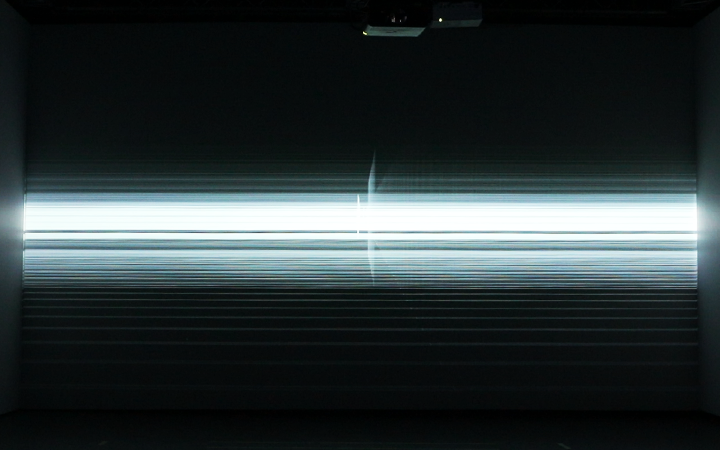


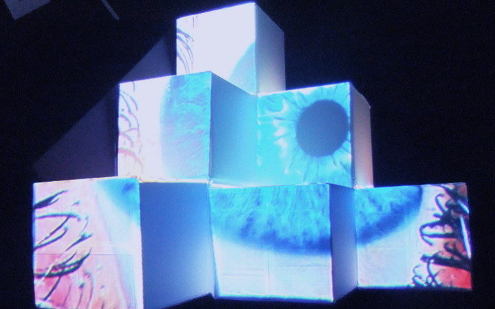
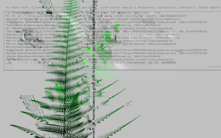


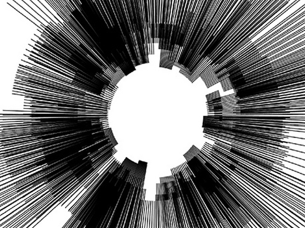

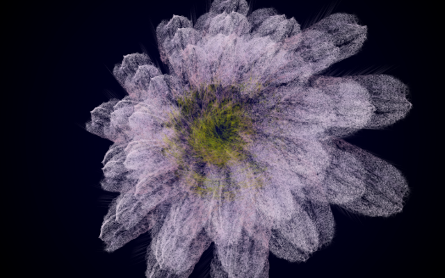


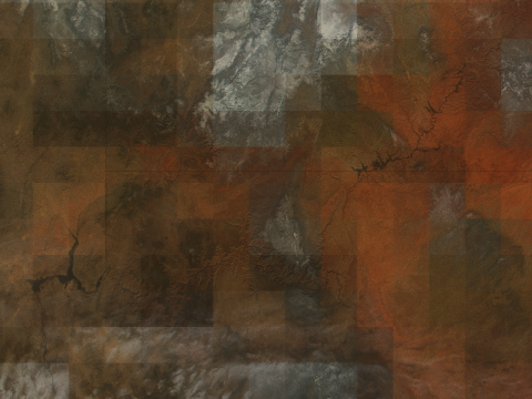


CAPTURING MOVEMENT
Converting the motion into mesh and 3d printable object. openCV + ofMesh +Grasshopper
produced by: Freddie Hong
Method
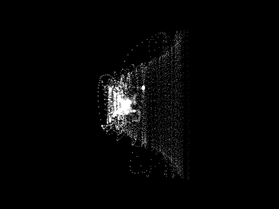
A webcam collects the information when the movement occurs. It does it by calculating frame differences which is the information of the changes made in pixels that webcam collects at each frame.
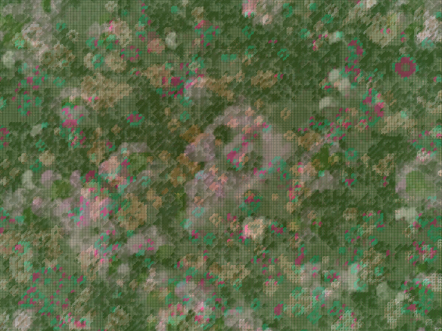
The vertices of the shape is then collected and added into a point cloud and where each points are then connected to the neighbouring points.
Z-axis moves in a time-base, that every newly added points are in a new layer, producing a time-based 3d structure.
The vertexes created at openframeworks were than exported as a .txt coordinates file which later was imported on grasshopper, a parametric plug-in for a CAD program called Rhino3d.
References
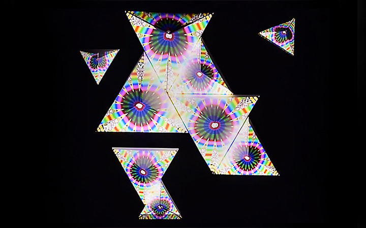
This program referenced long exposure photographs and slit scan. and is essentially a combination of slit scanning and long exposure photograph.
Slit Scan
Long Exposure Photograph
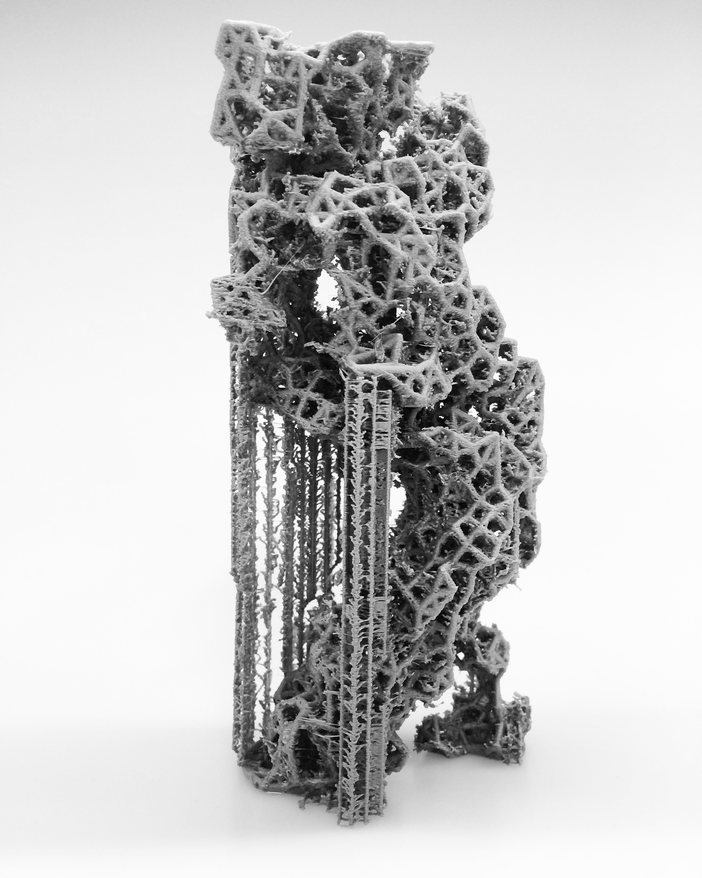
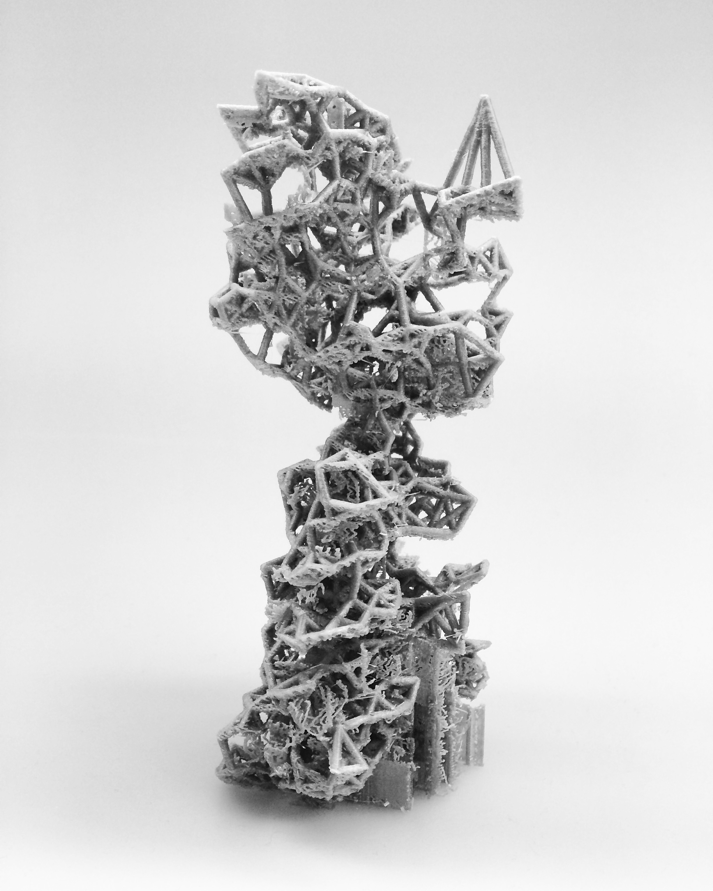
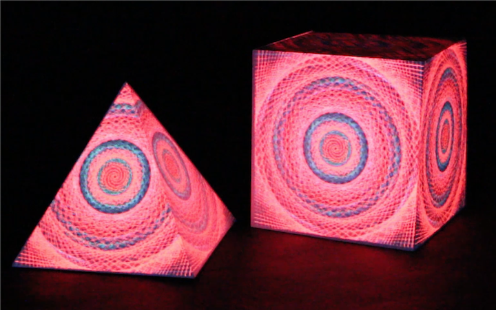
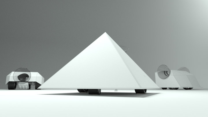
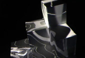
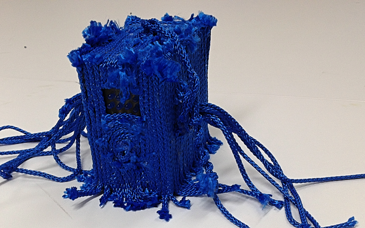
3D printed Artefacts
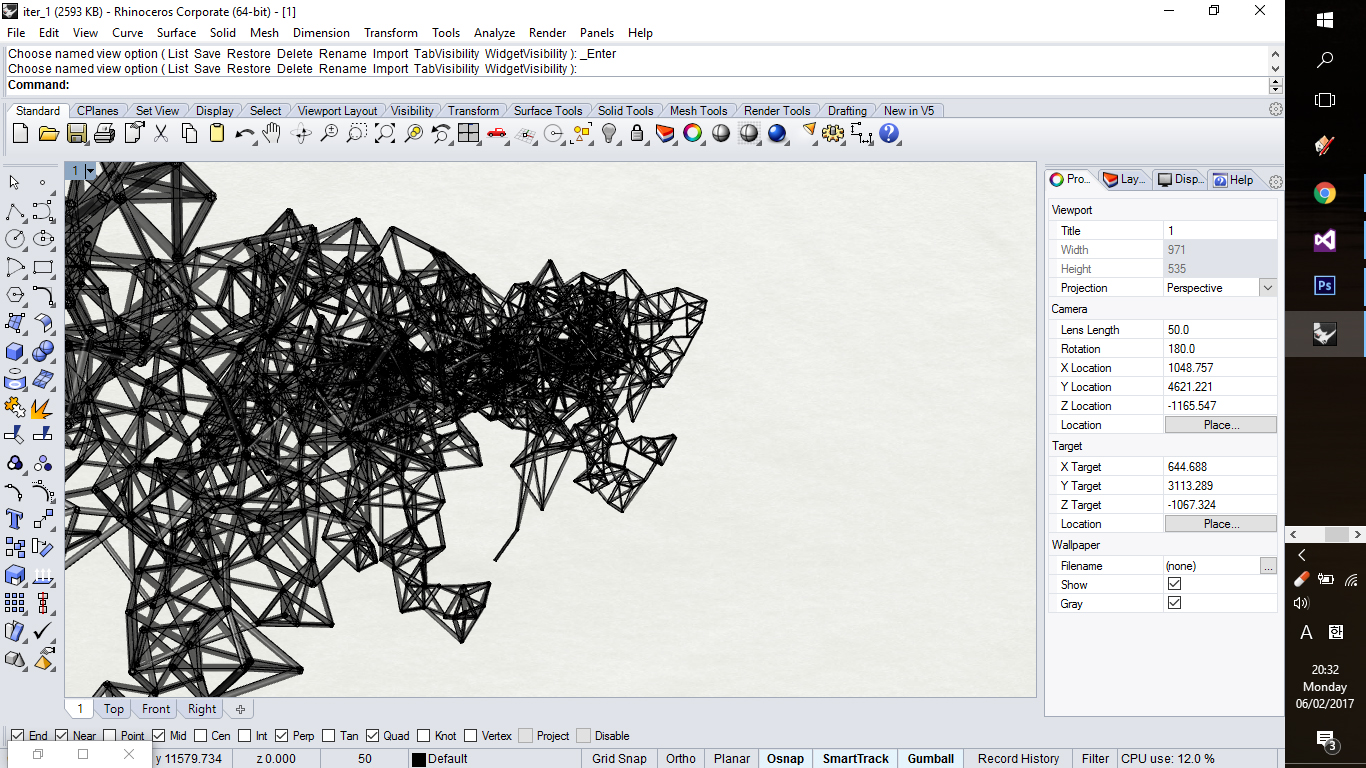
Imported Geometry on Rhino + Grasshopper
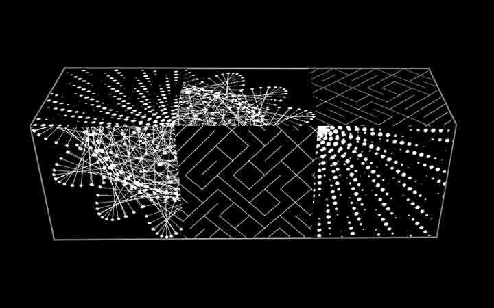
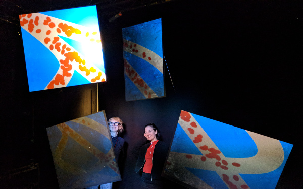
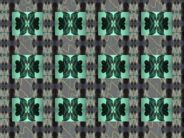
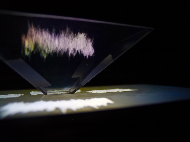
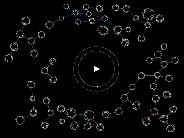
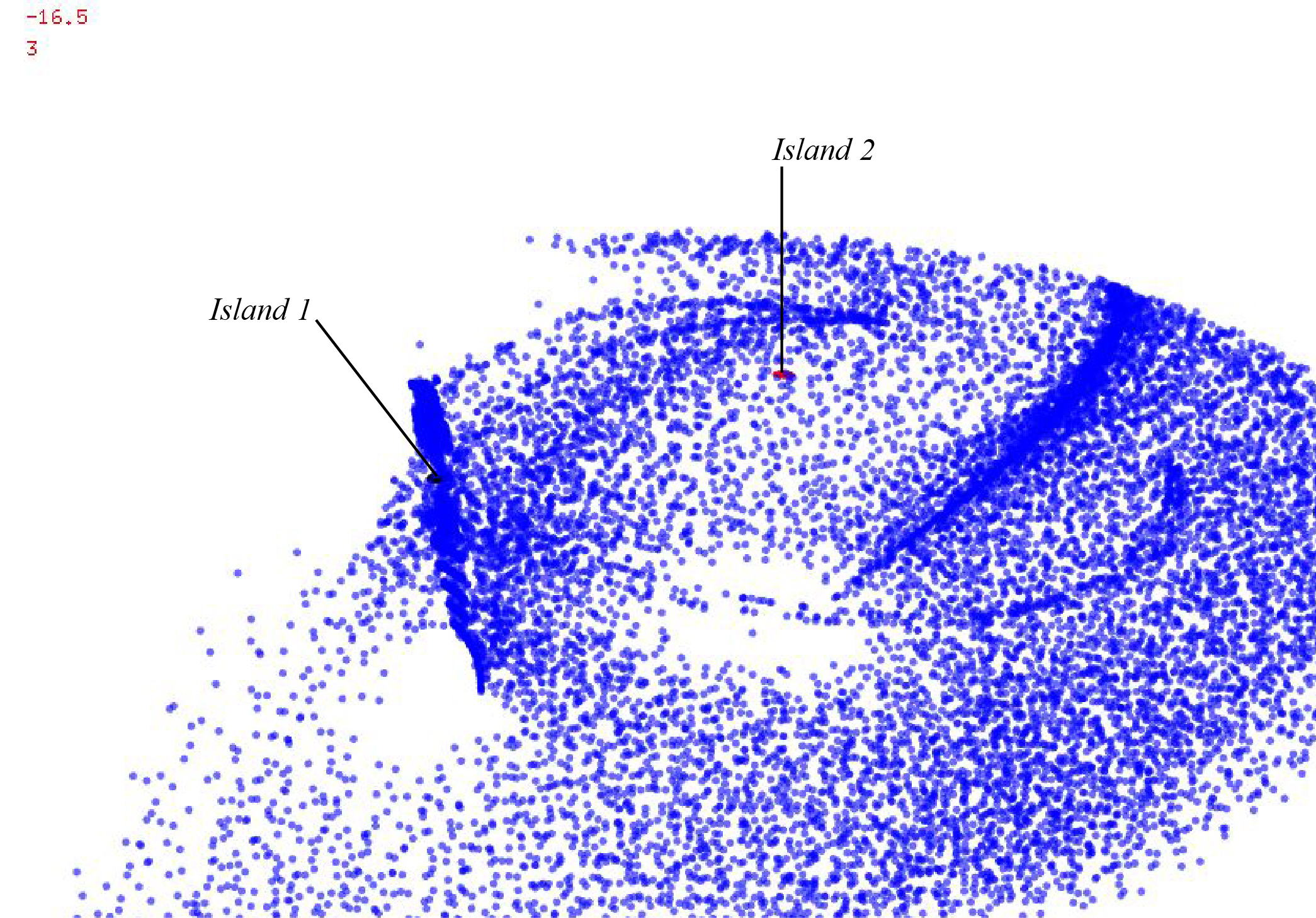
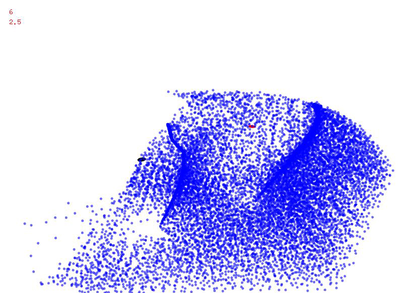
OCEAN SWELL PROGRAM
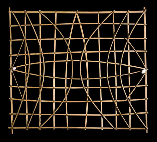
This project is inspired by the ‘Stick charts’ that were made and used by the Marshallese to navigate the Pacific Ocean by canoe off the coast of the Marshall Islands. The charts represented major ocean swell patterns and the ways the islands disrupted those patterns, typically determined by sensing disruptions in ocean swells by islands during sea navigation.
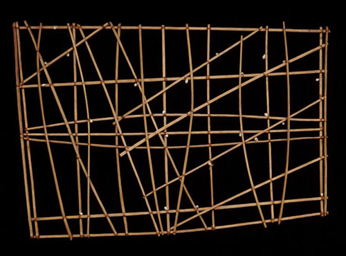
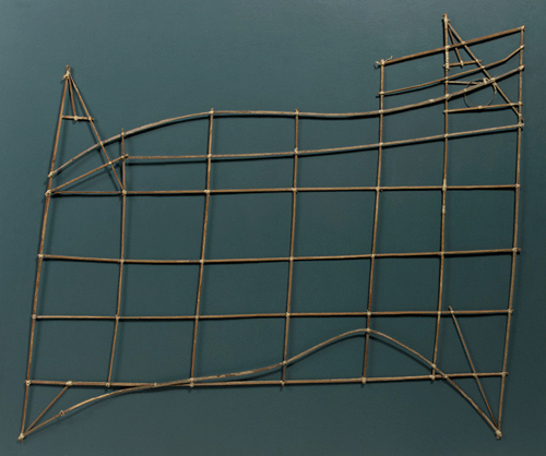
Motivation
This charts uses intuitive and inventive notation to describe the patterns of ocean swells.
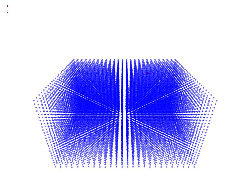
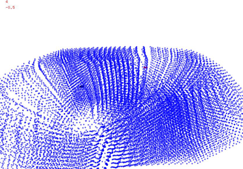
As a response to the ‘ocean swell program’ uses two different input parameters that generates a tidal wave around two given location of islands. Parameters defines the strength of the wave, i.e. the size of the island which slowly starts to deform an array of points that initially were all linearly lined up as a grid.
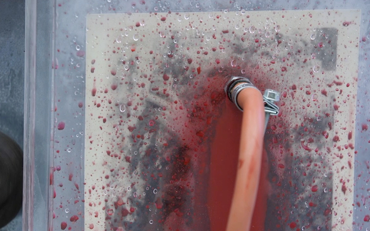
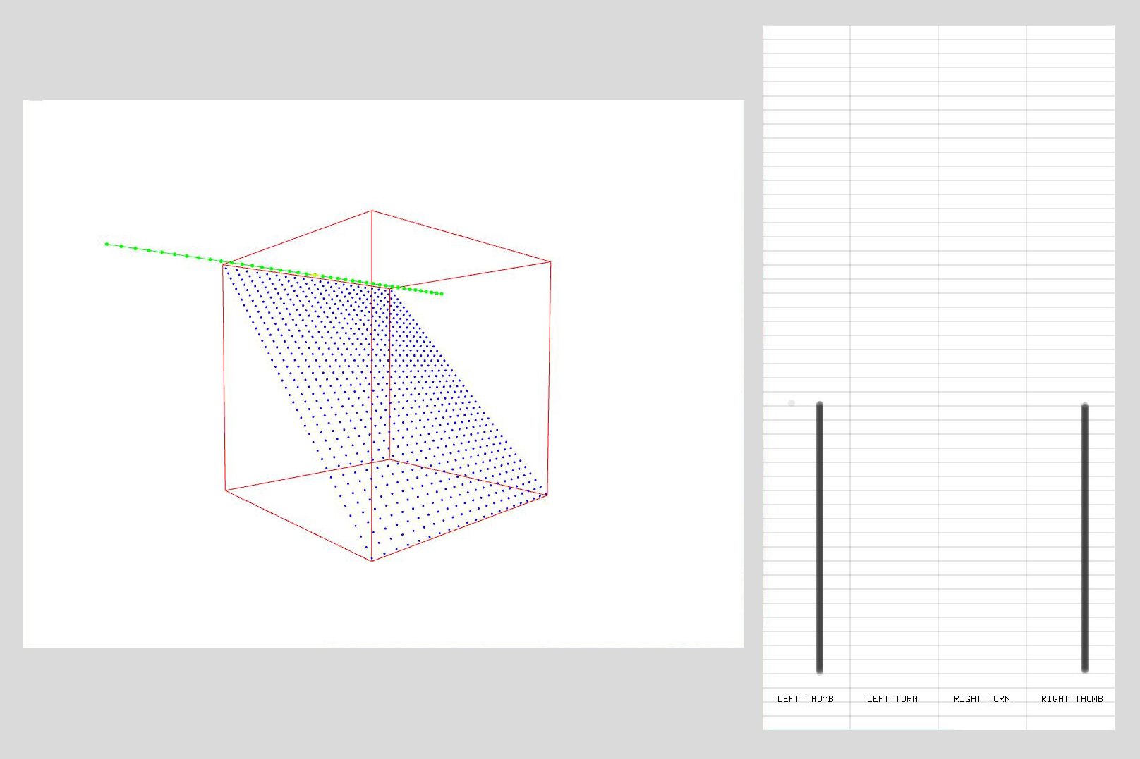
DRAWING SURFACES LIKE A GAME
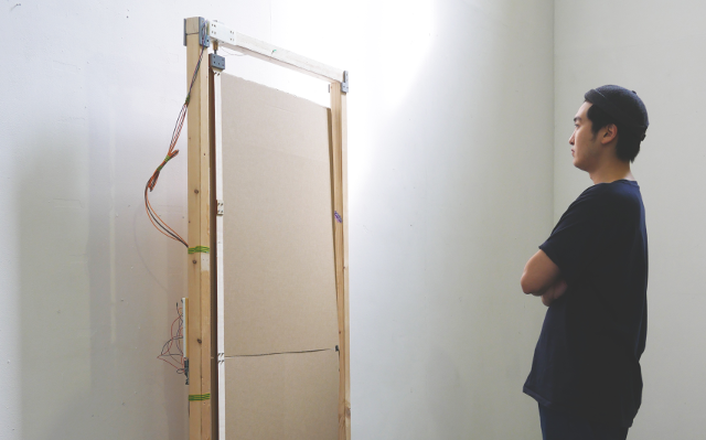
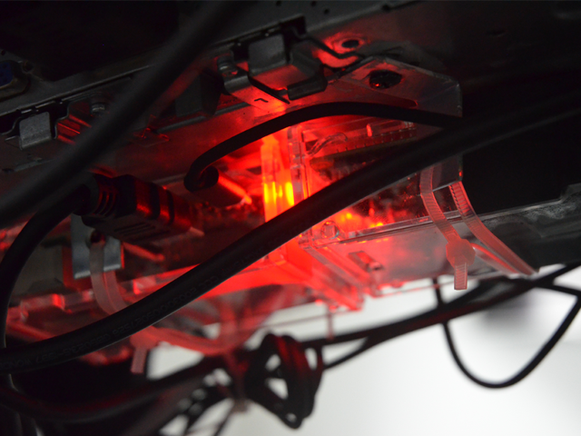
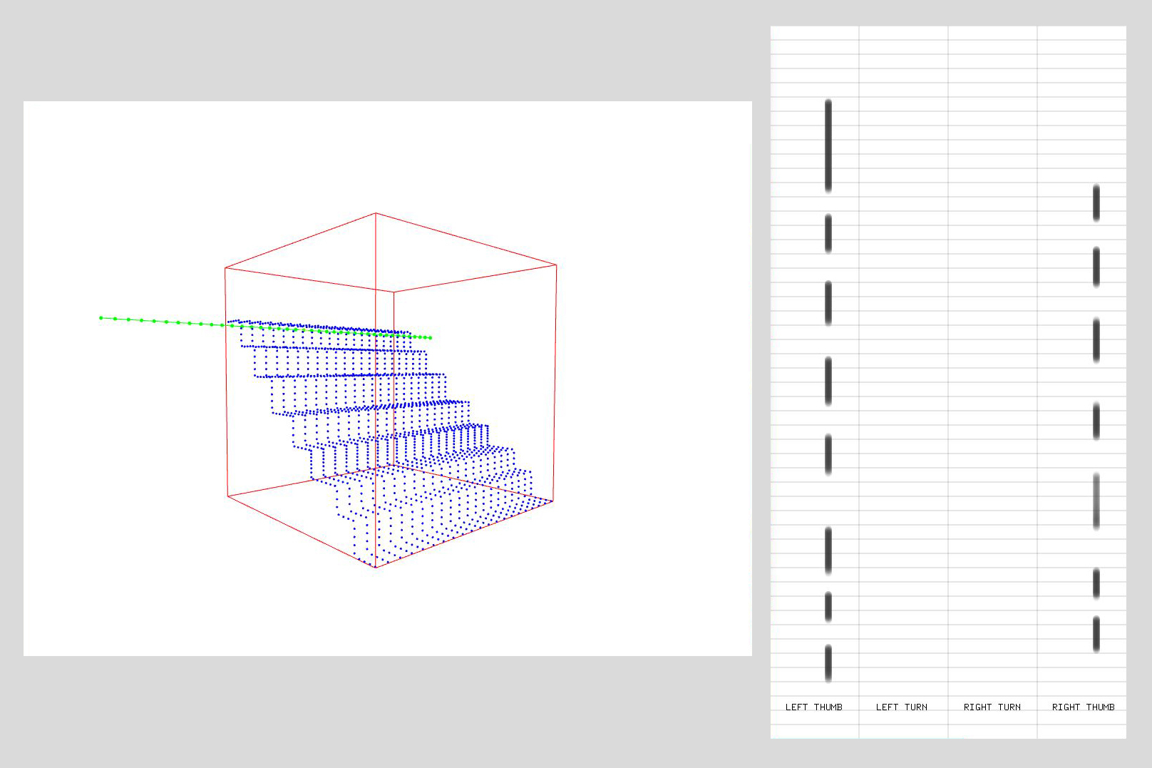
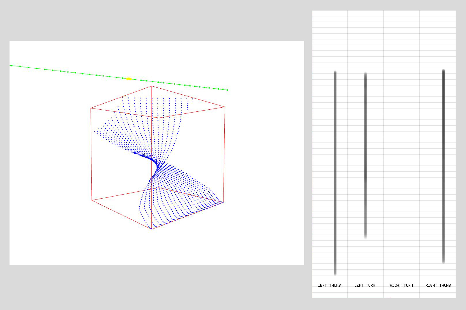
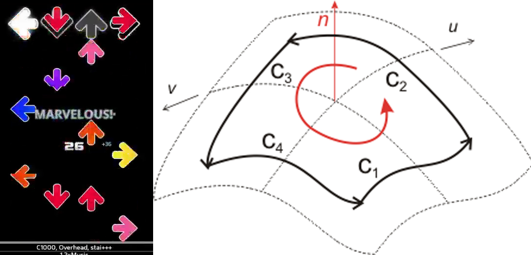
This is a small and unique CAD program that connects Xbox controller to construct a ruled surfaces.
When the horizontal bar enters the red cube it starts to generate shapes, and the user intuitively moves the rod with the game controller to create a shape.
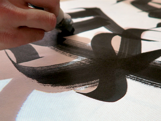
This idea of drawing surfaces using a game controller questions on the conventional method of describing and drawing shapes. Could a geometry be described and notated with a command and a score instead of mathematical quantities such as an angle and dimension? The project instead uses a ‘musical score’ or a ‘ guitar hero’ looking like notation to describe the geometry, darker the lines the fullness of the trigger i.e. faster moment of the linear wire.
If I was to recreate the geometry, I would reference the notation that is created rather than measuring the dimensions of already created geometry.
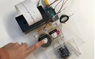
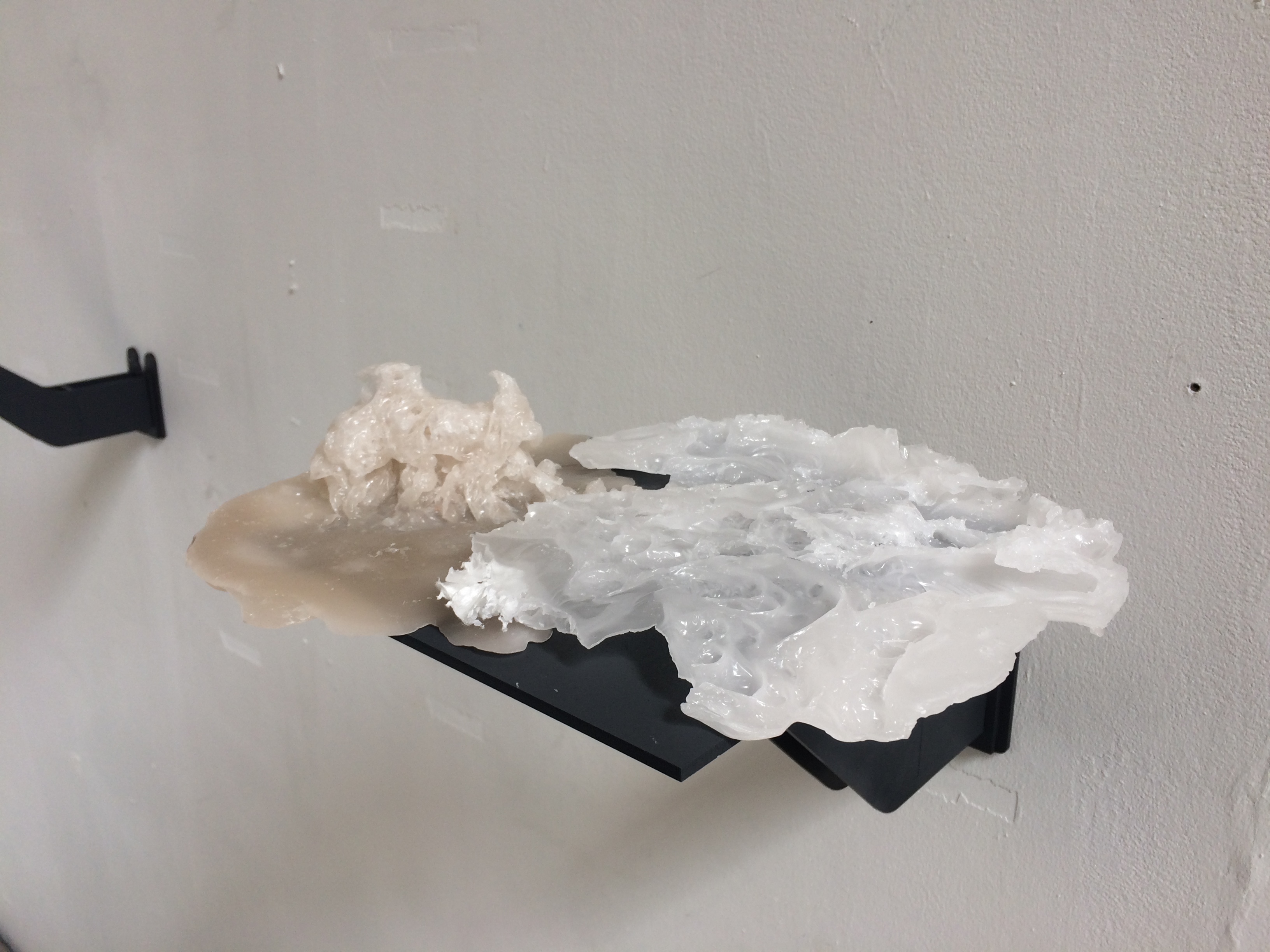
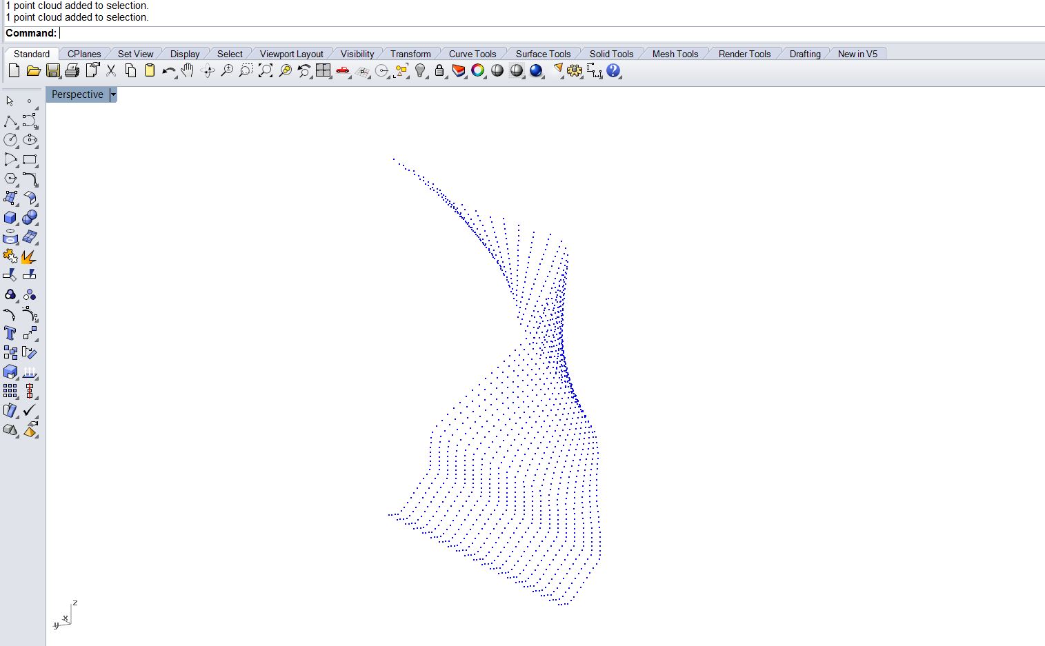
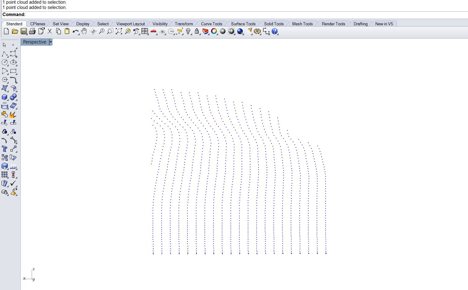
Every time the reset button is pressed, the program saves the point cloud of the surface as .ply file which could be imported into Rhino for further production.
Important Point is that these surfaces are not constructed with automated function of CAD software, but with the author’s intuition and therefore the method isn’t fully digital nor analogue but sits some where in between.
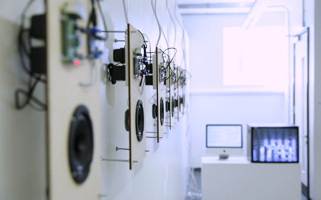
Physical representation of the point cloud
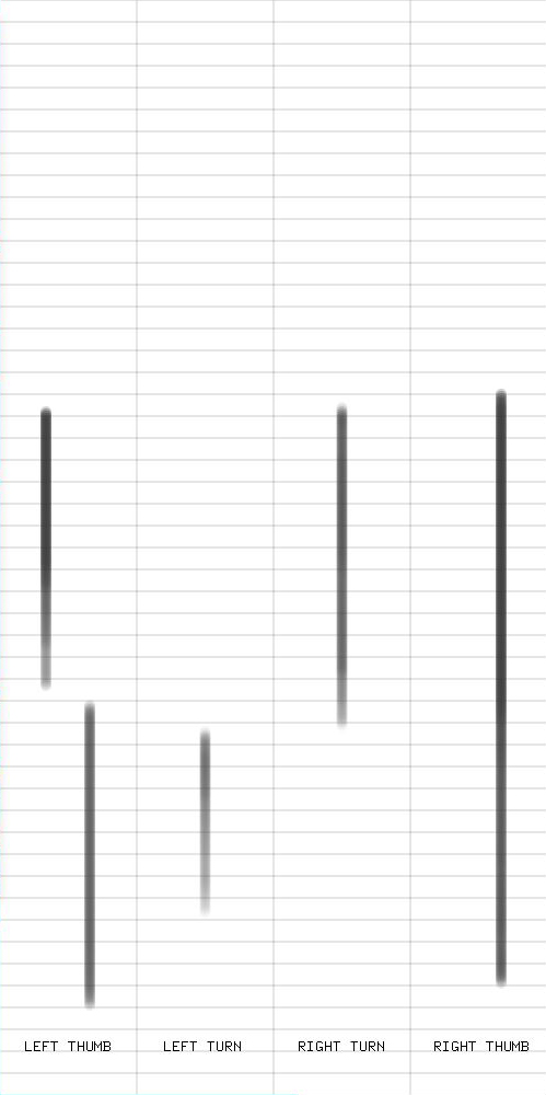
score of the surface
AddOn : ofxXboxController
Reference :
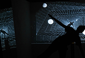
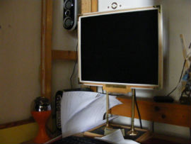
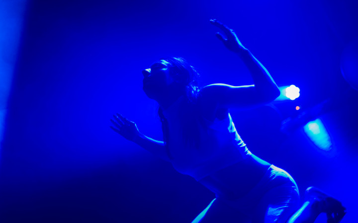
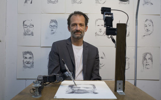
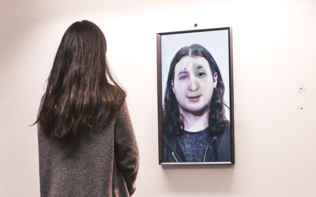
COMPUTATIONAL SENSE AND PHYSICAL MOVEMENT
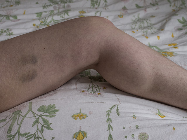
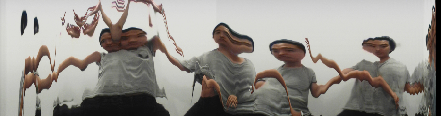
This performative project exhibits in real-time a process of a man counterbalancing with the computer motions through drawing.
The Project experiments with different computational senses, motions and analyse how different computational senses can impose different physical movements.
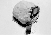
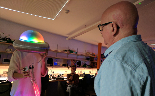
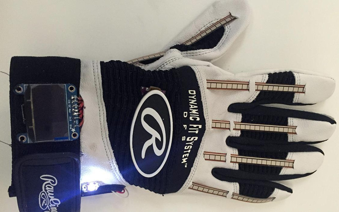
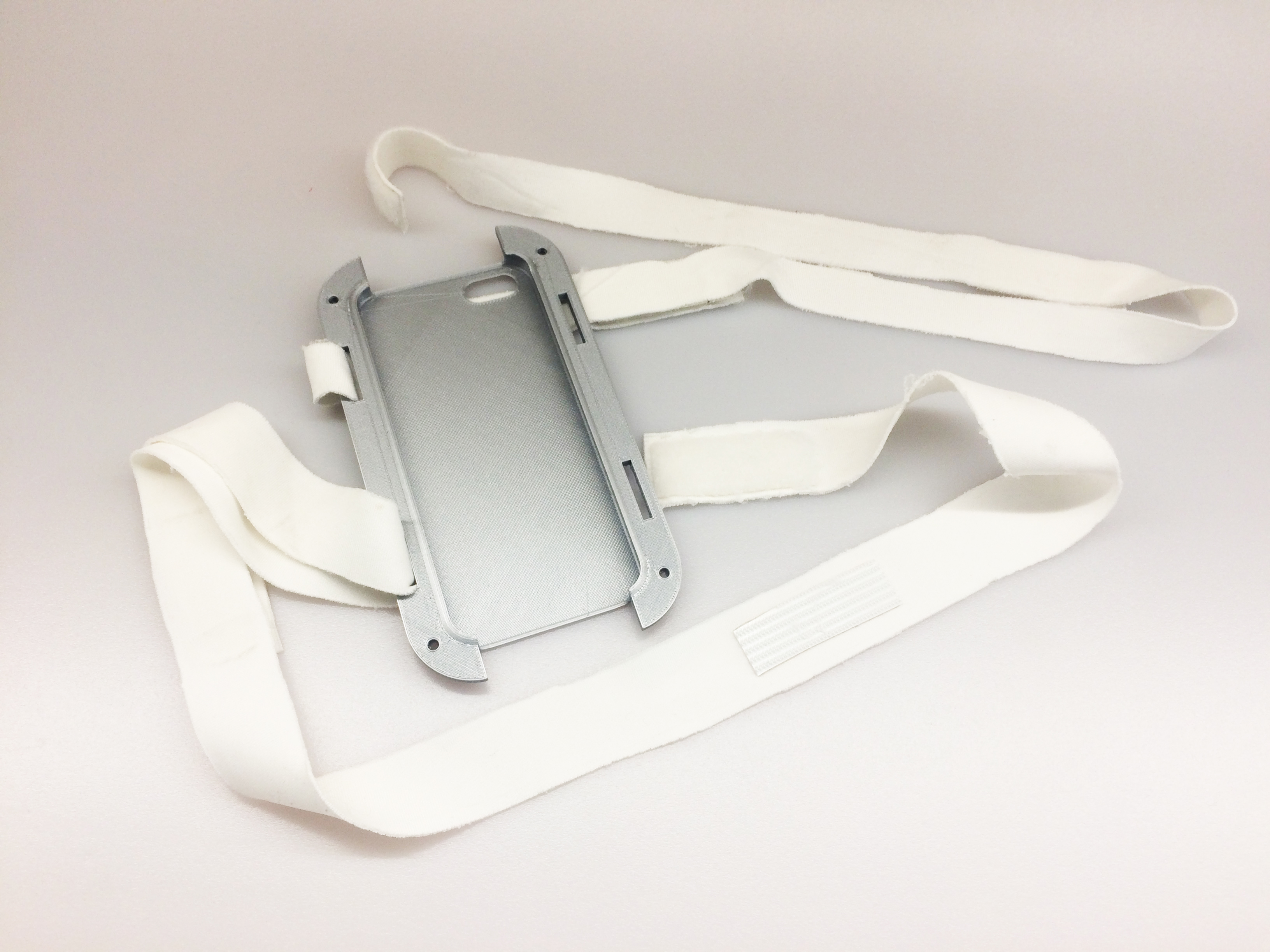
The project uses gyrOsc attached to custom designed iphone harness. By wearing this harness, user’s interaction is no longer limited to the hands, but instead the entire body has to be utilised to interact with the program.
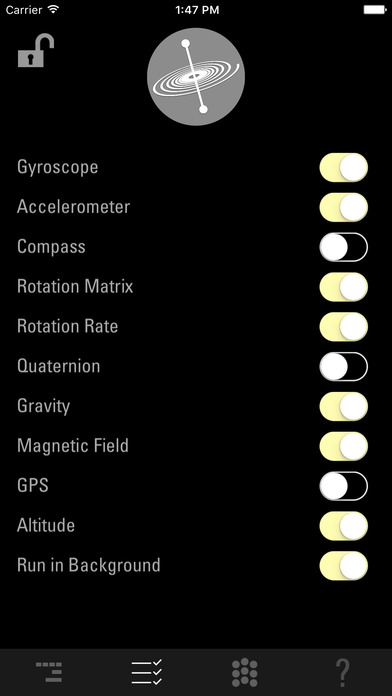
gyrOsc
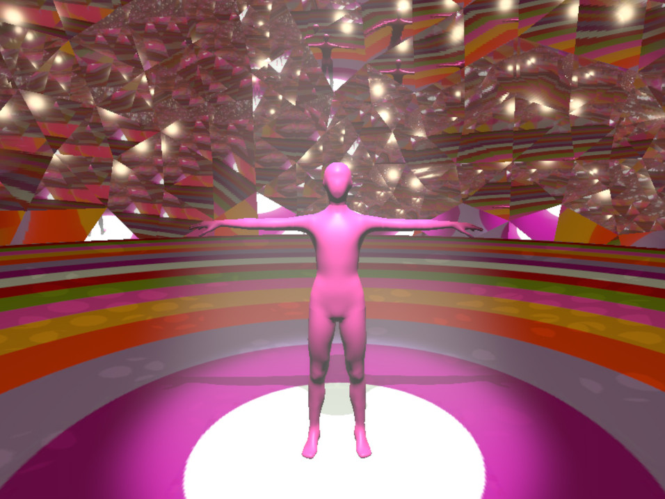
The project includes 5 different computational sense ‘Gyroscope’ , ‘Accelerator’ , ‘Optical flow’ , and ‘Gravity’. For each individual computed motions the user is expected to utilise their own body to counterbalance with computer motions. The user can observe the process on the screen as they act.
The aim of each ‘Act’ is to sustain the system until its reaches the ending point at which point it will store the final result of the ‘Act’ as a drawing, and a 3d mesh.
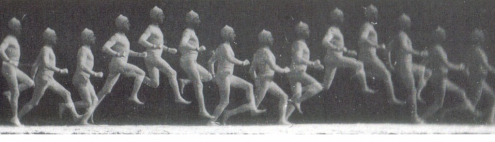
Therefore, a man himself become a drawing machine and the character of the sensors become an choreographic instruction and the final drawing produced can be analysed and seen as an choreographic score captured in time.
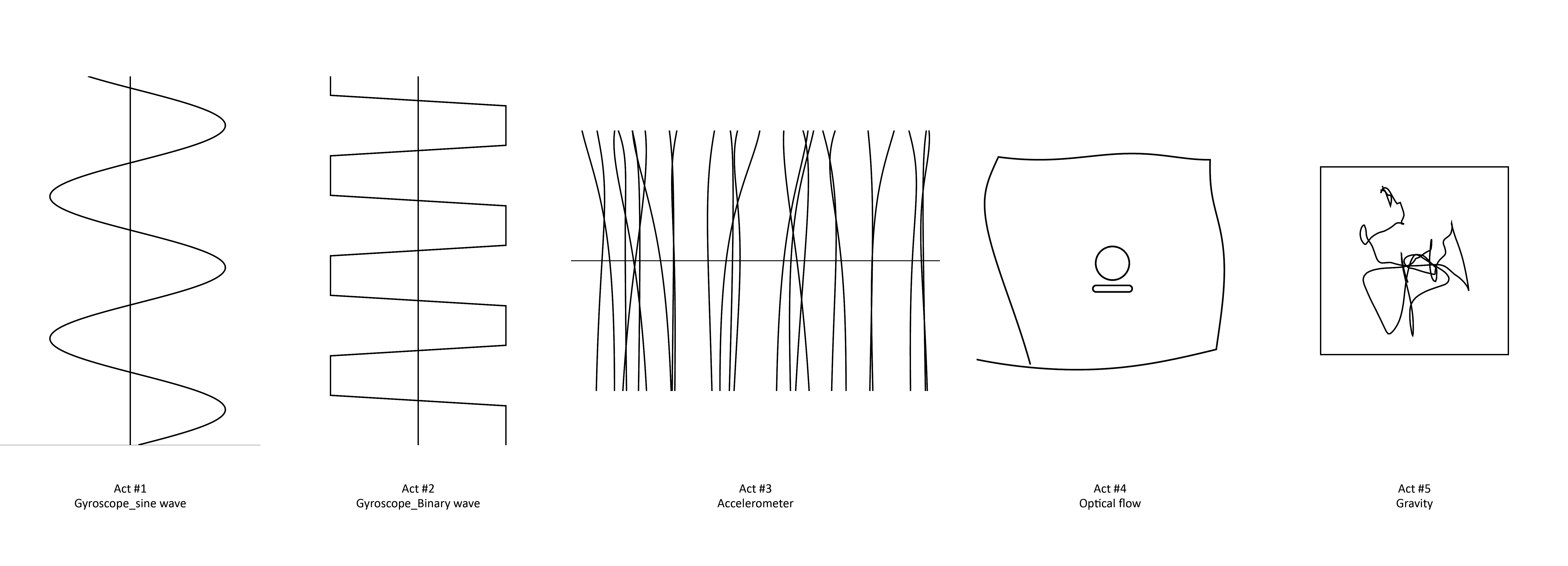
Computed Motions
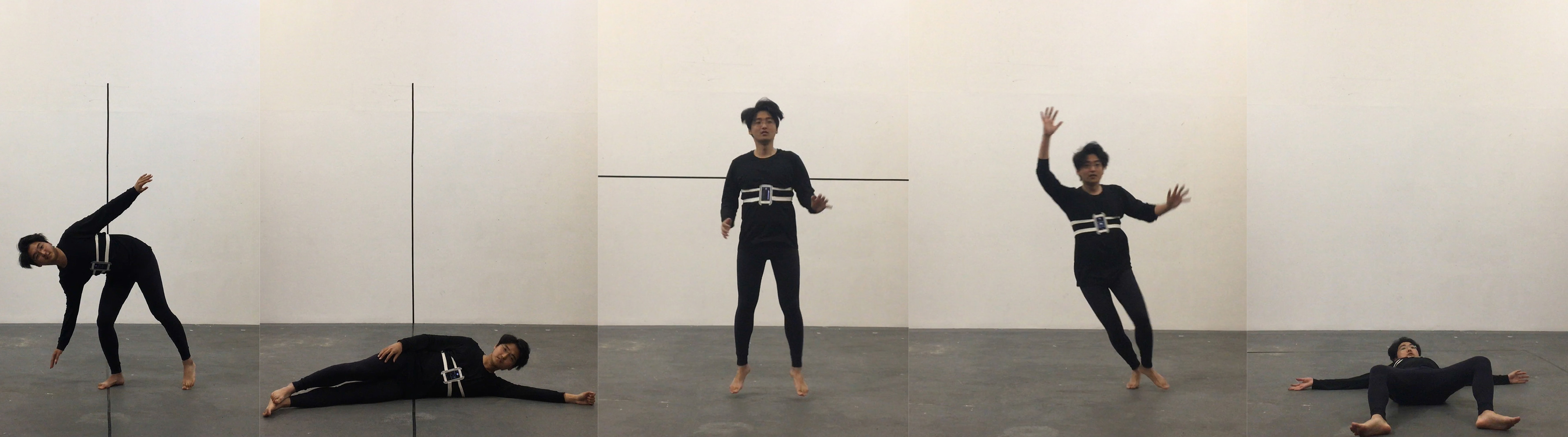
User's motion
For Act #1 and Act #2 the user has to try to keep the ‘moving agents’ and their trail as close to the centre line as possible.
For Act #3 the user has to accelerate himself to stop the ‘agents’ dropping outside the screen. Once the balls drop outside the window, the system clashes and saves the drawing. Therefore the dancer drawings are, longer the user has survived.
For Act #4 the ‘agents’ are trying to escape the screen and the user has to move in opposing direction to keep them inside the screen.
For Act #5 the user has to counterbalance himself as the movements of the agent are caused by the user’s own posture. Once the balls reach outside the box, system clashes and saves the trail of the movement as 3d mesh.
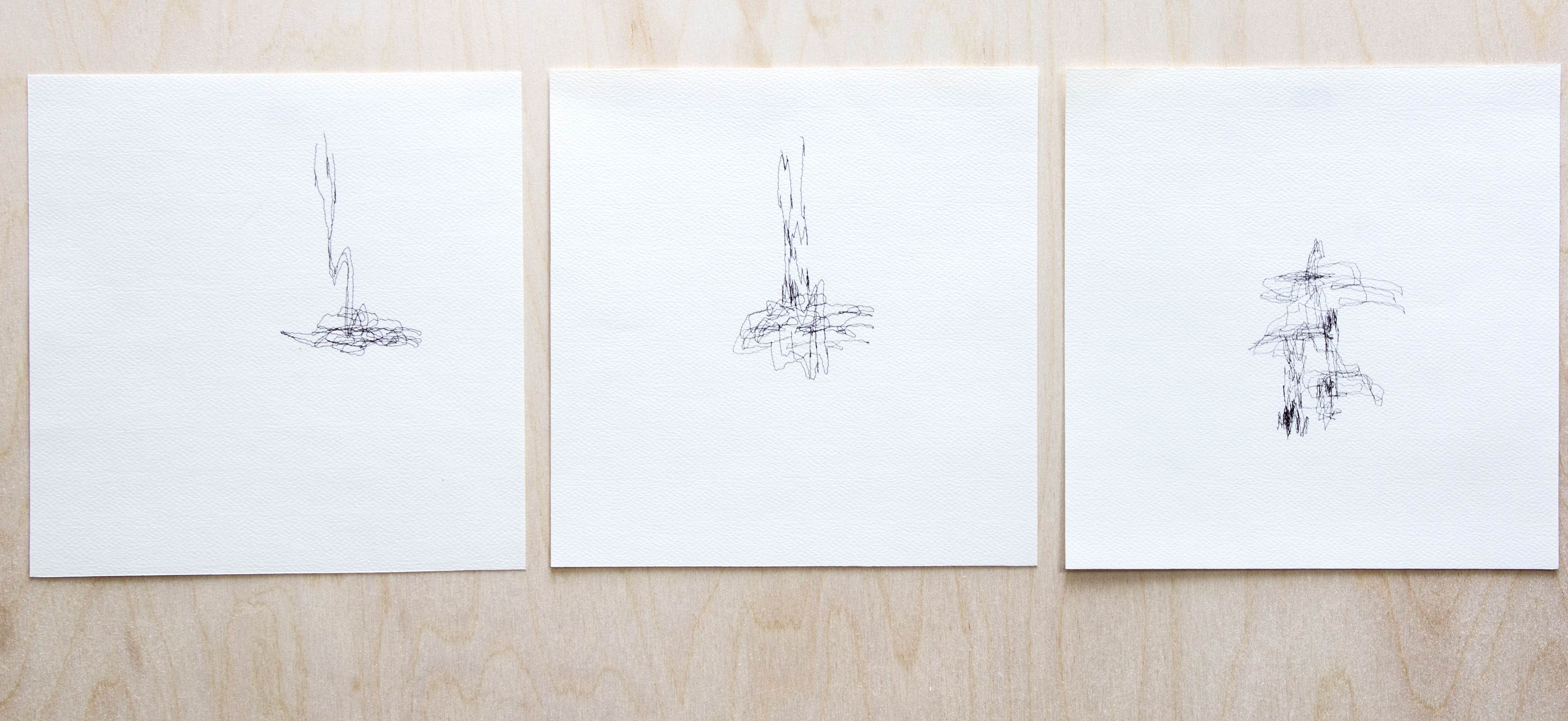
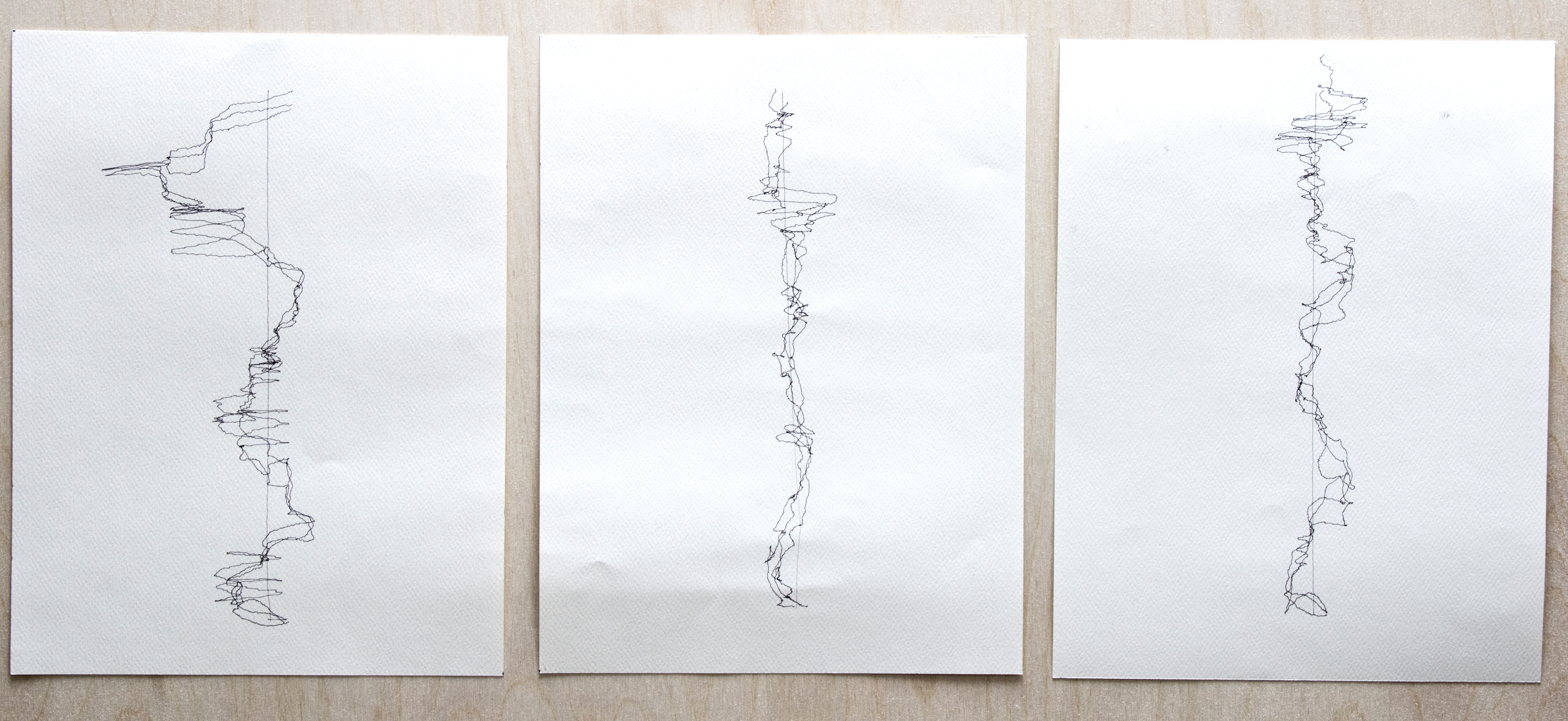
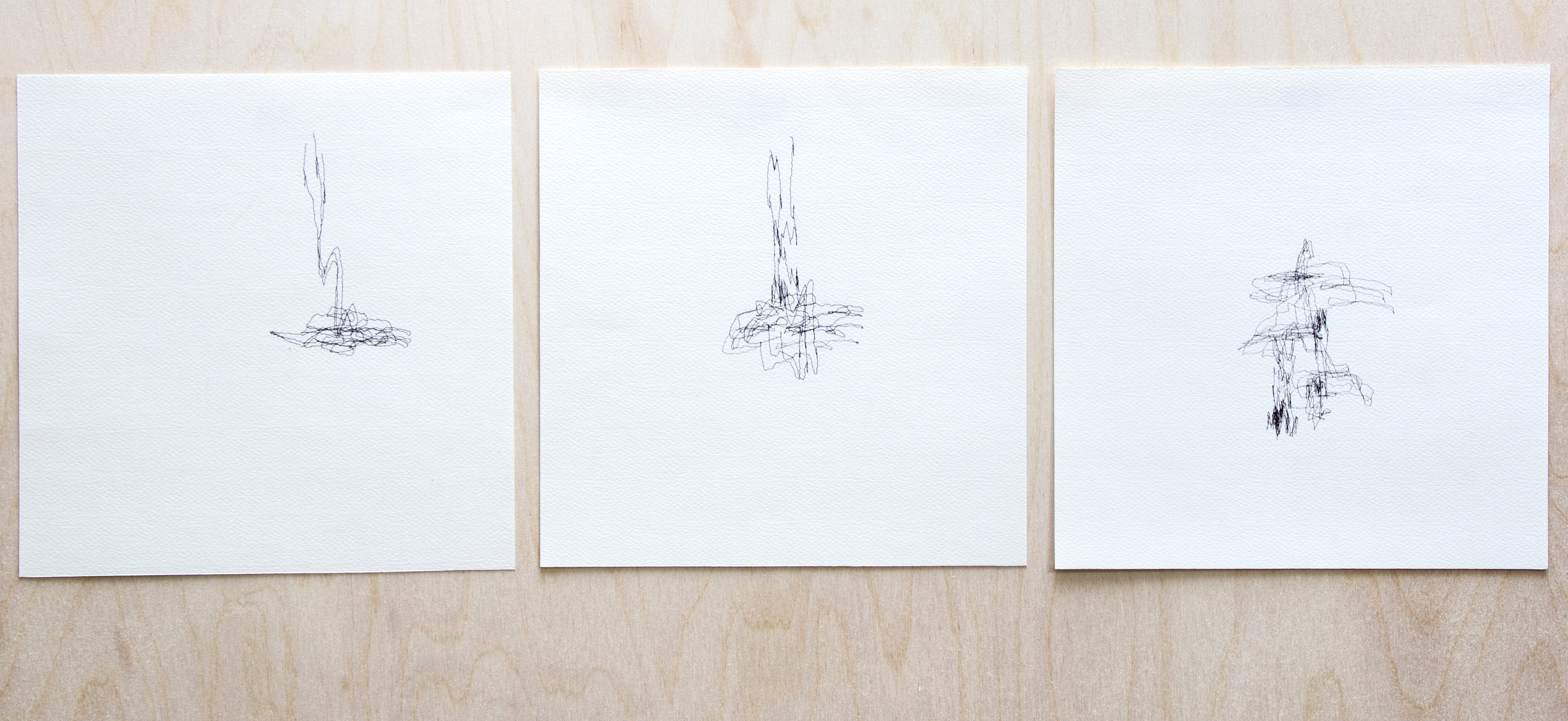
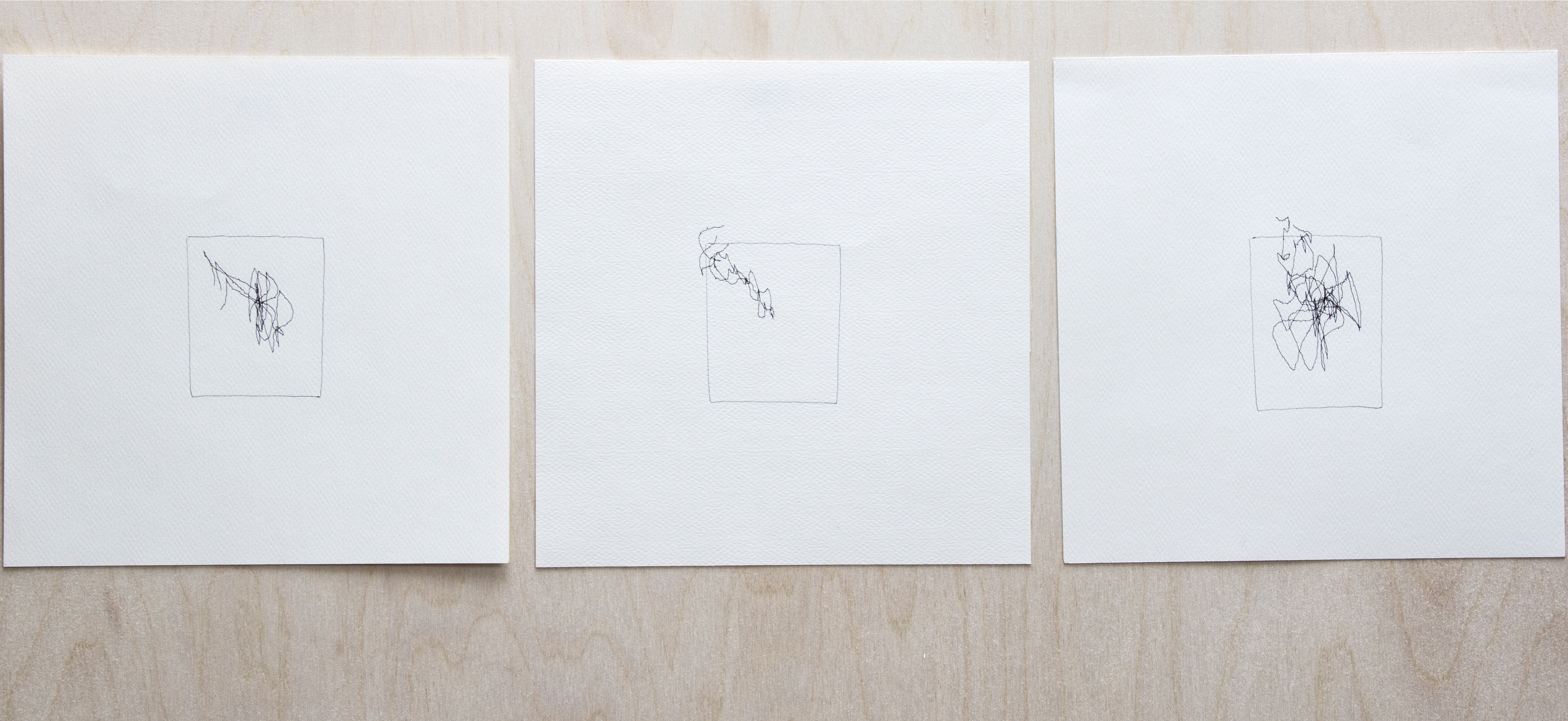
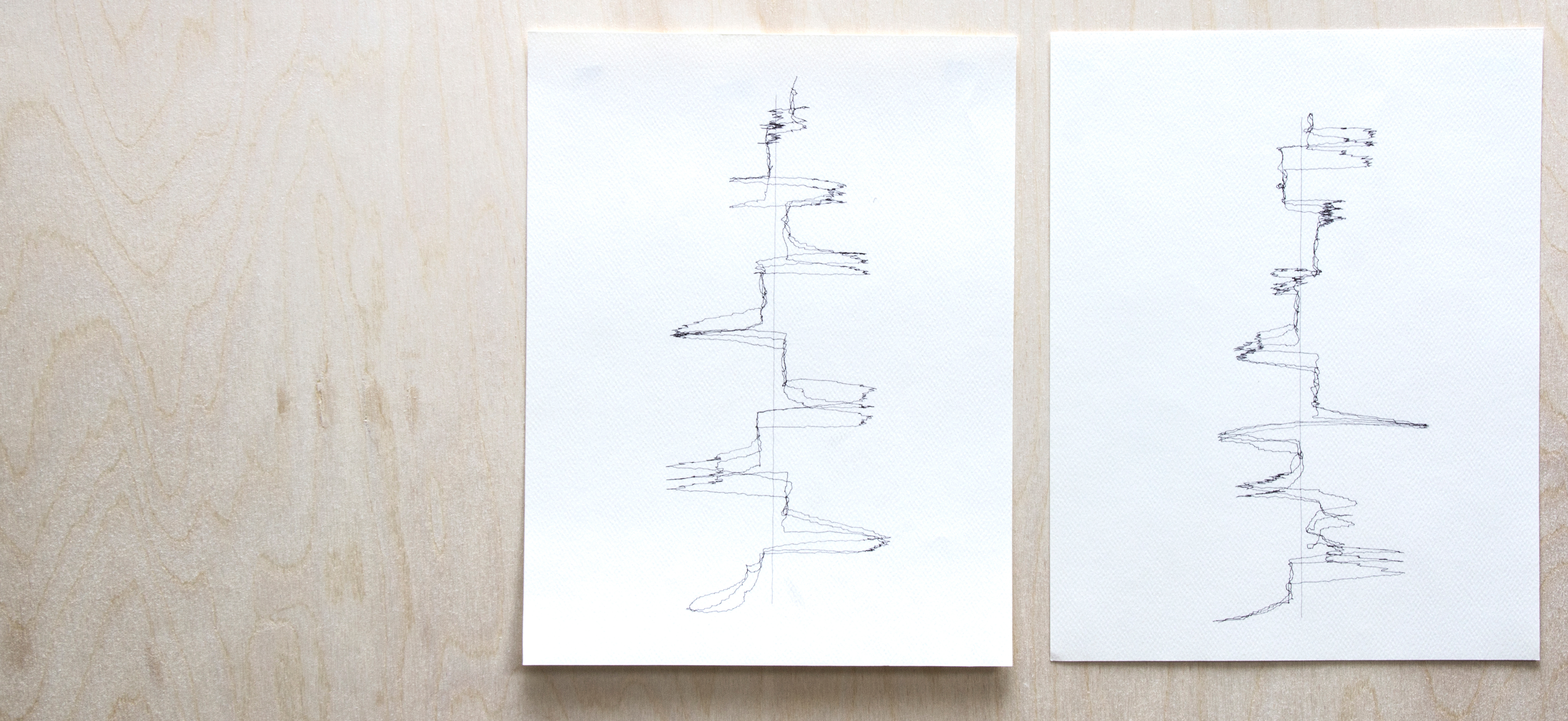
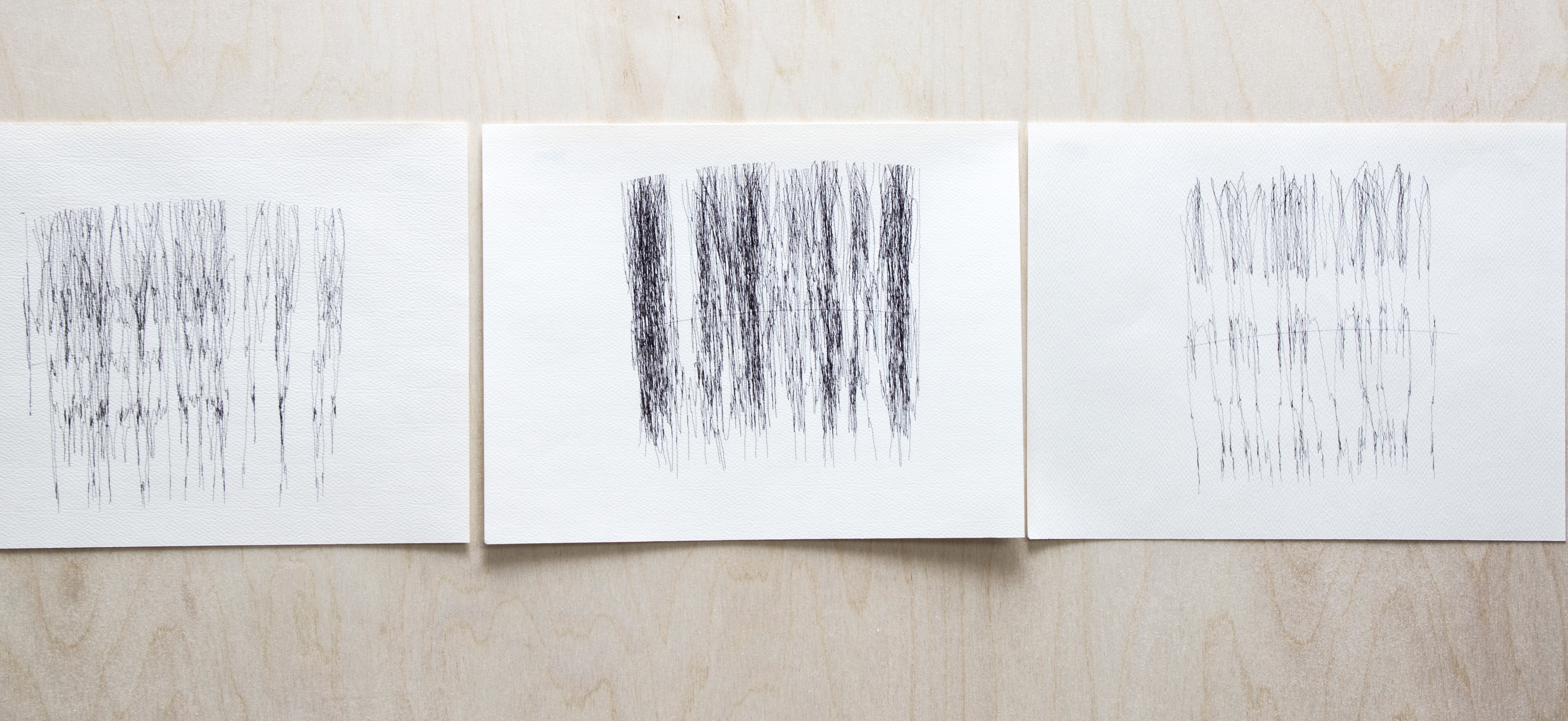
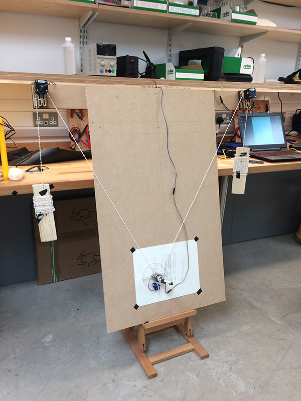
The Actual Vertical plotted drawings
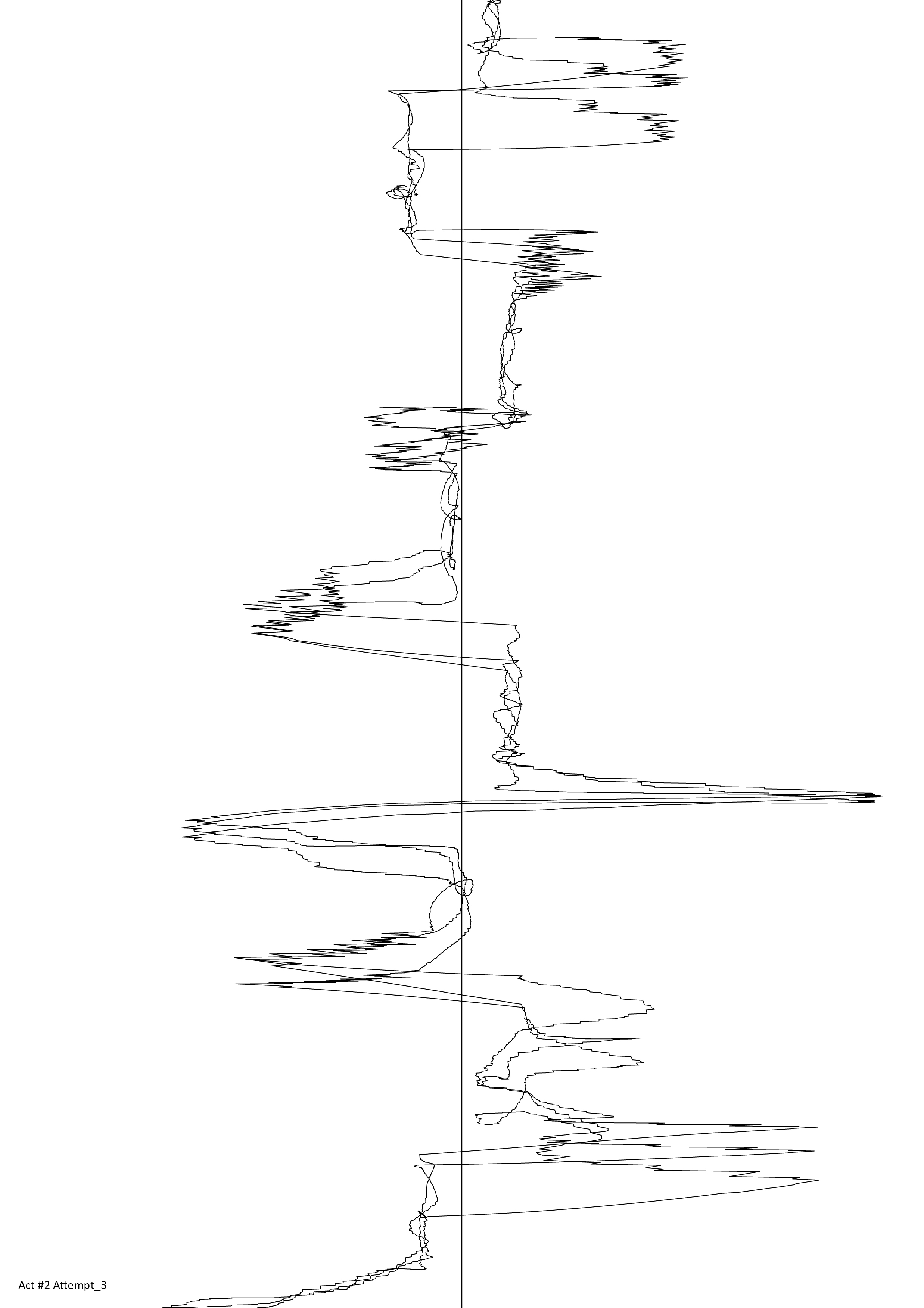
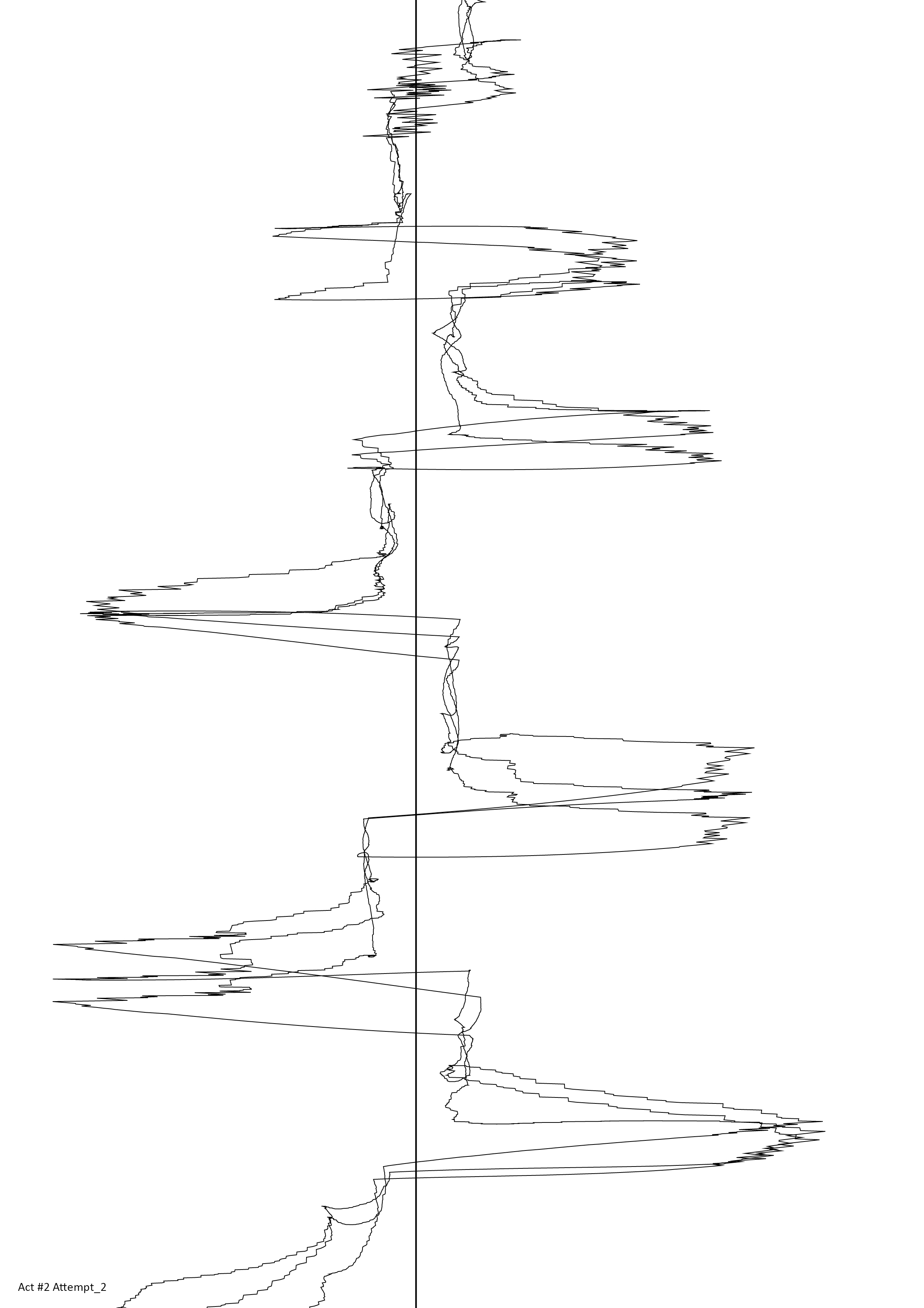
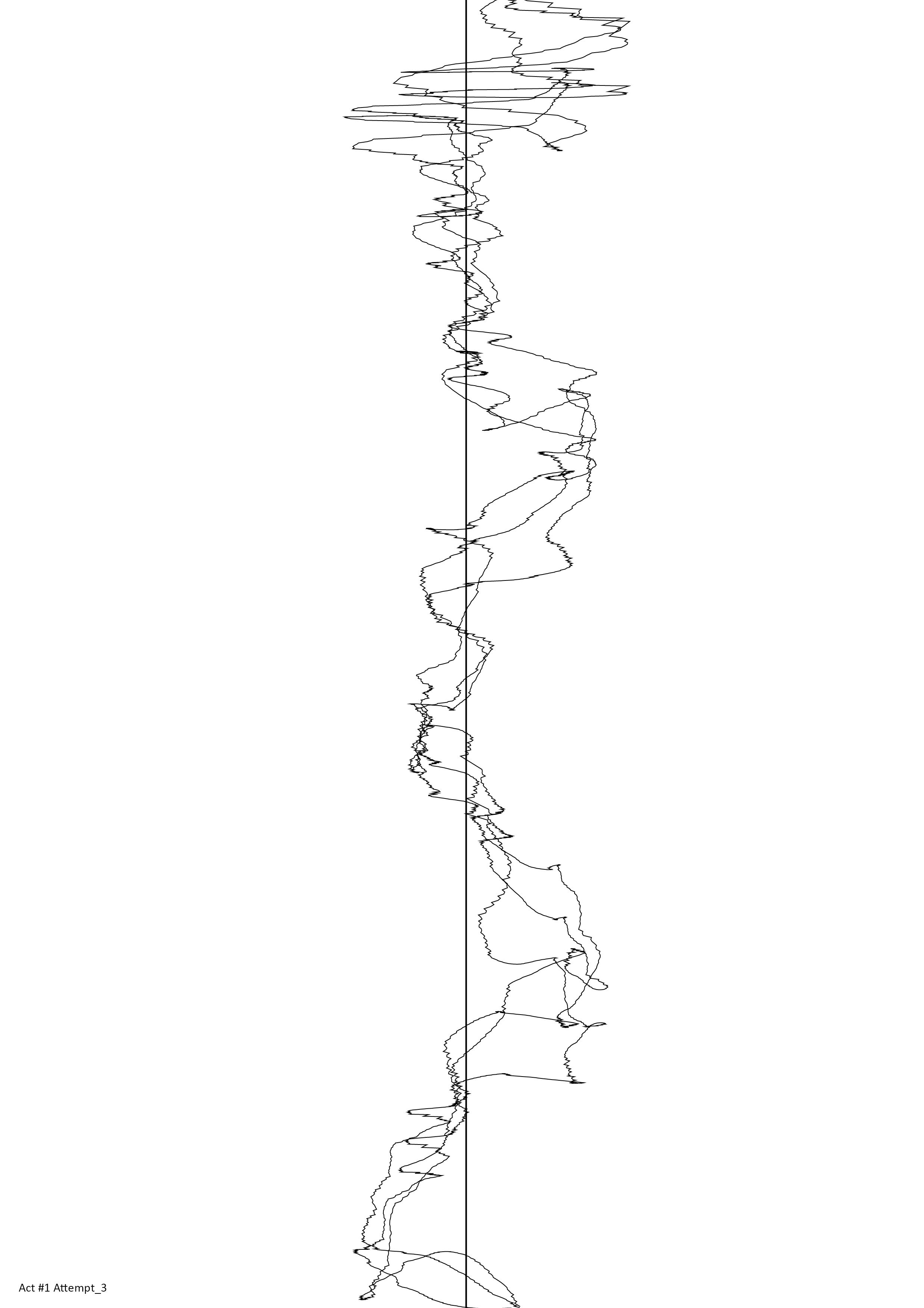
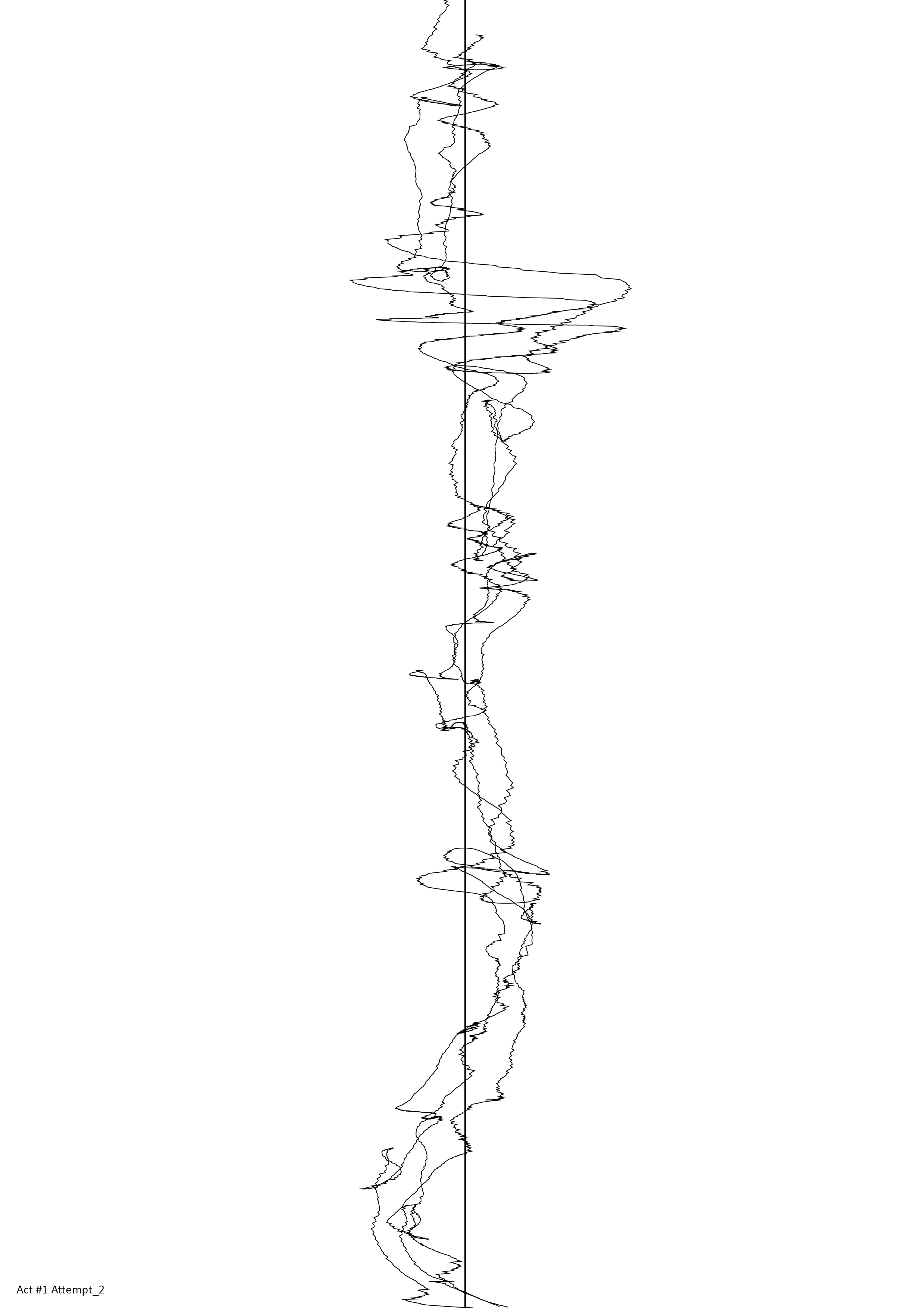
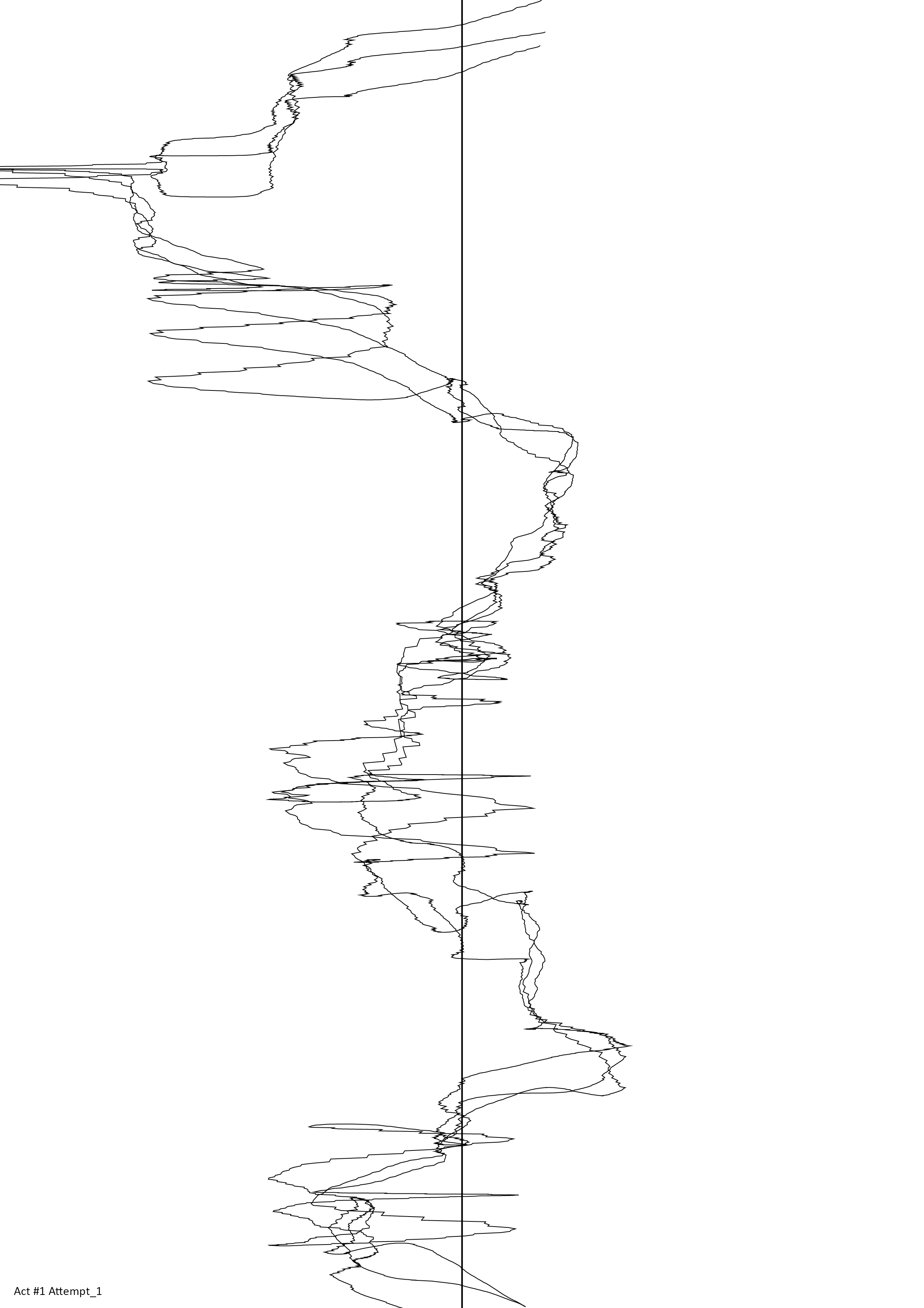
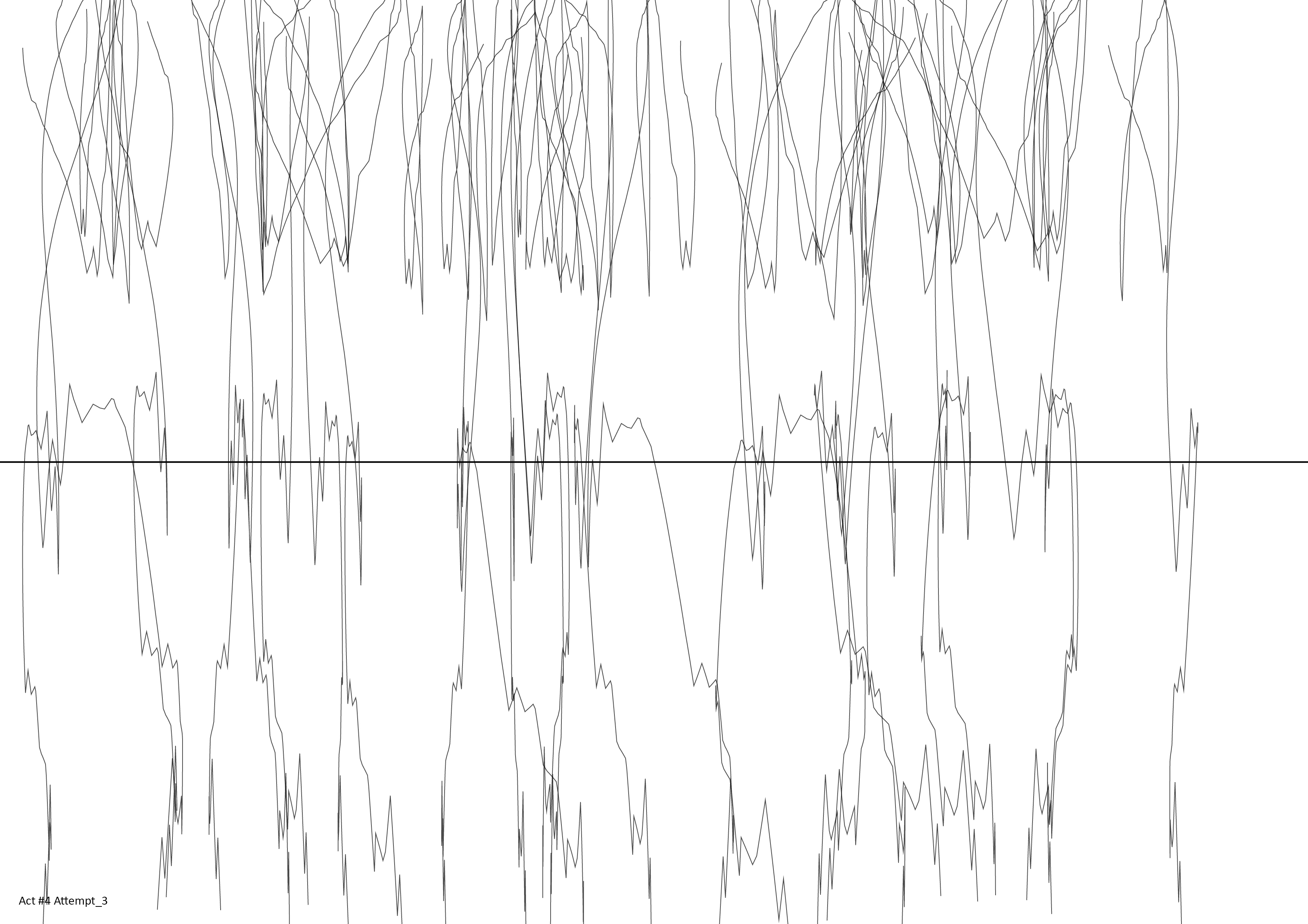
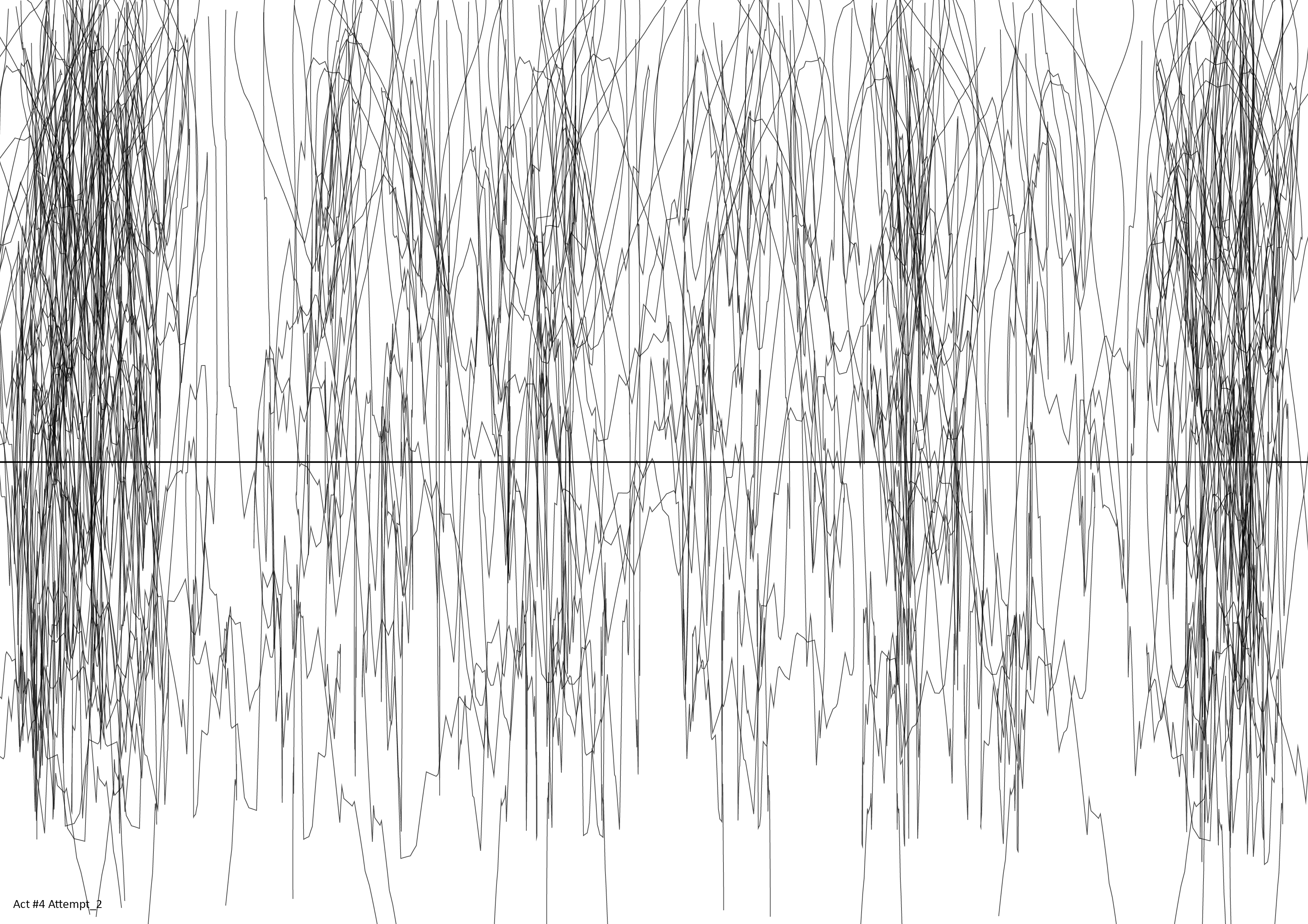
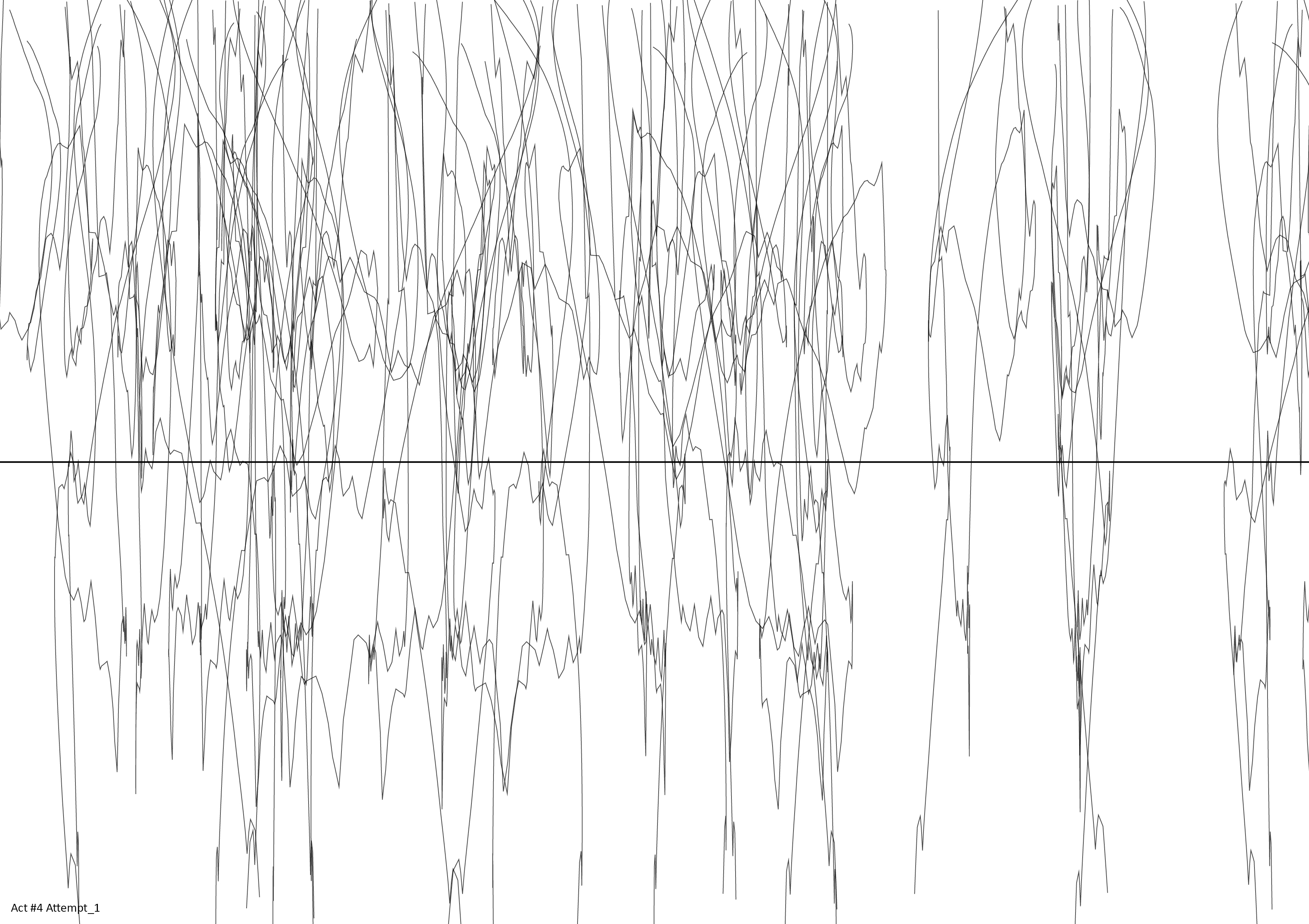
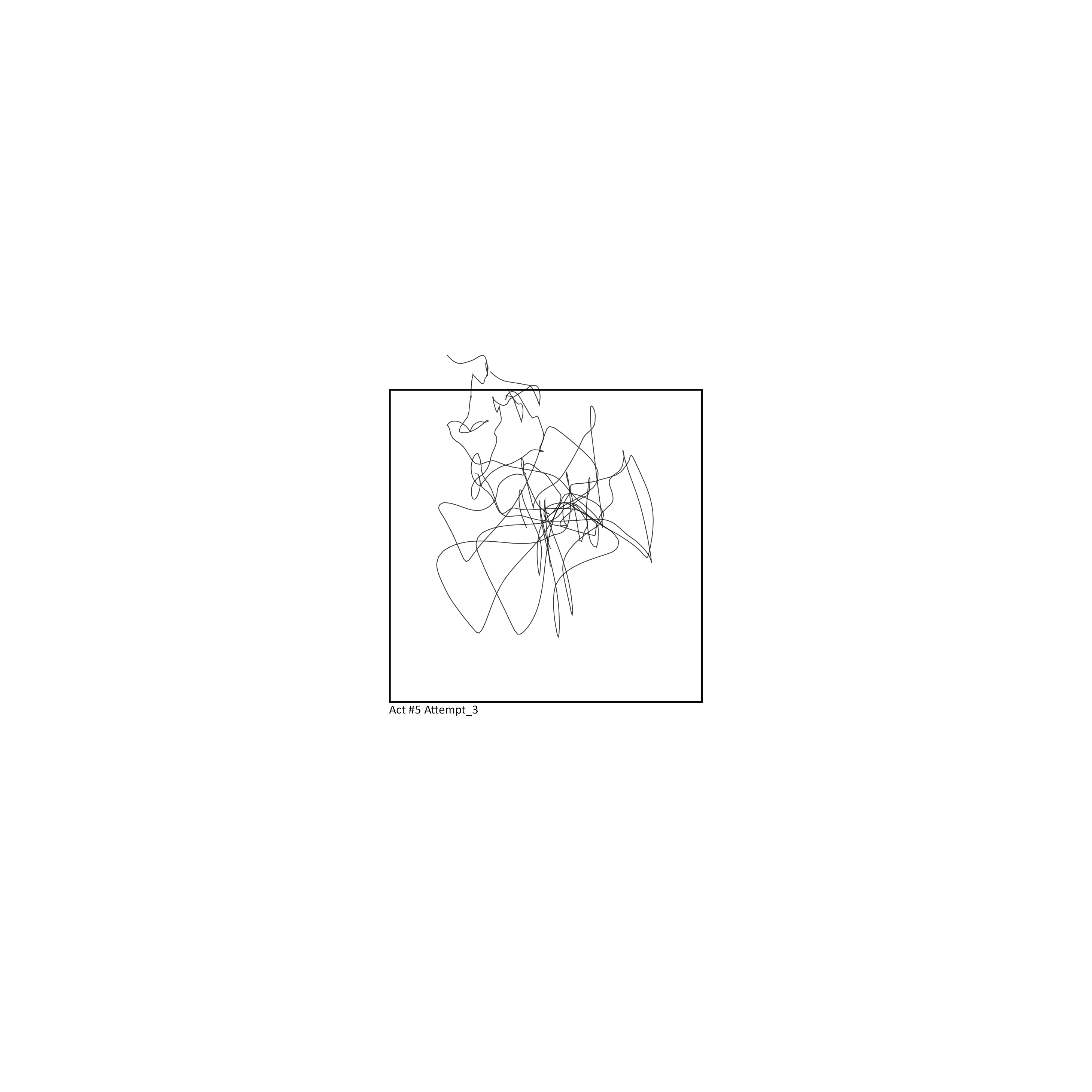
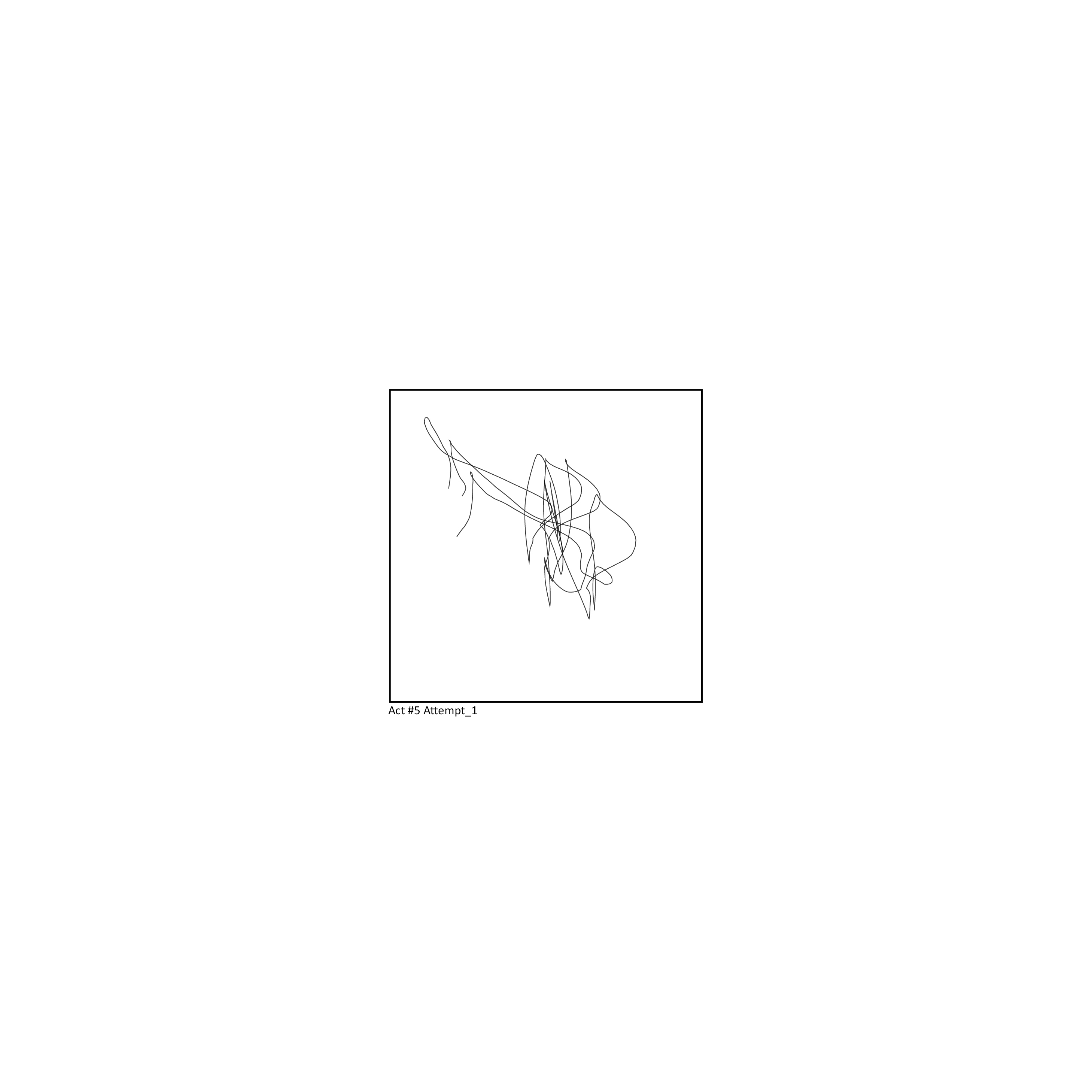
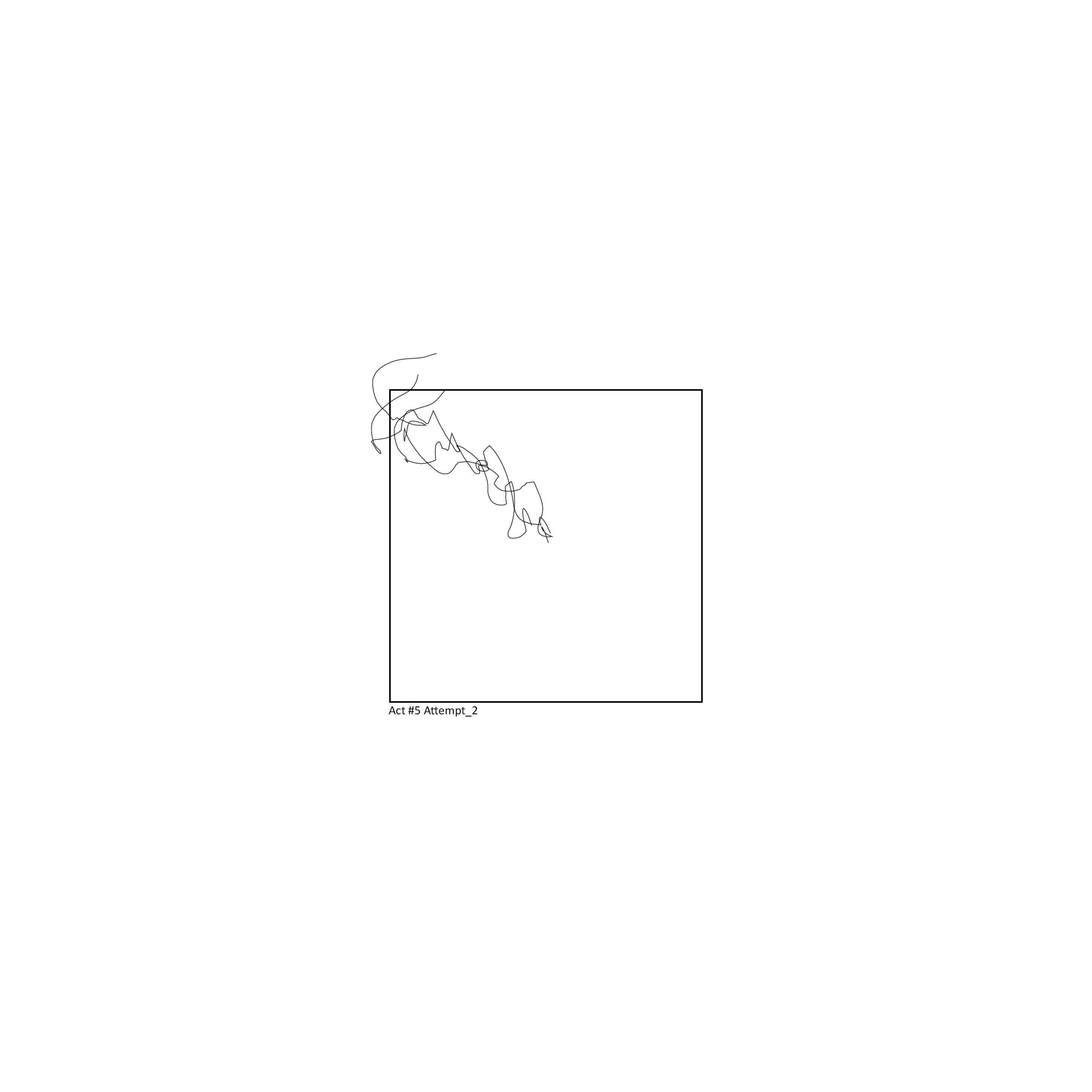
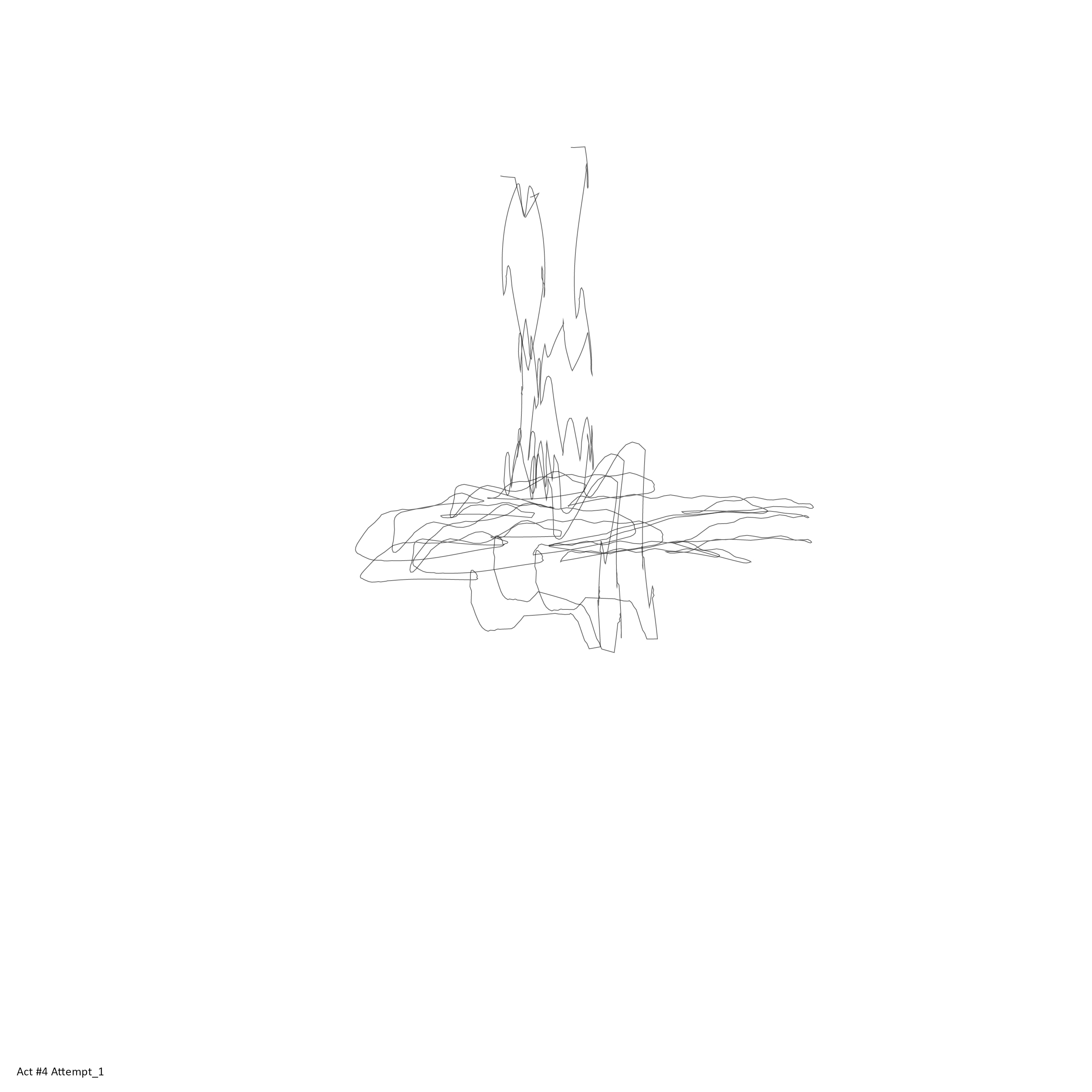
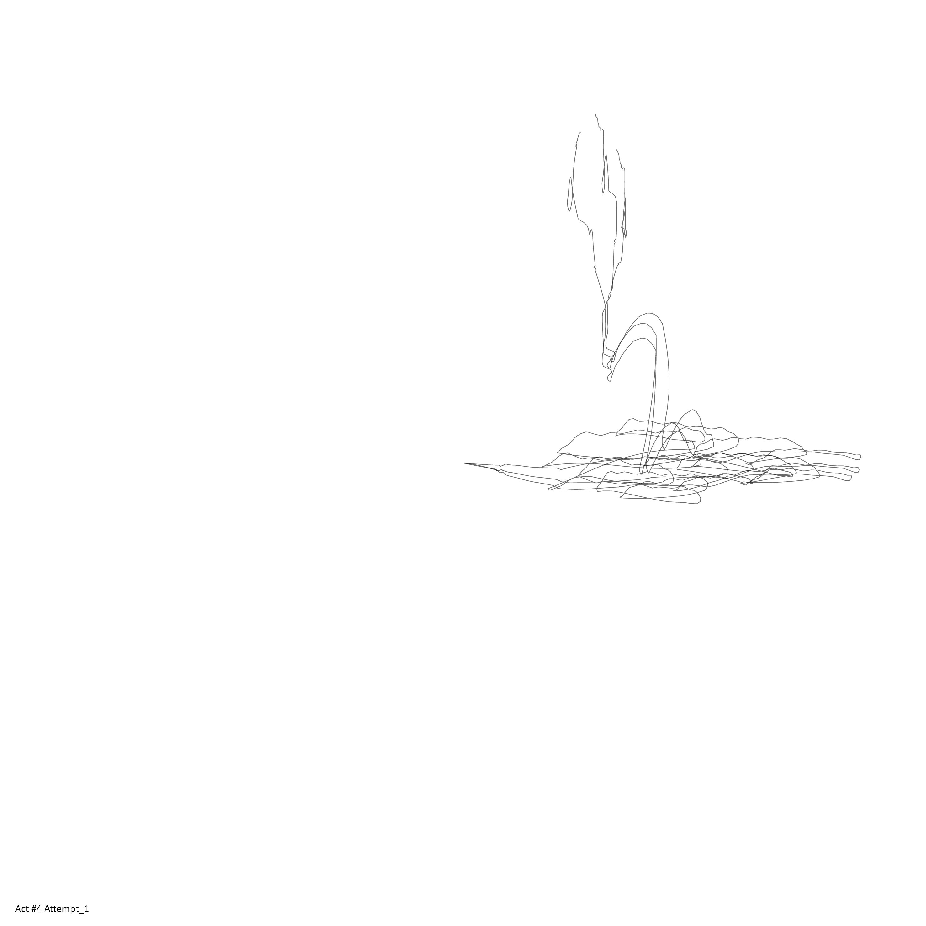
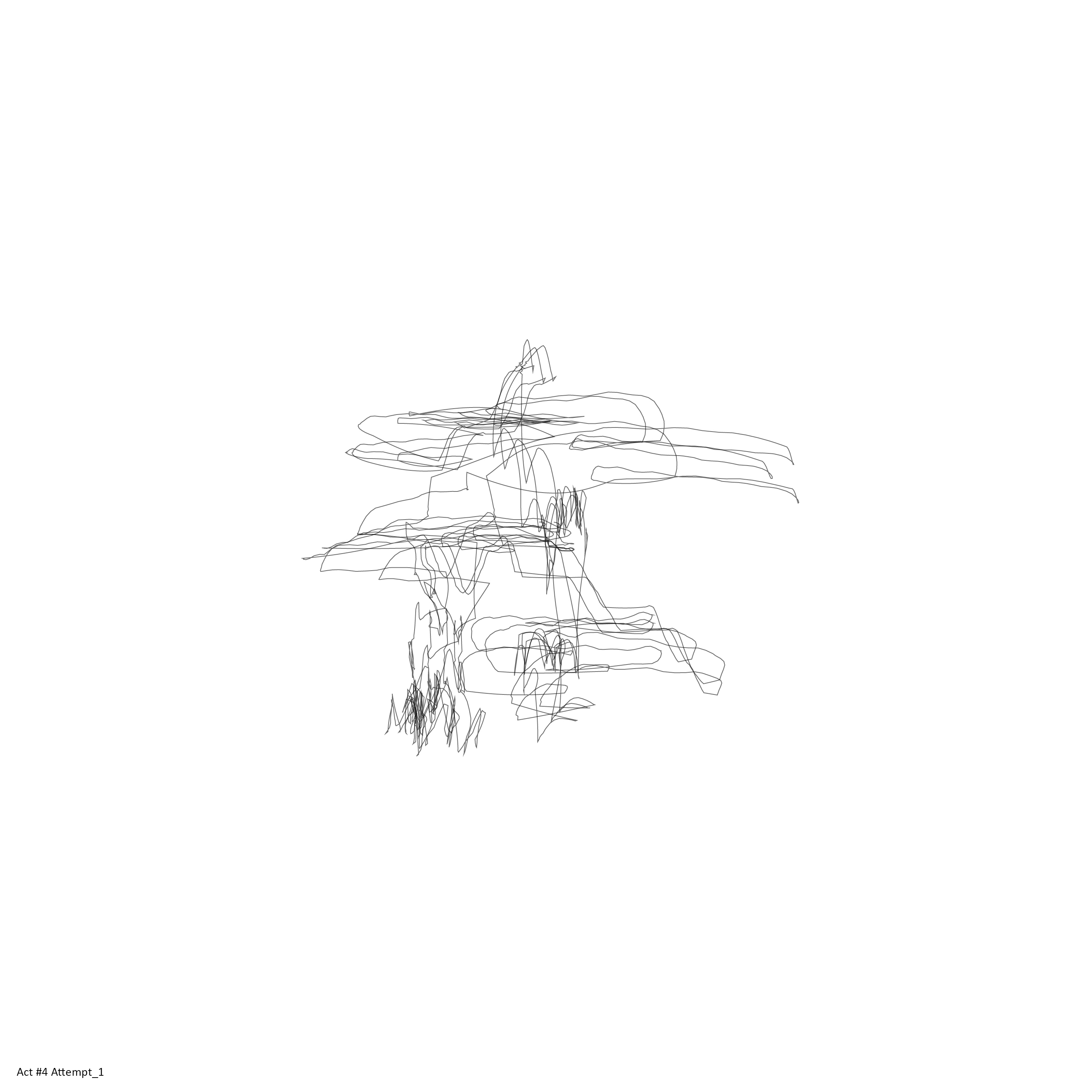
All the attempts exported as a vector drawing
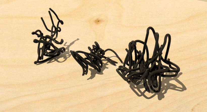
3d prints of the ‘Act 5’
The project takes the advantage of the vector images, and demonstrates the conversion of my physical movement into computational language by introducing ‘vertical plotter’ and 3d printer to physically draw the final outcomes of each ‘Act’.
Printing of the Wire-frame structure was able on FDM printer, by using water soluble PVA support.
Further Development
Possible further development will include multiple users interacting with pavilion or an architectural space, through sensors.
Reference
Oscar Schlemmer
Rebecca Horn
Polargraph (vertical plotter) - http://www.polargraph.co.uk/
Spline Interpolation
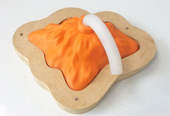
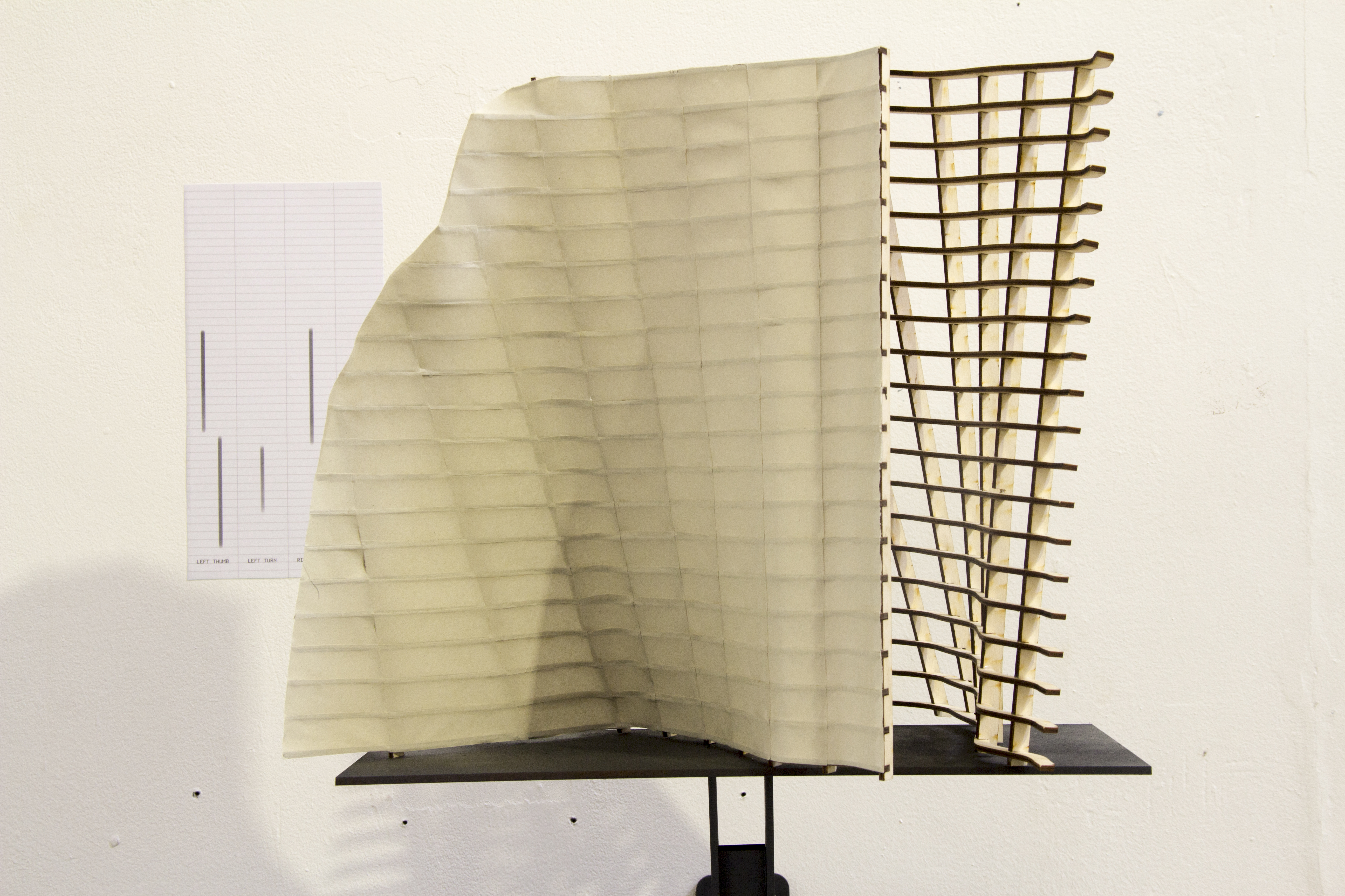
Spline and other forms of curve calculation such as beizer have become the core function of computer CAD. This project reference to our spine structure to create an origami sculpture that at each joint has a capability to move and reform its shape.
This program has a very basic interface. The user by pressing a mouse, add a control points between pre-existing straight line. This is a fundamental method of drawing a curve, or polygonal lines on computer CAD. Through representing this process on the physical object. I wanted to re-emphasise this very basic method or a process of drawing objects on computer. Therefore for this microscopic scale, I wanted to work slightly in a different manner where instead of the computer program imposing a shape of the accordant physical artefact, the program itself manifests inside the physical artefact.
For the last scale, I wanted to show an algorithmic method of constructing an object in an analogue process. Therefore the project aims to show that the computational design does not necessarily require computers in order to be achieved.
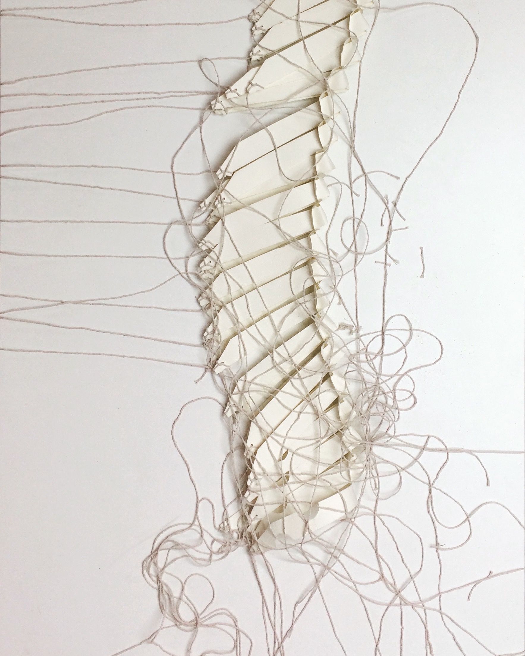
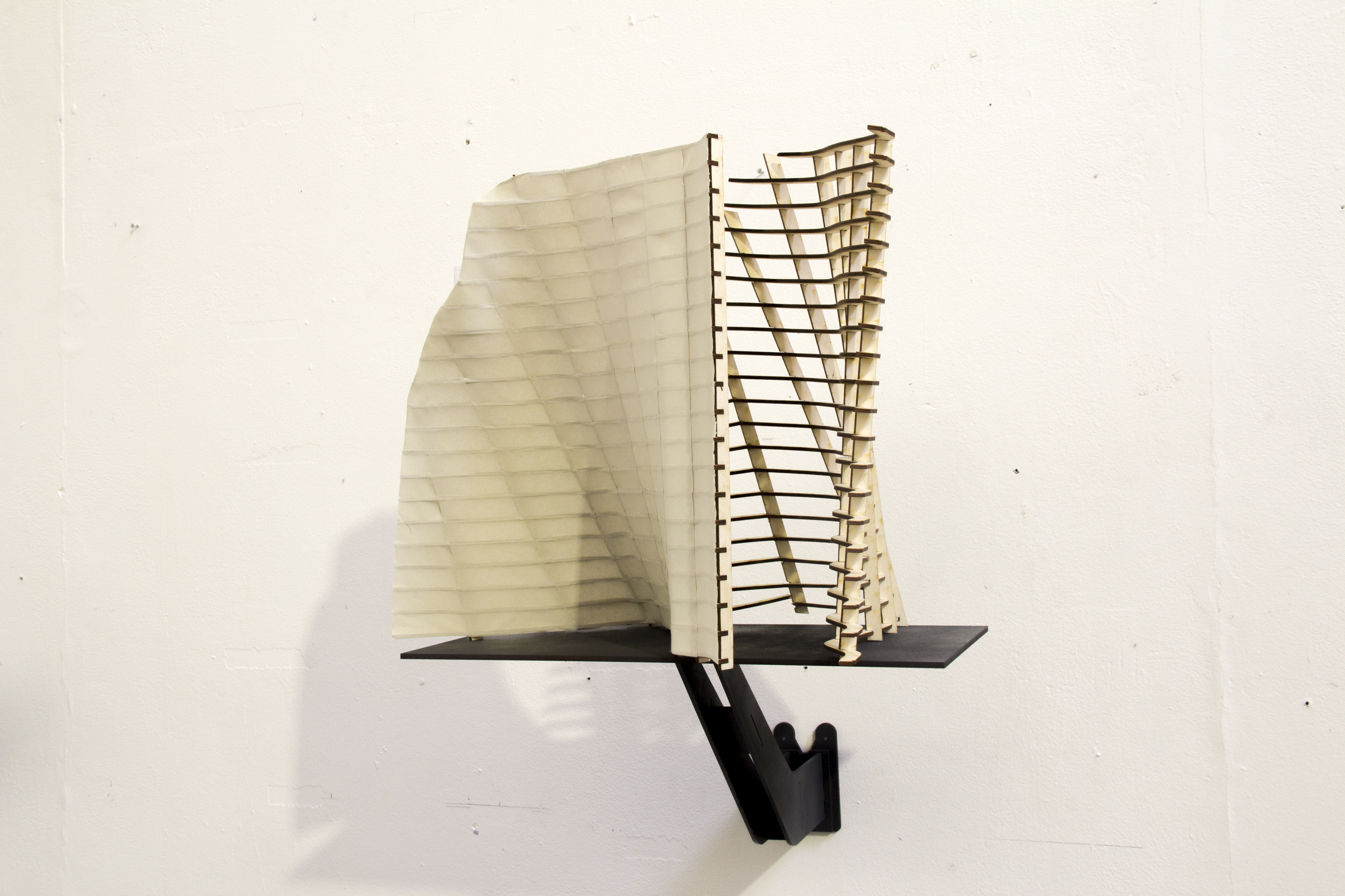
spline interpolation as a physical artefact
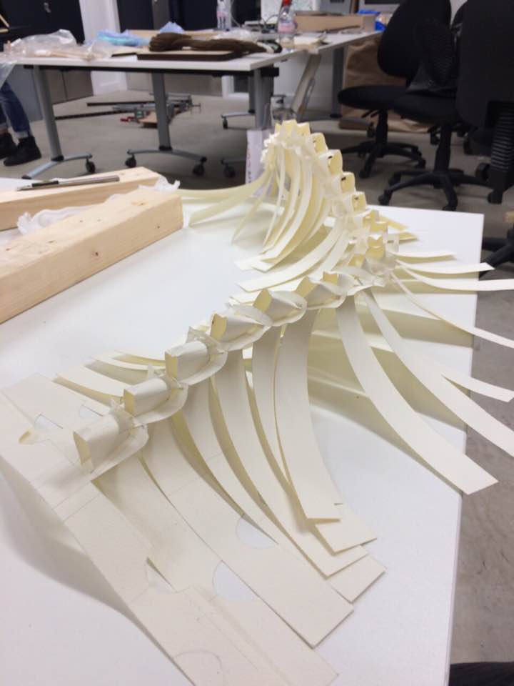
This spine structure consists of 25 individual paper folds that are connected to each other through interlocking repetition with no aid of glue or other means of connection. Therefore each point where the folds interlocks becomes a control point or a 'joint' just like our actual spine.
Each paper folds has a wing that gets knotted with a string that later connected to a laminated timber for a manual control of the location (vertex) of each control point.
Very careful attention was given to this detail, as computationally this interlocking system was repetidely used and as a whole has big impact on how the structure is shaped and viewed.
Each wings of the paper fold, had a string knotted to it in a very careful manner again without using any glue, but purely through a mannual method.
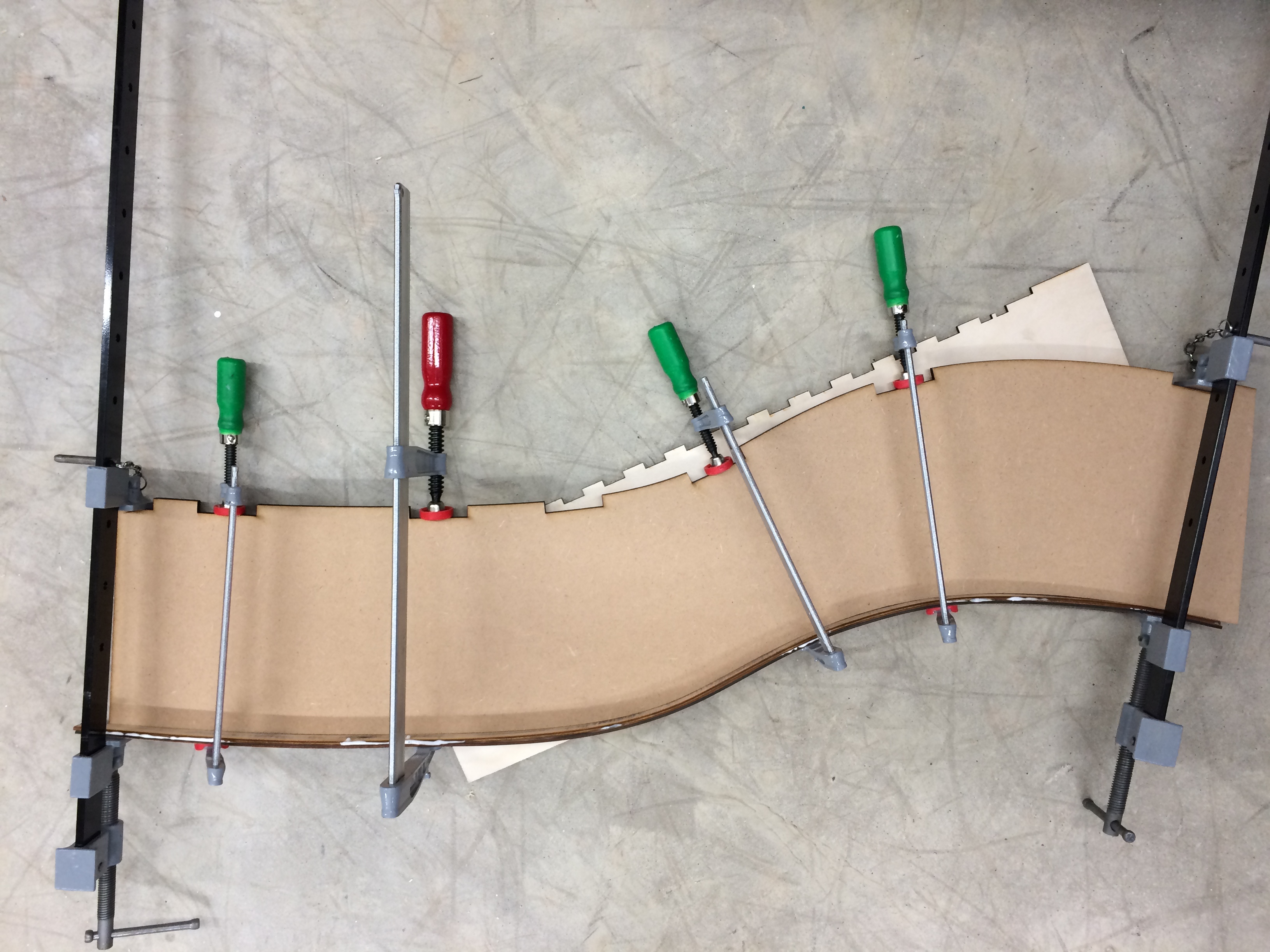
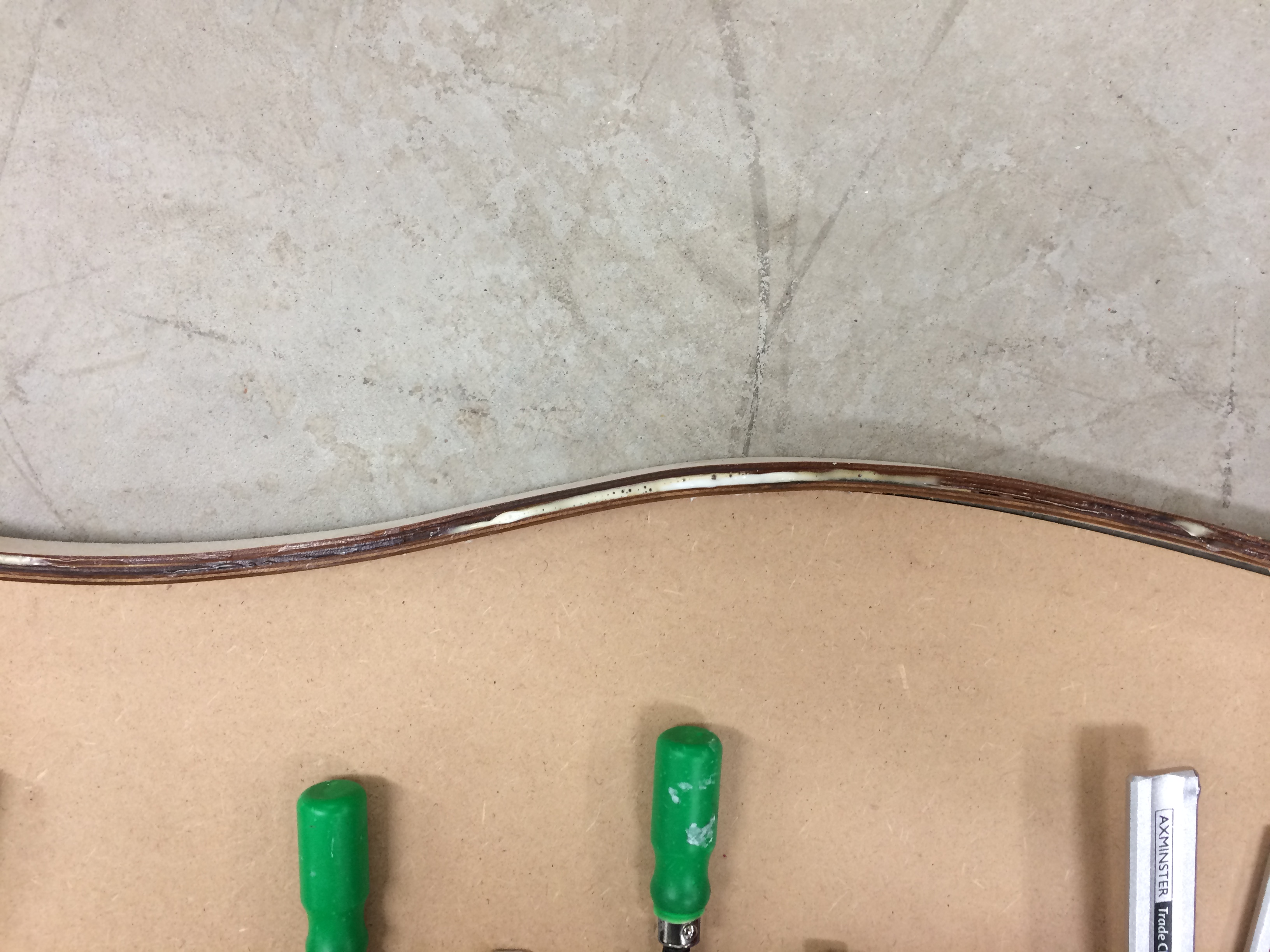
timber lamination
Paper folds are connected to the laminated timbers that already has a curvatures on it. The two laminated timber had a slightly offset curvatures and this way the spine structure could align more effectively. I have enjoyed creating connections and fold in an inventive way.
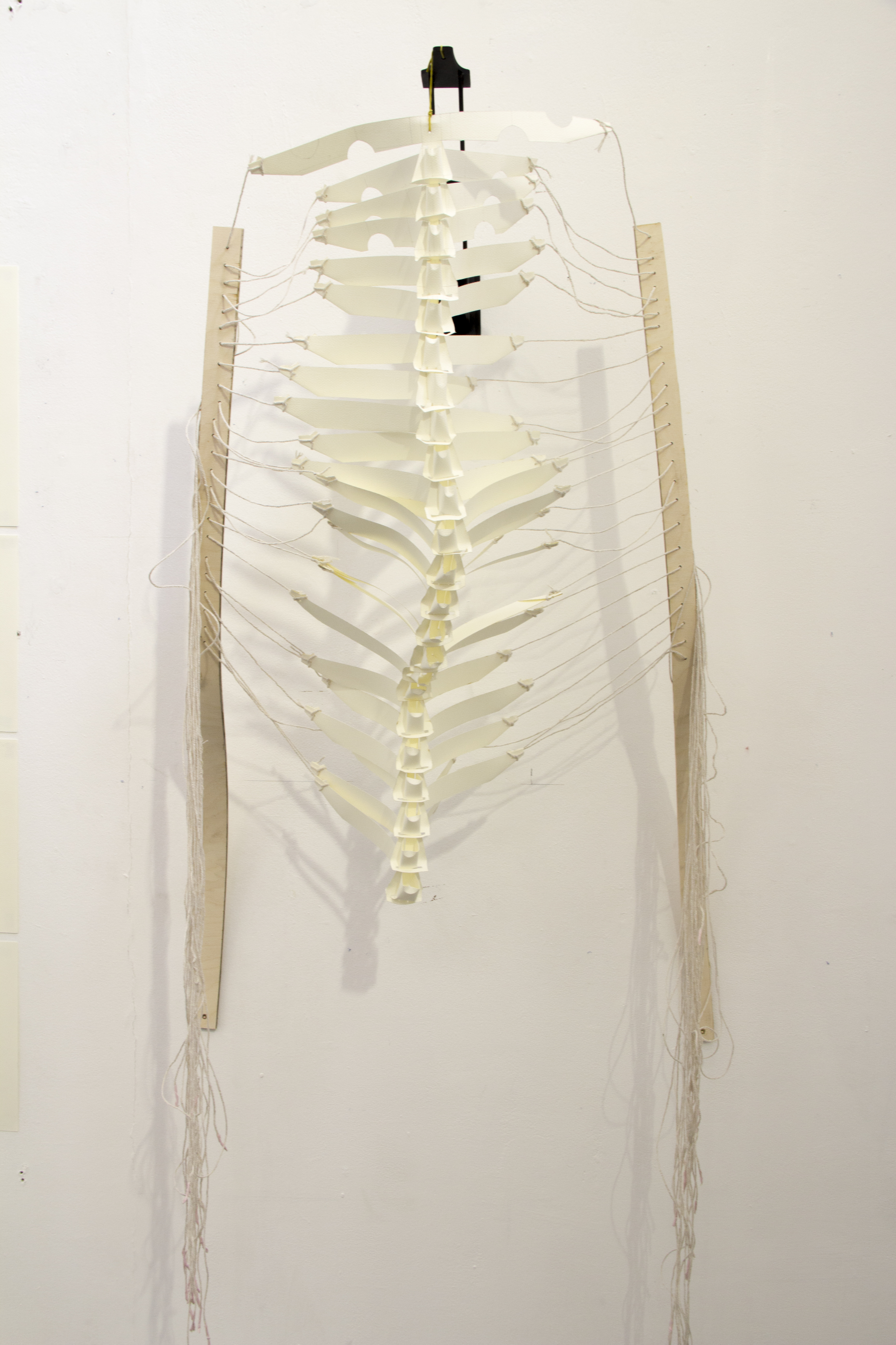
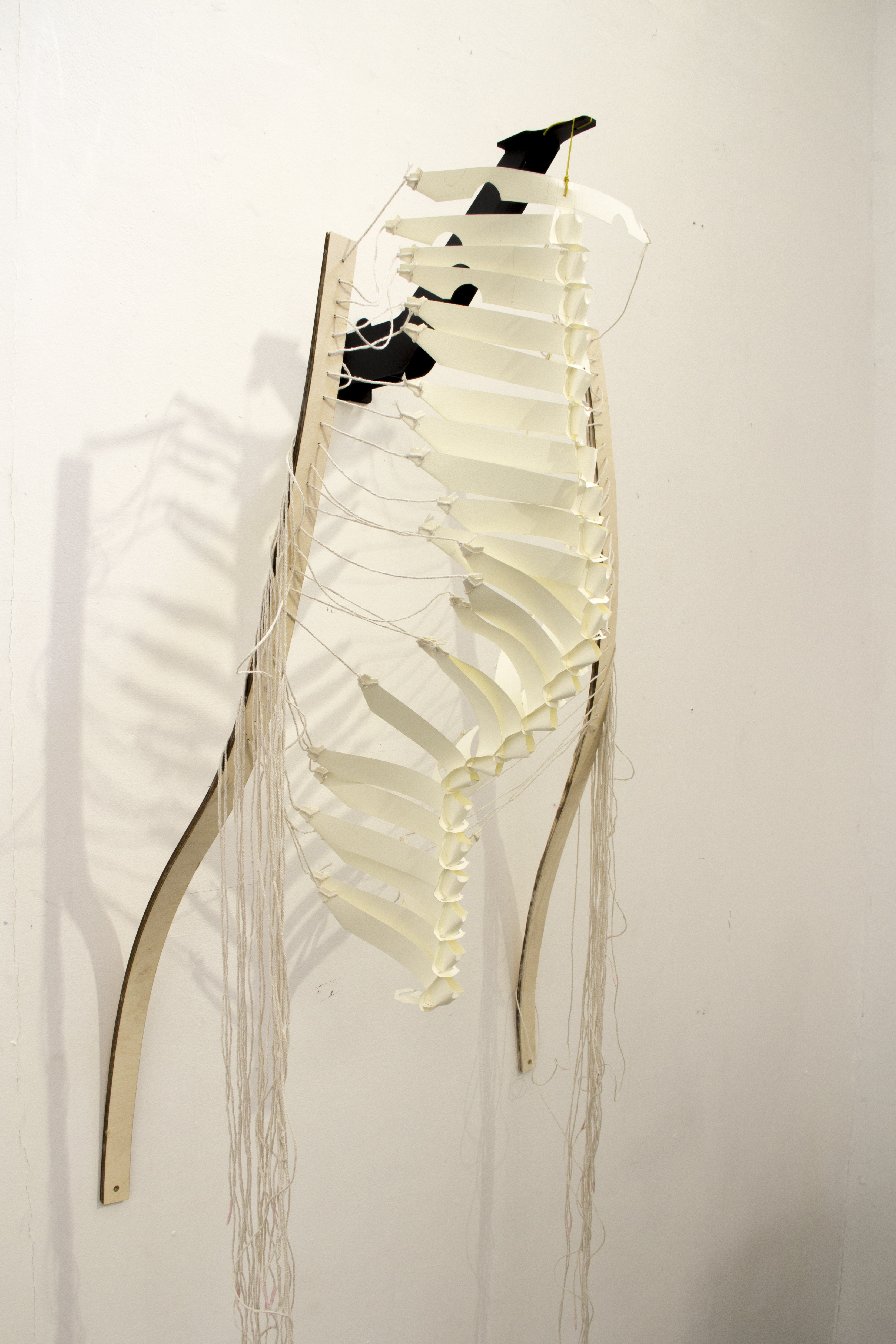
final shape
Shape of the spine can be altered by pulling a string that corresponds to the target control point. This way the spine can reshape in a very dramatic shape but still incontact.