


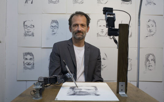


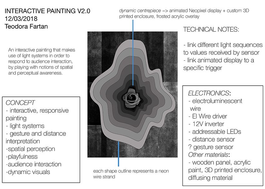
Interactive Light Painting
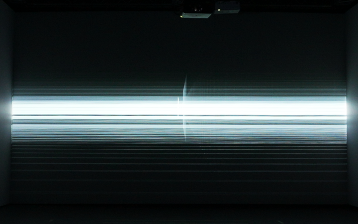
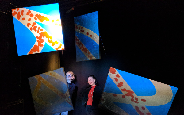
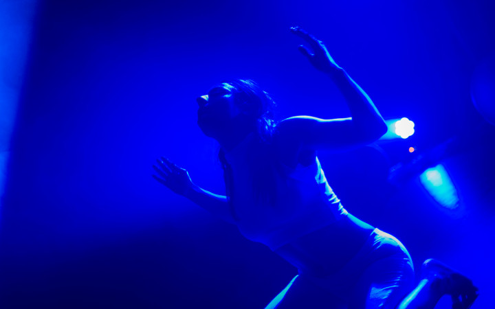
‘Echo Light’ is an interactive visual piece that explores addressable light applications in the field of painting. Relying on distance and gestural input, its aim is to create a dynamic visual display that changes in accordance to how the viewer interacts with it, while also playing with notions of perception and the way in which light can help create the illusion of space.
produced by: Teodora Fartan
CONCEPT
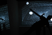
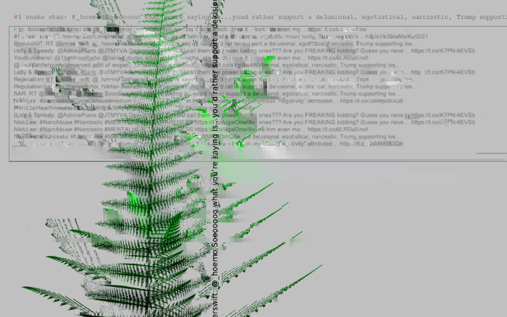
Originally inspired by Plato’s ‘Allegory of the Cave’, this artwork seeks to explore the politics of the real in the contemporary context and the increasing intervention of the virtual into our everyday lives. In the Myth of the Cave, Plato presents the reader with an allegorical tale in which individuals find it difficult to discern between appearance and reality, as often times what is presented to someone may in fact be an illusion. This age-old theory can be recycled and re-applied in the context of today’s proliferation of technological means that have immense capabilities of pushing against the edges of the real – in a similar fashion to those trapped in the cave, able to see only the shadows of a world projected on the wall in front of them, today the shadows can be reinterpreted through the lens of the digital, a medium which allows for the unpresentable to become present, shining through screens, lenses and headsets.
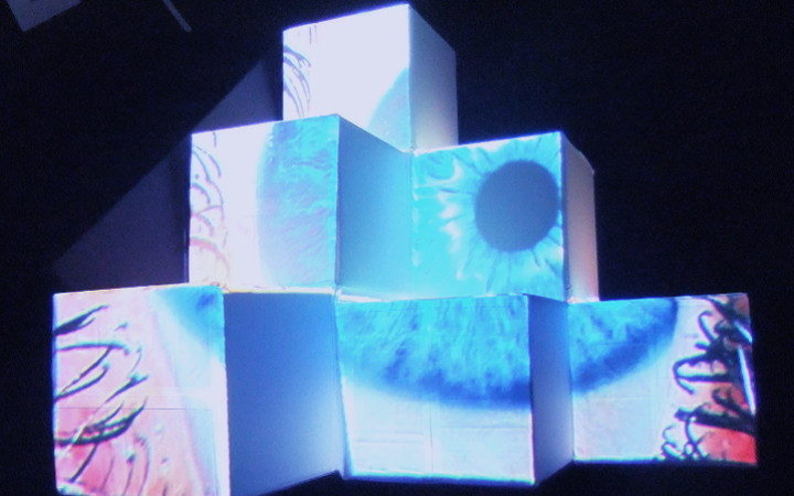
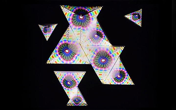
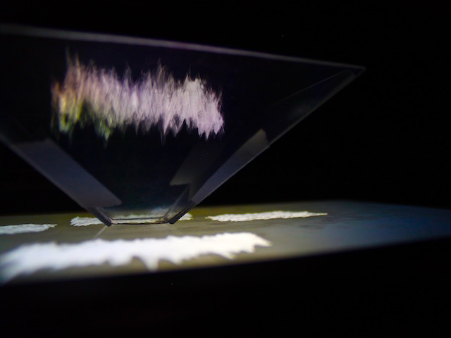
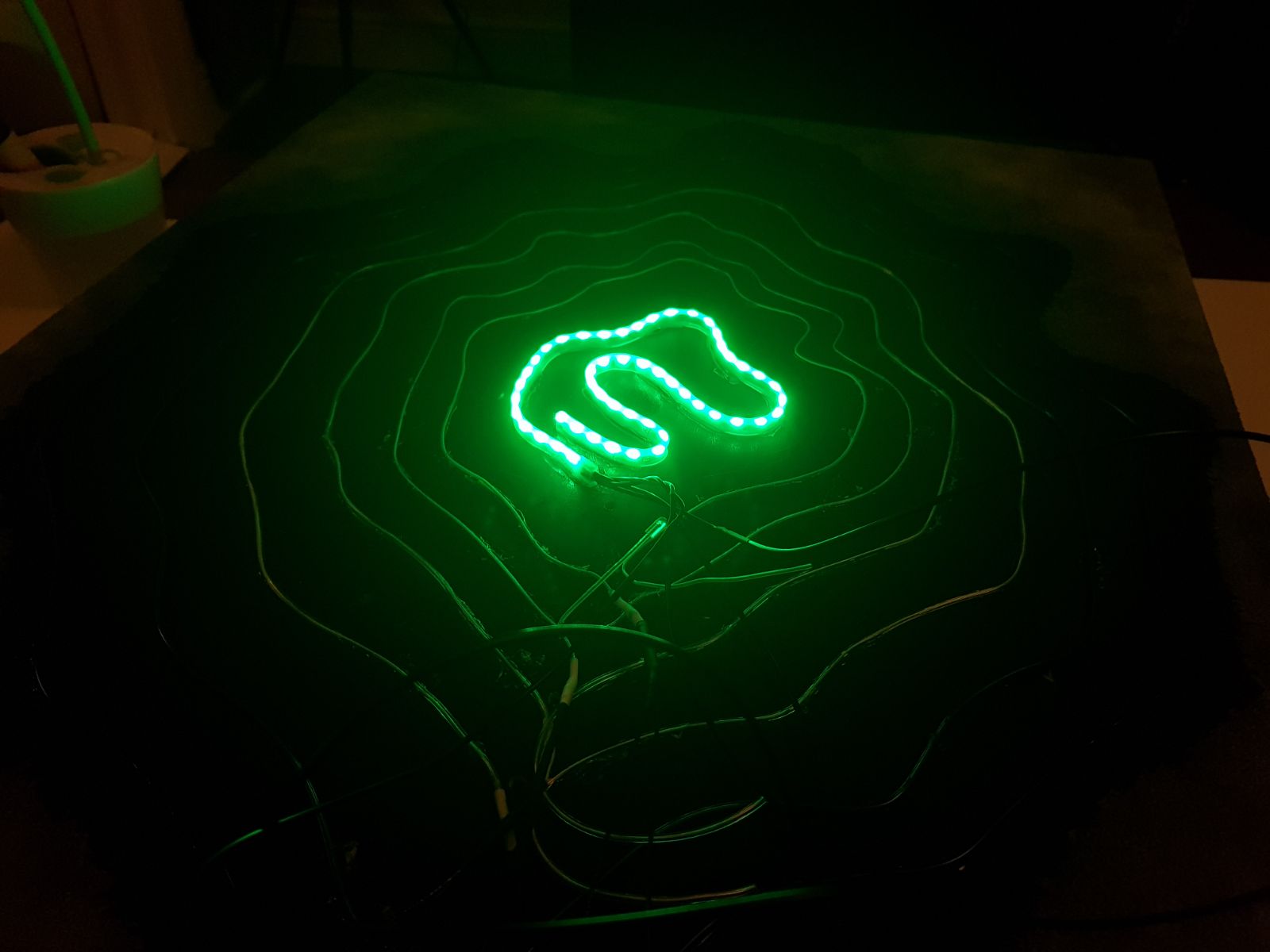
This painting aims to offer a contemporary interpretation of the shadows in the cave by substituting them with digital light, a physical paradox but perhaps the best conceptual equivalent; it aims to create an illusory space which, coincidental with the situation of the prisoners, presents the audience with fleeting images of an alternate space - what they choose to believe or what they interpret the image as is up to them. This idea of simulation, of playing with perception and depth, aims to turn the age-old Myth of the Cave on its head; by using digital, computationally-controlled light as a symbolic manifestation of the virtual, alongside traditional painting techniques, it aims to offer a dynamic visual representation of how the ‘virtual’ and the ‘real’ overlap today, whilst at the same time playing with spatial configuration and perception.
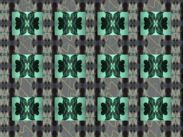
DESIGN
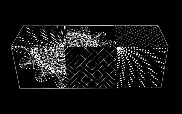
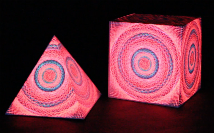
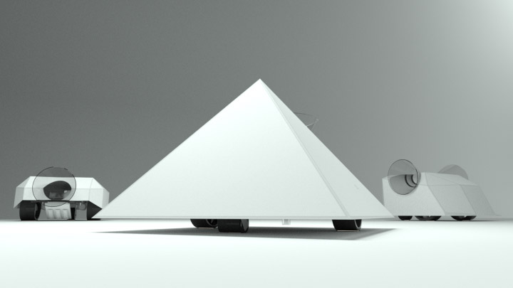
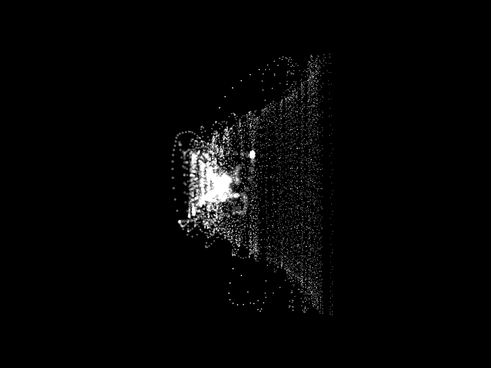
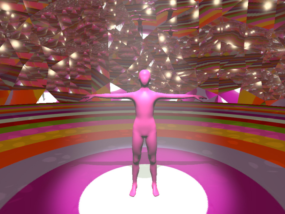
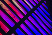
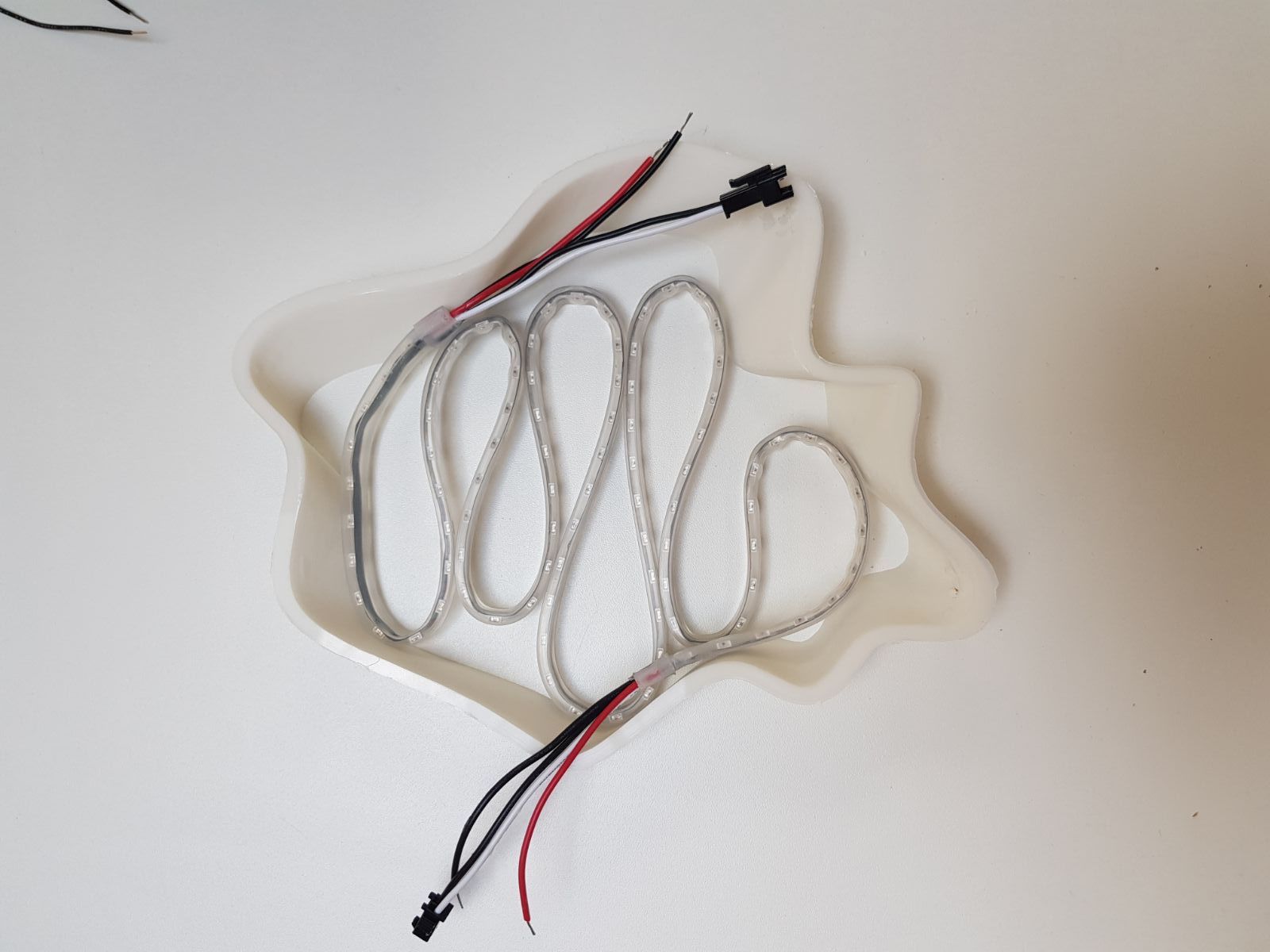
In terms of design, the visual parameters of this piece emerge from my experimentation with creating 3D models that reference fluid, organic shapes. The design concept thus bases itself around this abstract shape, which was then expanded to encompass the majority of the canvas; the electroluminescent wires were bent to fit this idea in order to create a tunnel-like shape that can appear to both go inwards and outwards. The 3D model became a sort of “housing” for the LED strip, in order to create a smaller, brightly lit, version of the shape which contrasts with the dark, static, painted one.
Final design page:
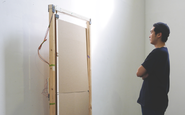
FABRICATION
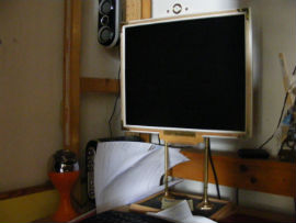
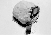
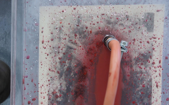
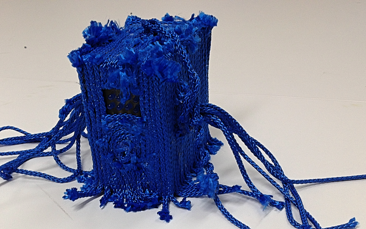
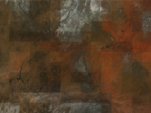
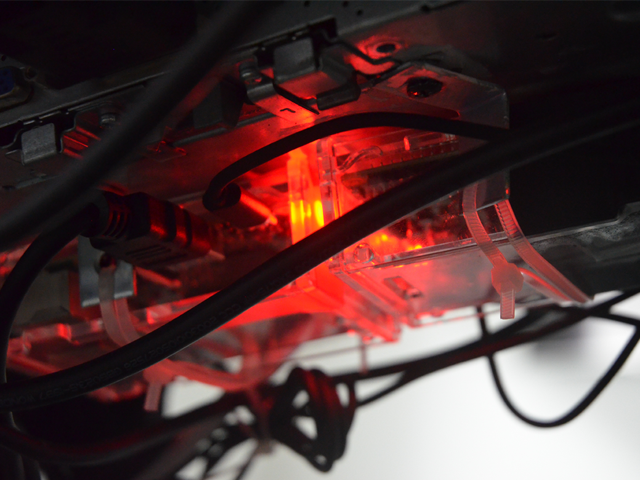
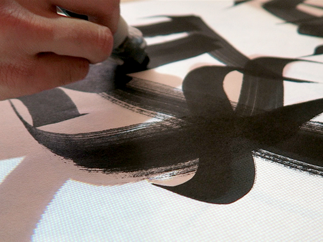
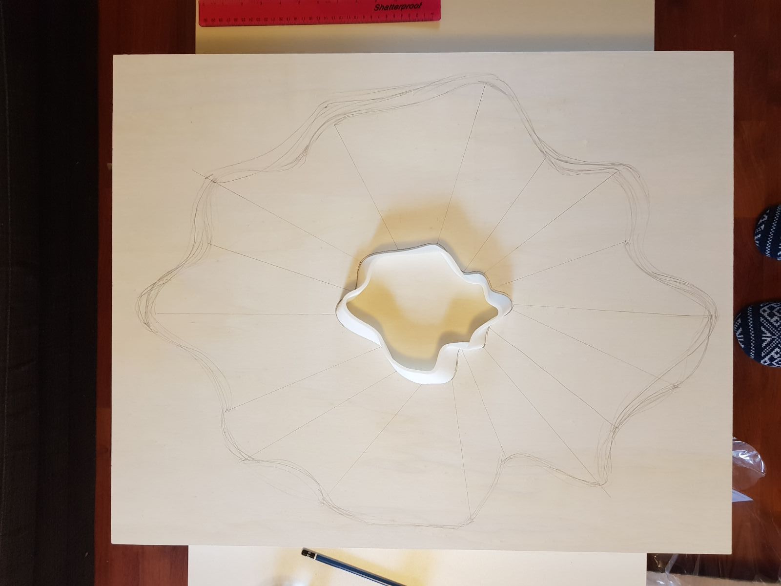
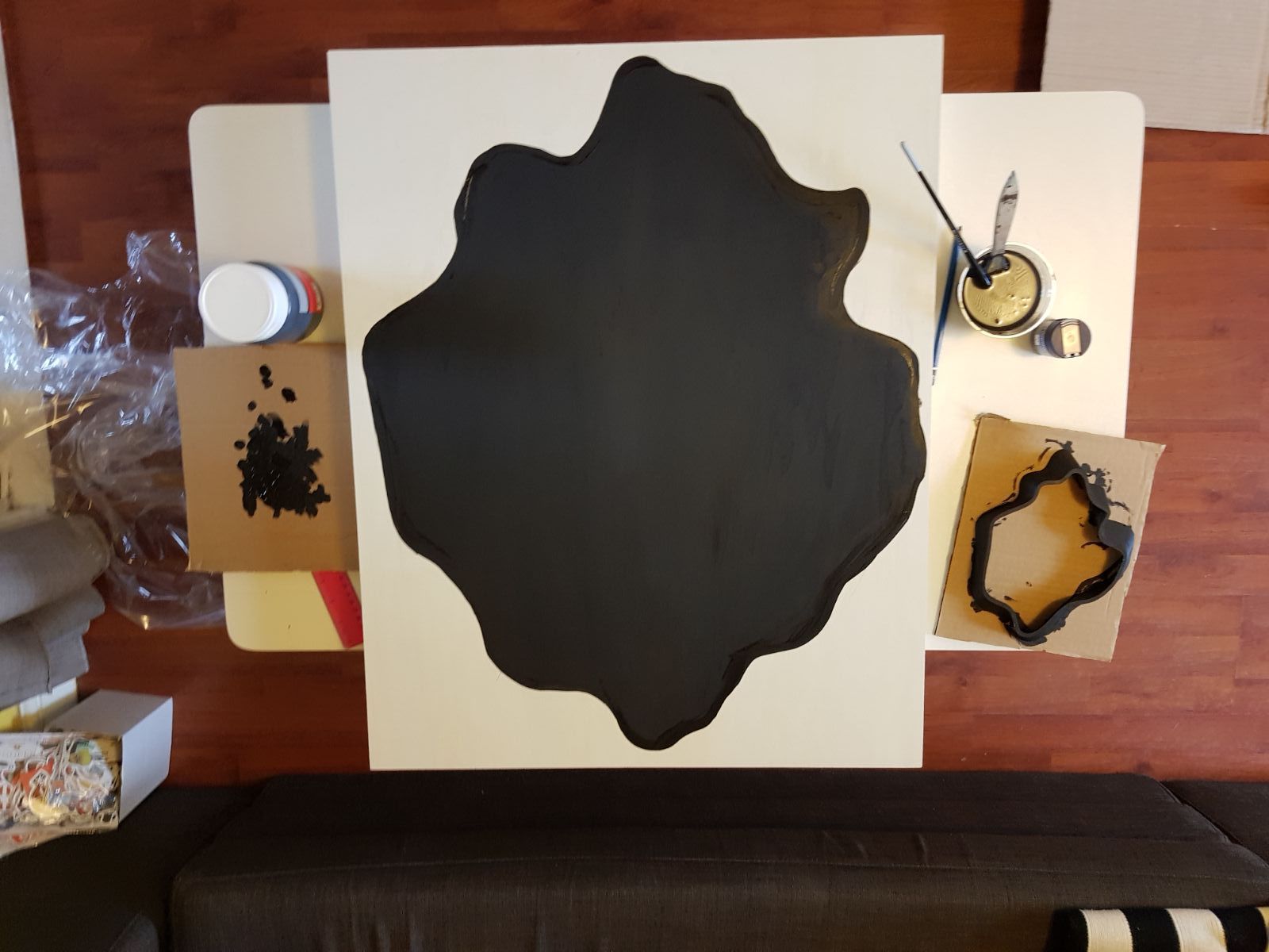
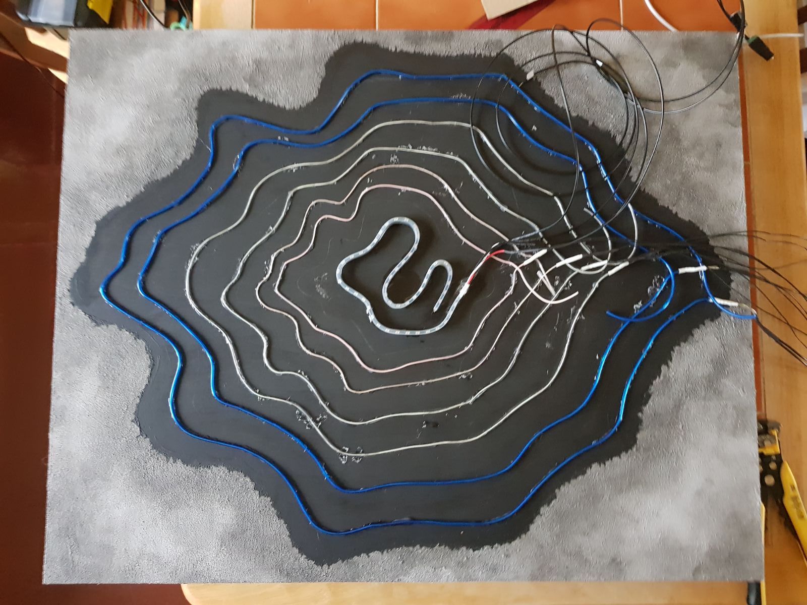
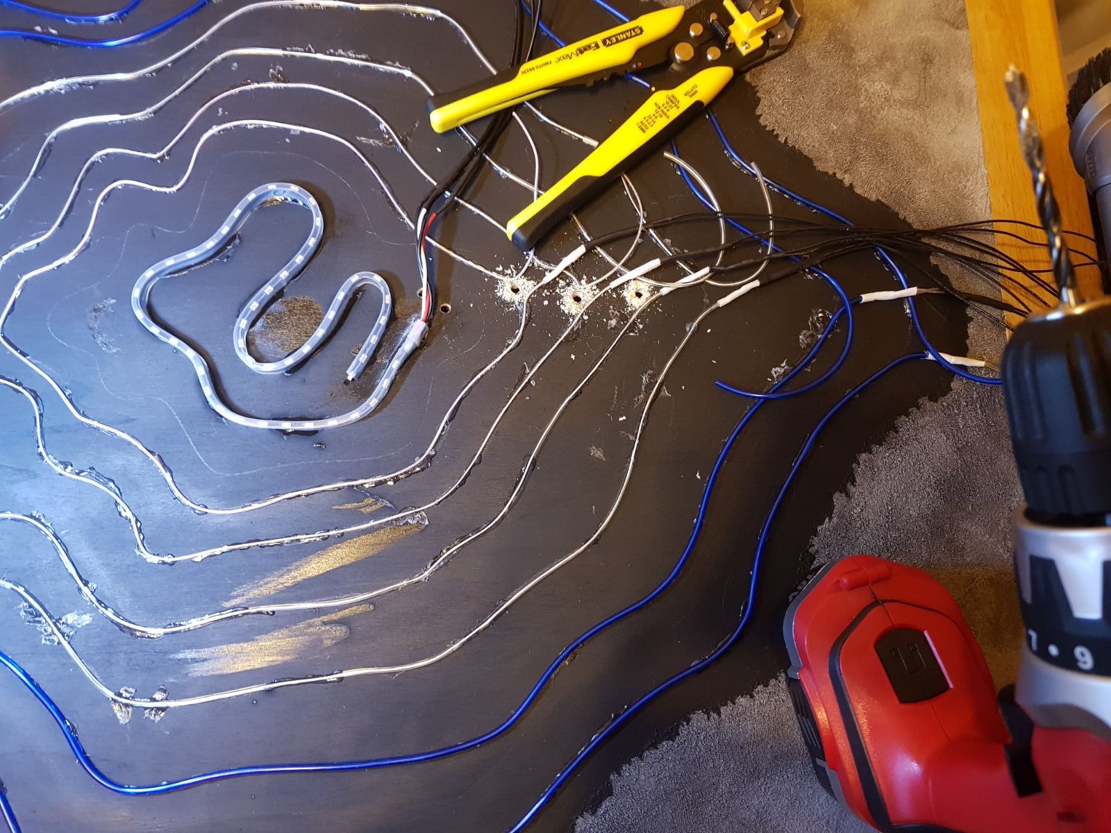
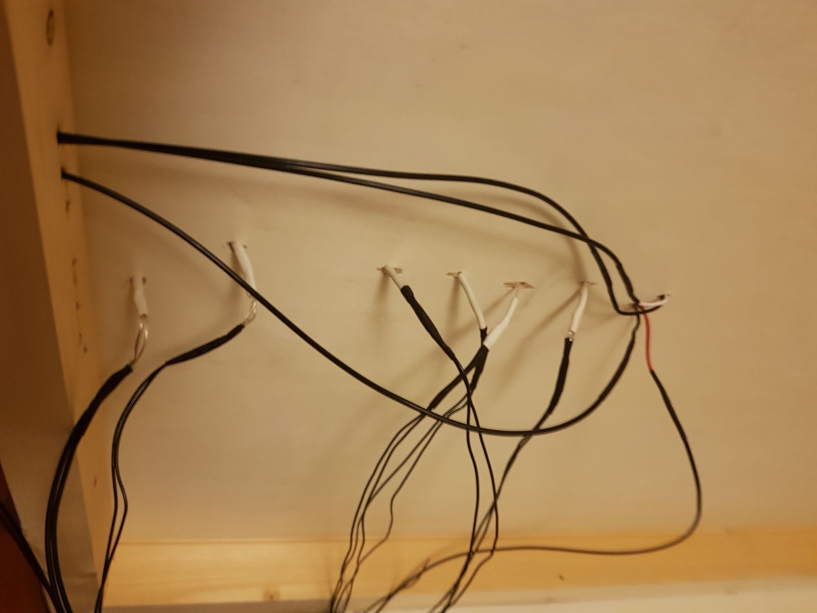
I started out by creating a sort-of fluid, organic-like shape that would fit with my sketches and design page. From there onwards, I proceeded to print out the shape for the centrepiece and use it as a guideline for attaching the neon wires and creating the the main background shape, which was then painted in a uniform matt black colour, whilst a concrete-like texture effect was added to the outside of it, using acrylic paste and different substances to thicken the paint, such as marble dust. Once the support was finalised, I traced where the outline of the shape would fall once again and marked a path for each el wire strand. I then proceeded to glue the wires to the painting using a glue gun - this was a step that posed many unexpected problems, as the nozzle of the glue gun was much wider than the wire itself, making the glueing process very difficult and messy. After each strand of wire was glued to the surface of the painting, I drilled holes into the surface of the panel in order to hide the cables behind the painting. Holes were also drilled in the bottom beam of the panel frame to ease making the connection and avoid pressure on the wires by having the weight of the painting on them when pulled out from underneath. In between the glueing, drilling and cable routing the lights were constantly tested. Despite the connections I soldered being protected with heat shrink tubing, some of them still got damaged in the process and needed repair, and a few wires had frayed and nearly broke and required soldering. I found it was best to keep testing after each new action that altered the electrical elements.
Here are some process photos:
TECHNICAL
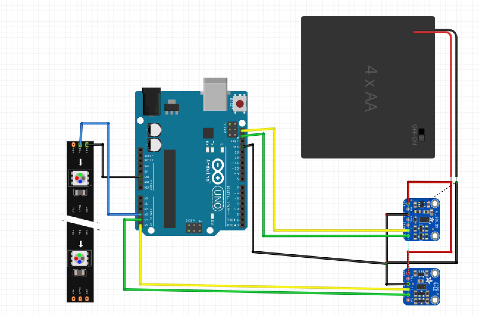
Circuit overview:
The gesture and distance sensors are connected to the Arduino via SCL and SDA; this was an ideal setup as the El Escudo shield needs to make use of all the digital pins on the Arduino. They are externally powered with 5V via a 4xAA battery pack. The Neopixel strip is driven from pin A3 and connected to an external 5V supply. The shield itself drives 6 strands of El Wire and makes use of a 12V inverter
PARTS: 6 x El Wire strands, 12V inverter, El Escudo Dos Shield, Side Light Neopixel Strip, DC Power Supply, Screw Terminal to DC adapter, 1000uF Capacitor, 470ohm resistor, Adafruit VL53L0X time of flight distance sensor, Adafruit APDS9960 gesture, proximity and RGB sensor, 12V power supply.
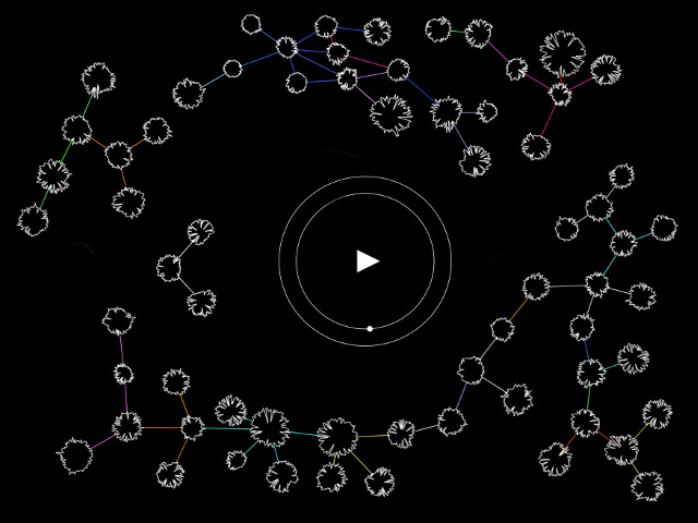
Code overview:
The code makes use of switch cases - each case is a different animation effect or a different level of how lit the painting might be (dependent on the sensor, the values either trigger the painting to gradually light up or trigger more complex, dynamic visuals). The values received by the distance sensor make the wire strands light up one by one according to how close the distance recorded is to it through the use of if statements. The code also links the animation sequences to the gesture values recorded by the gesture sensor (up, down , left and right each trigger their own light effect).
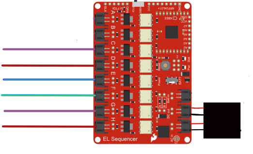
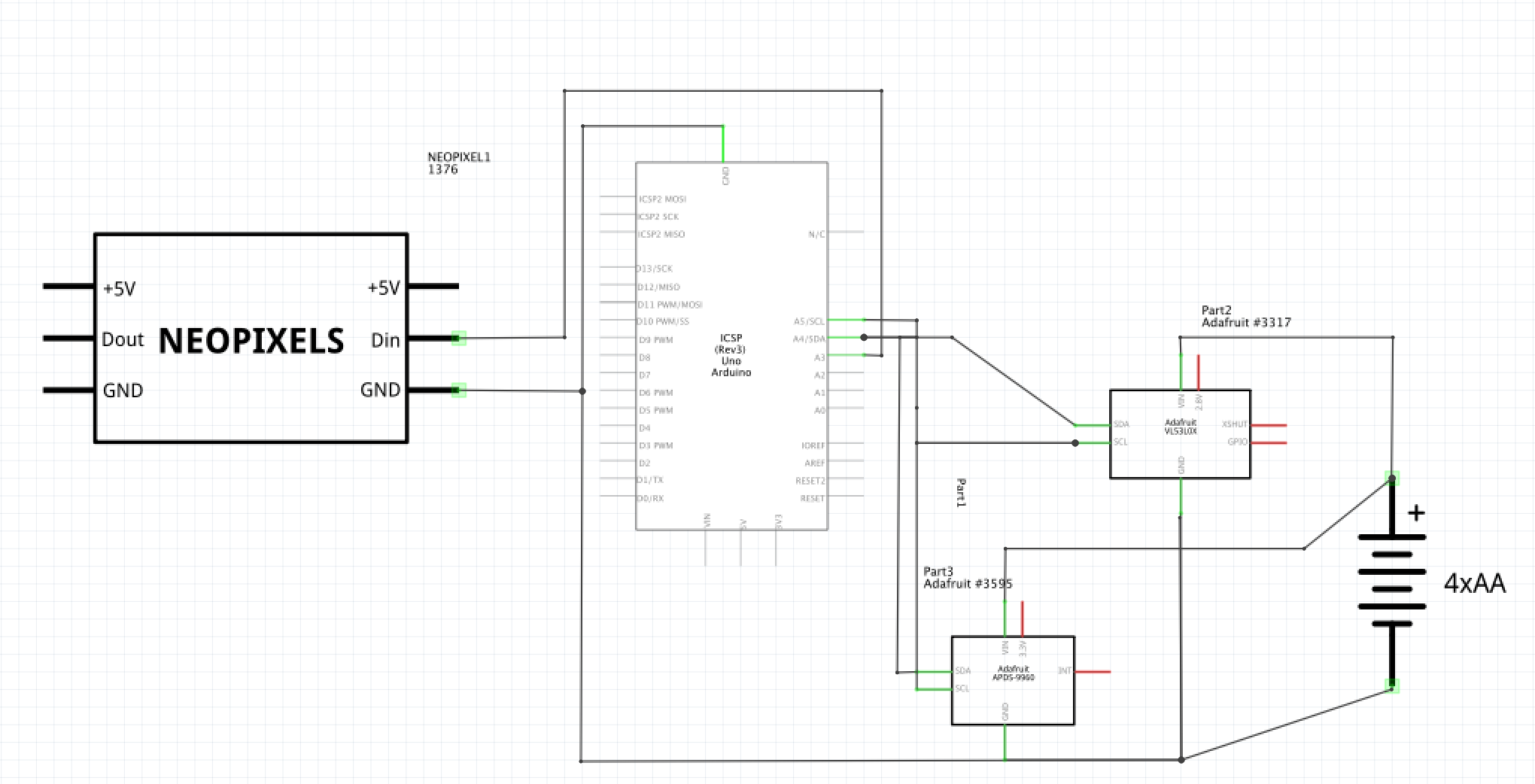
Schematic:
This is sort of a two-part schematic; the first image indicates the connections made to the Arduino itself, outside of the pins used by the shield. The second schematic shows the shield and the respective parts being driven by it. This is due to the nearly non-existent documentation for the Escudo in terms of parts file that could be added to Fritzing. The official schematic offered by Sparkfun seems to detail the individual parts of the board rather than the shield itself as a standalone object (it can be accessed via the link here: https://cdn.sparkfun.com/datasheets/Components/EL/EL_Escudo_Dos/EL%20Escudo%20Dos%20v21.pdf). In light of not being able to implement the actual part, I edited the one photo they offer as guidance for hooking up the shield to fit my own circuit.
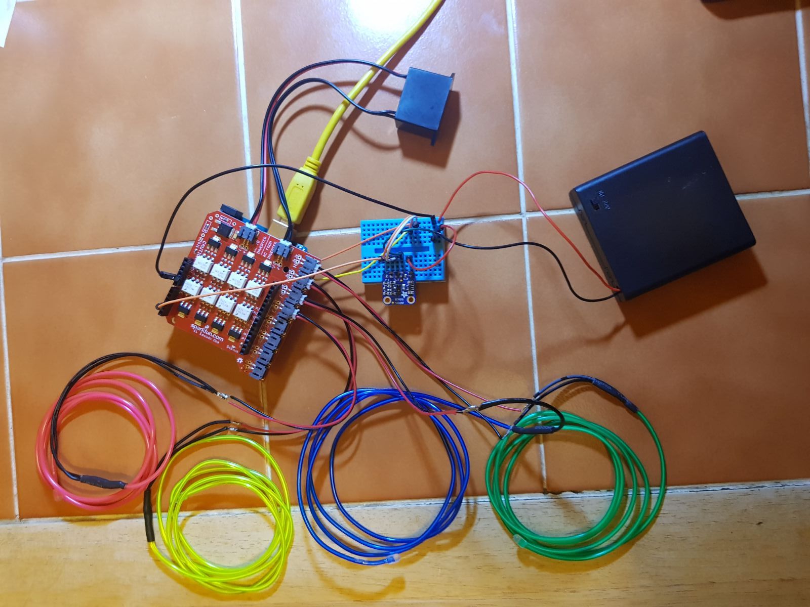
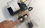
Here are the schematics, plus a photo of the dummy circuit used for testing and fine-tuning before porting the circuit to the actual painting: