


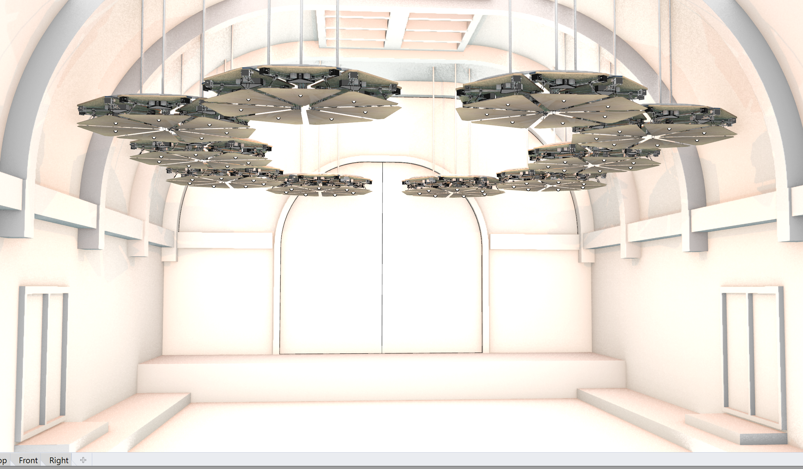
Sound Mirror
Sound Mirror is a proof of concept for a kinetic instialtion to alter the acoustic reverberation of the space that it is within. The object is designed to be responive to a number of potential sensor inputs, or a pre defined set of patterns to affect the reverb acording to preference.
produced by: Edward Ward
The Design
The projct took on many facets before concluding on the idea for Sound Mirror. My iniital sources of inspiration were from of the kinetic walls that have been popular online for some time now. Not content with simply making one for the sakes of making one - I spent some time to create a story / develop the concept behind the work - as I feel this is something that can carry the project, and my motivation for it to be completed! So with keeping the kinetic wall, I deceided that it would be responcive to a user in a space - that it could either follow a person around so that sound can be focused onto them - or - reflect the sound in a room to a users specification.
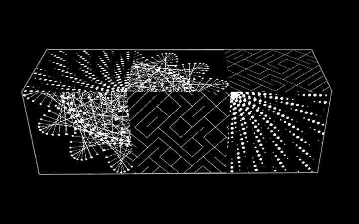
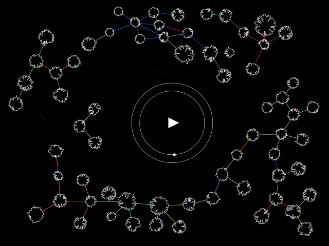
I made a visual for how I envisiage the objects to react to a user in the space. the pointis controled by the sliders, and the point then updates the normals of the surfaces. the surfaces follow the point around the space.
I thikn the latter has more useability / scope as a real thing, as acoustic solutions are always pretty standard and basic. This would allow for the refelection of sound - to move teh echo around. An Ida I had would be to have the center of the shape to be able to rotate, to reveal a softer textile / foam that could absorb sound opposed to reflect it.
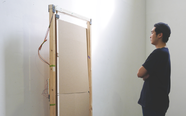
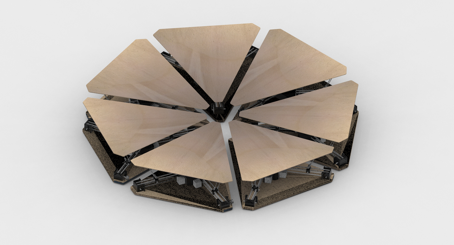
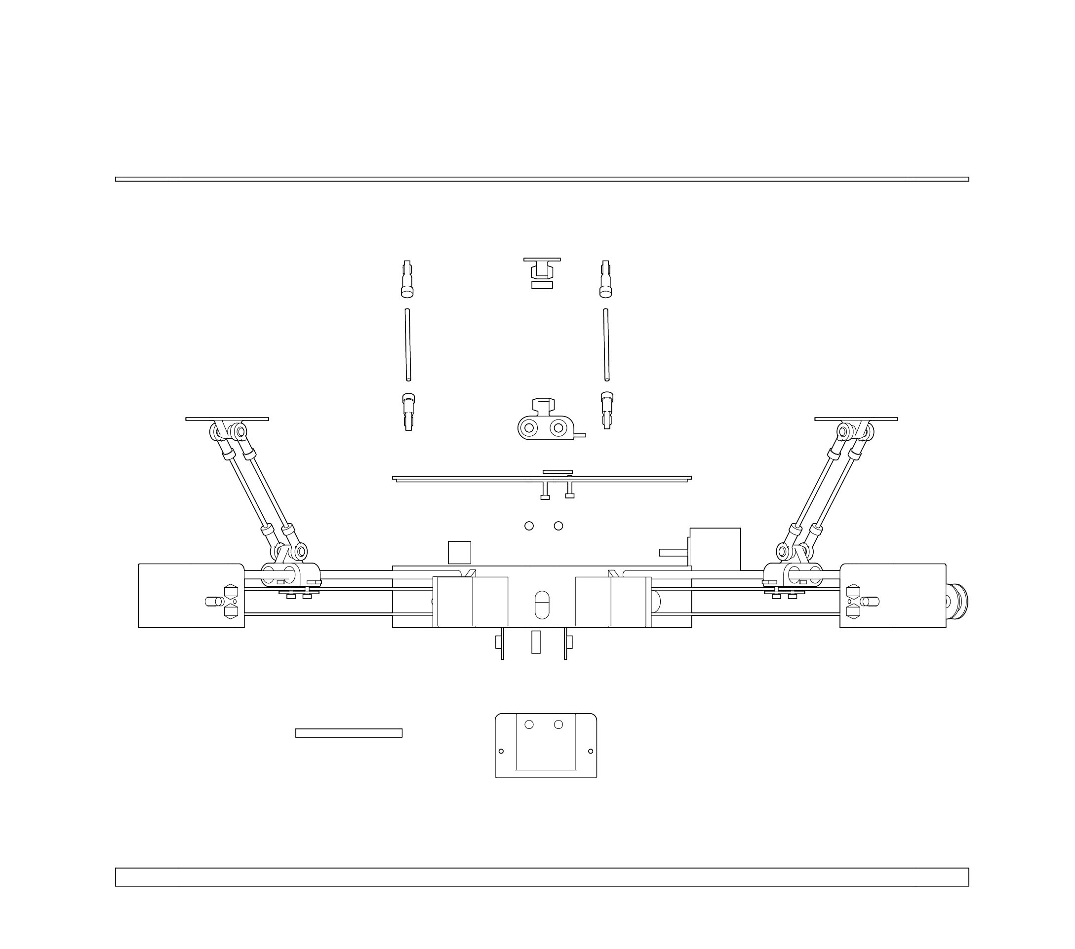
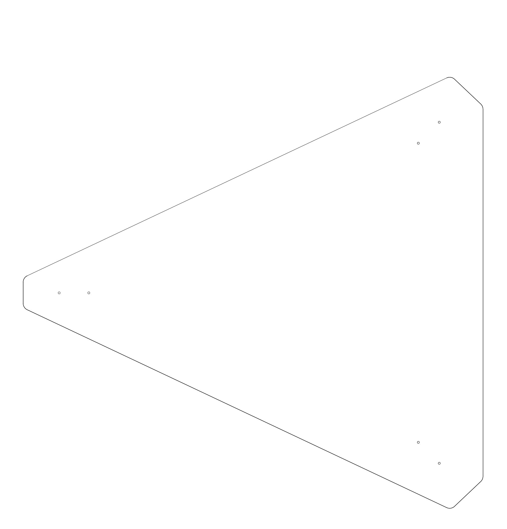
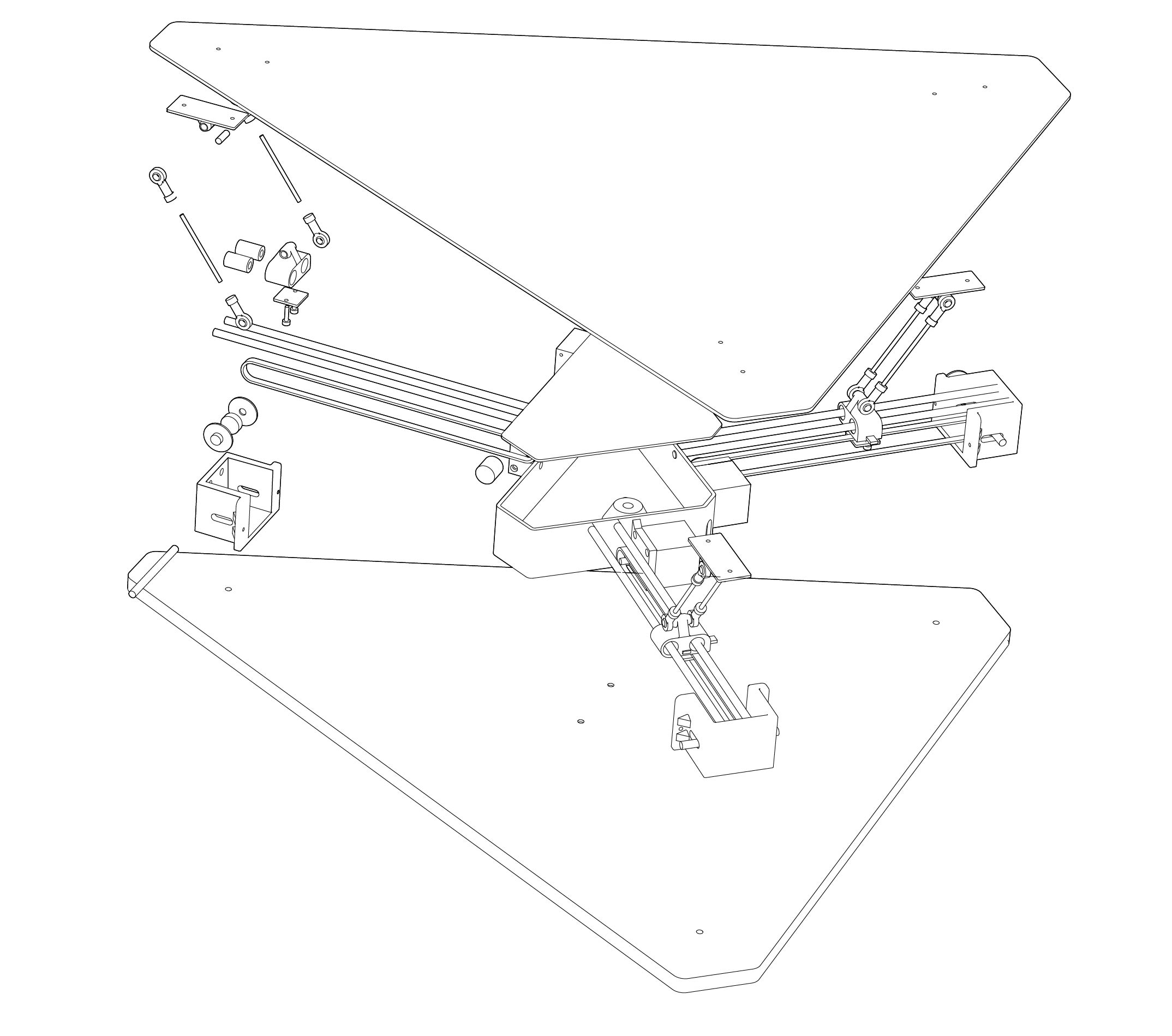
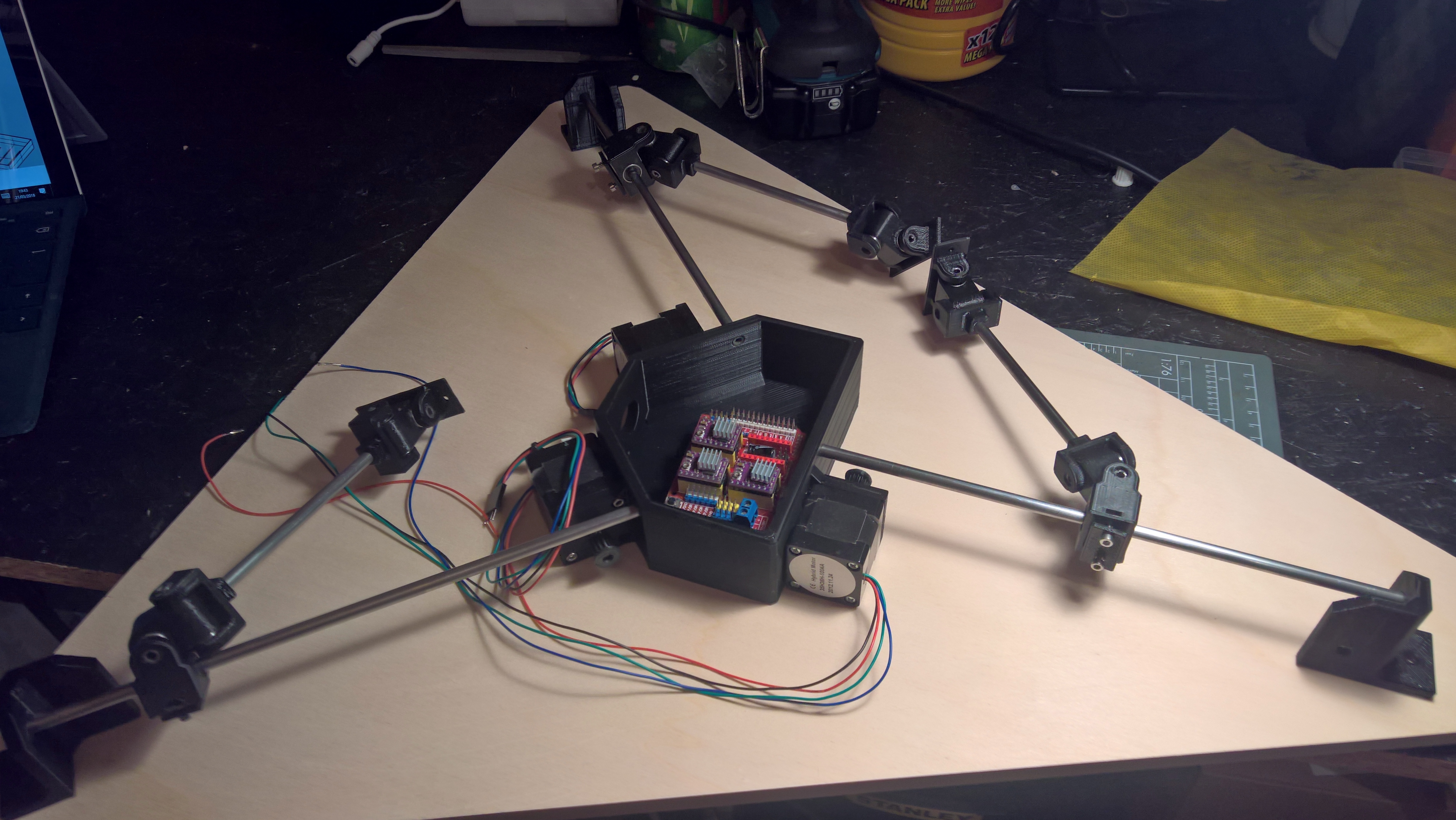
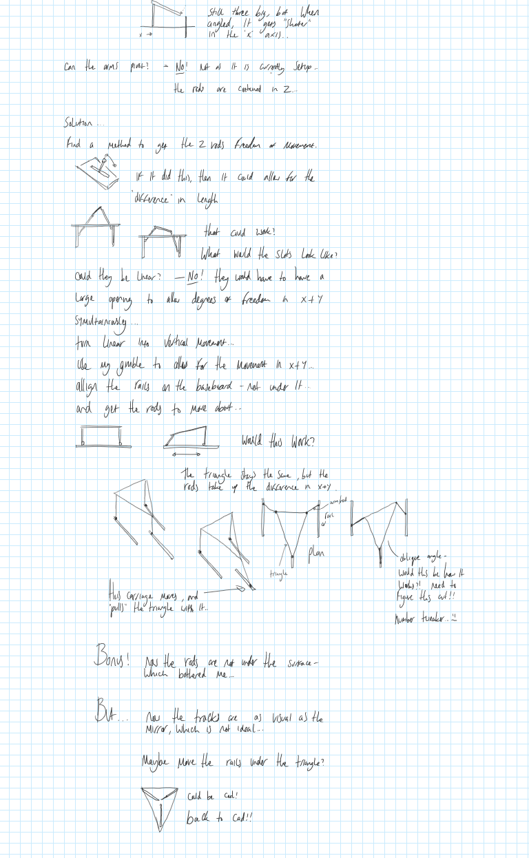
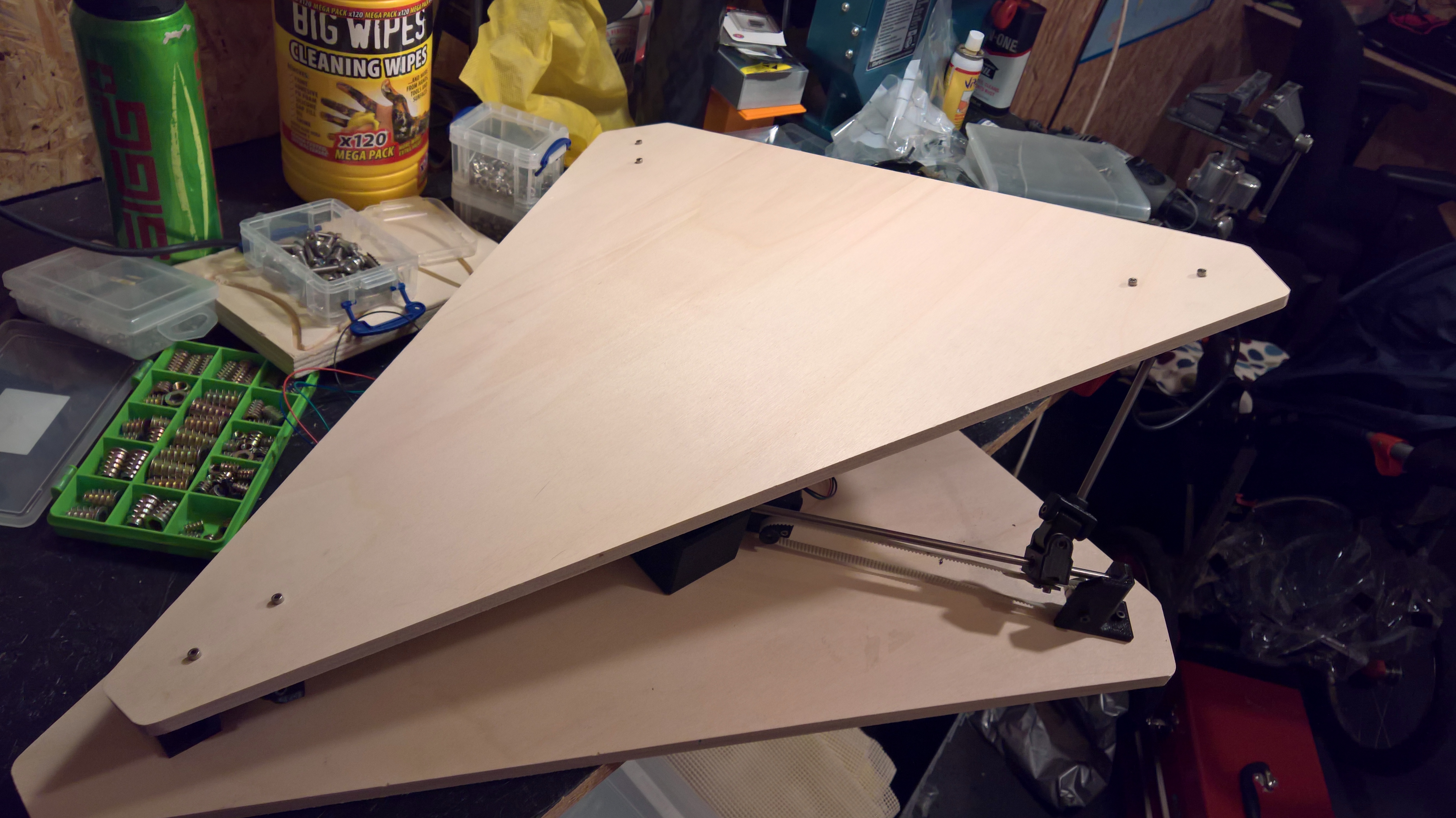
The below image gallery is of v1, where it sort of worked but didnt really. I found out early on in the projct that the angle of the triangle would affect the relative lengths to its connector on the z axis. This is a problem as it would allow for the dynamic movement ineeded. One way around this was to move the linear rails from the z axis and put them on the ground plane / x, y axis. this way the movememnt could be compensated for by moving the rails together (this was al assumpton untill i built it!) It also had the benifit of not requiring the extra depth between it and the proposed ceiling.
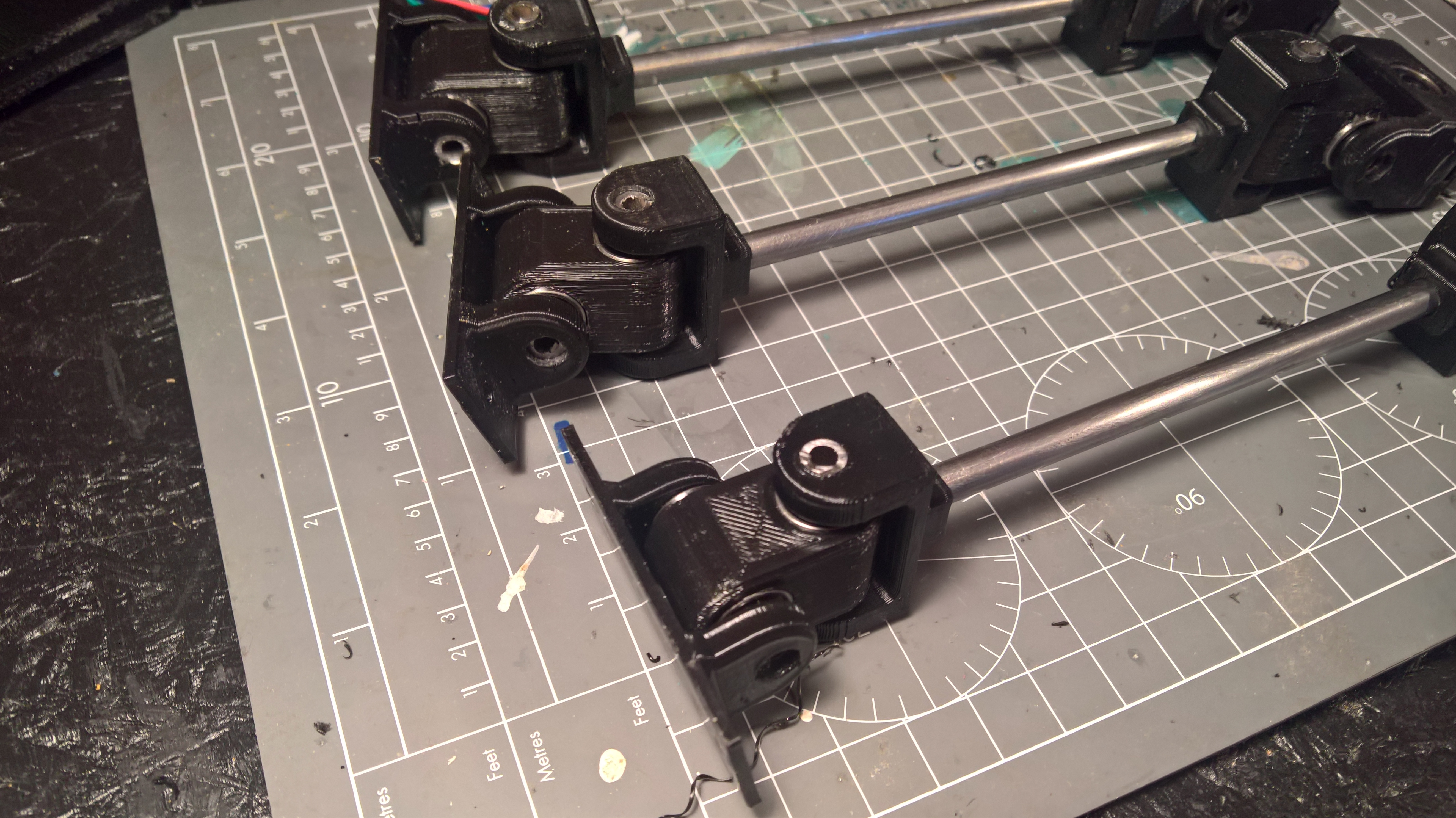
I built v1.0 and it sort of worked - the problem with the gimble shapes that I made was that it were all wobbely (as per the design) - but this had a terrible consiquesnce - it wouldnt suport its own weight and the thing just slumped and wouldnt do what i wanted it todo.
incase the below embeded video doesnt work:
Great sound quality :s
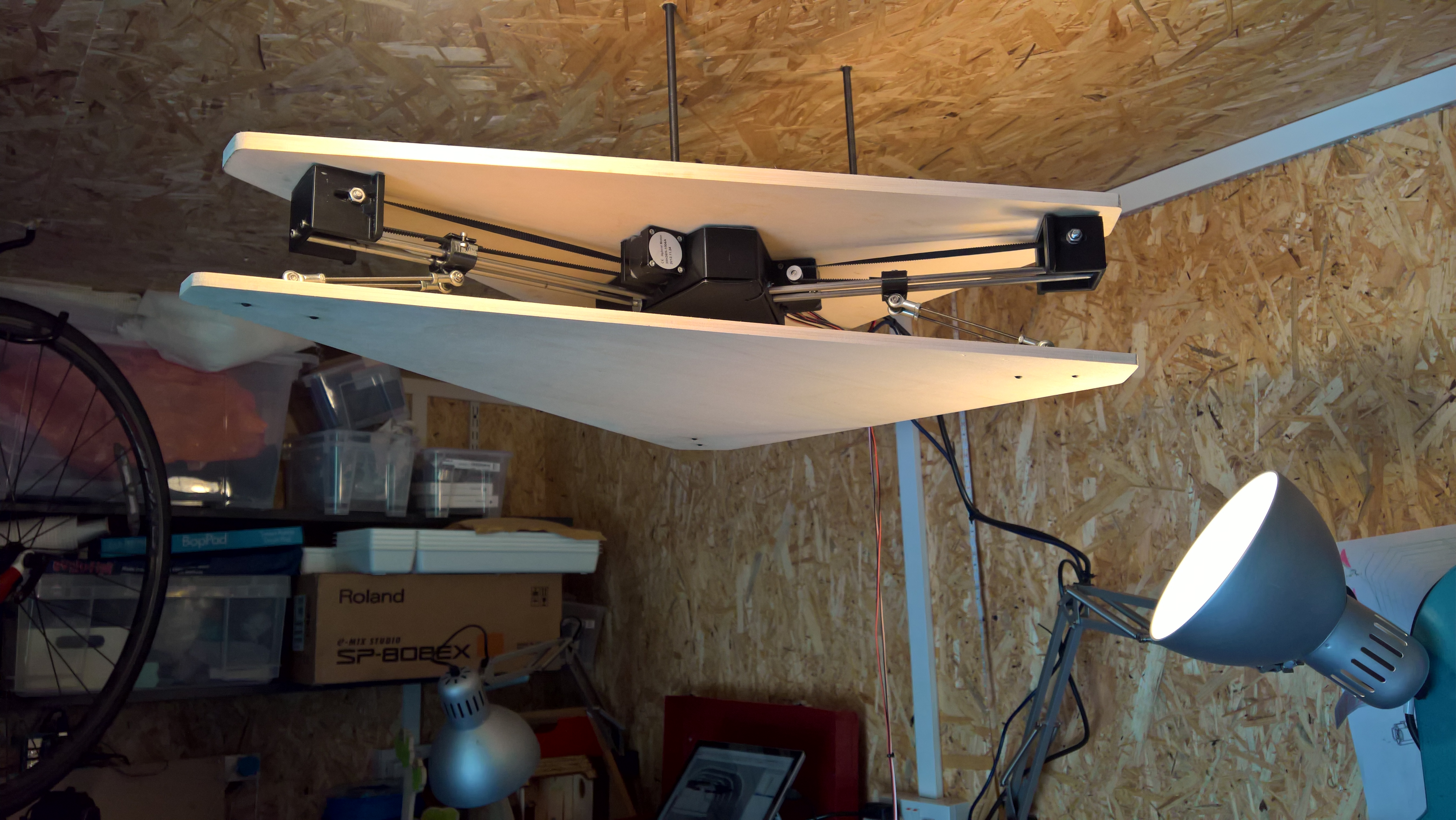
after a nights panic, i had a brain wave and decided to mount the work upside down - and let gravity do the work for me! it is after all designed to be suspended upside down! 😉
It sorf of worked upside down, but then I had errors with the motors moving and the libraries used. After all, the demos on youtube we easy yet I was having a bit of a nightmare!
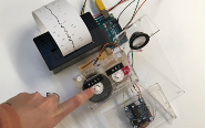
Stepper test working with sliders woo! Code at bottom of page
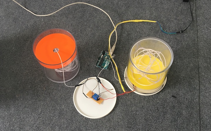
The motors and stuff
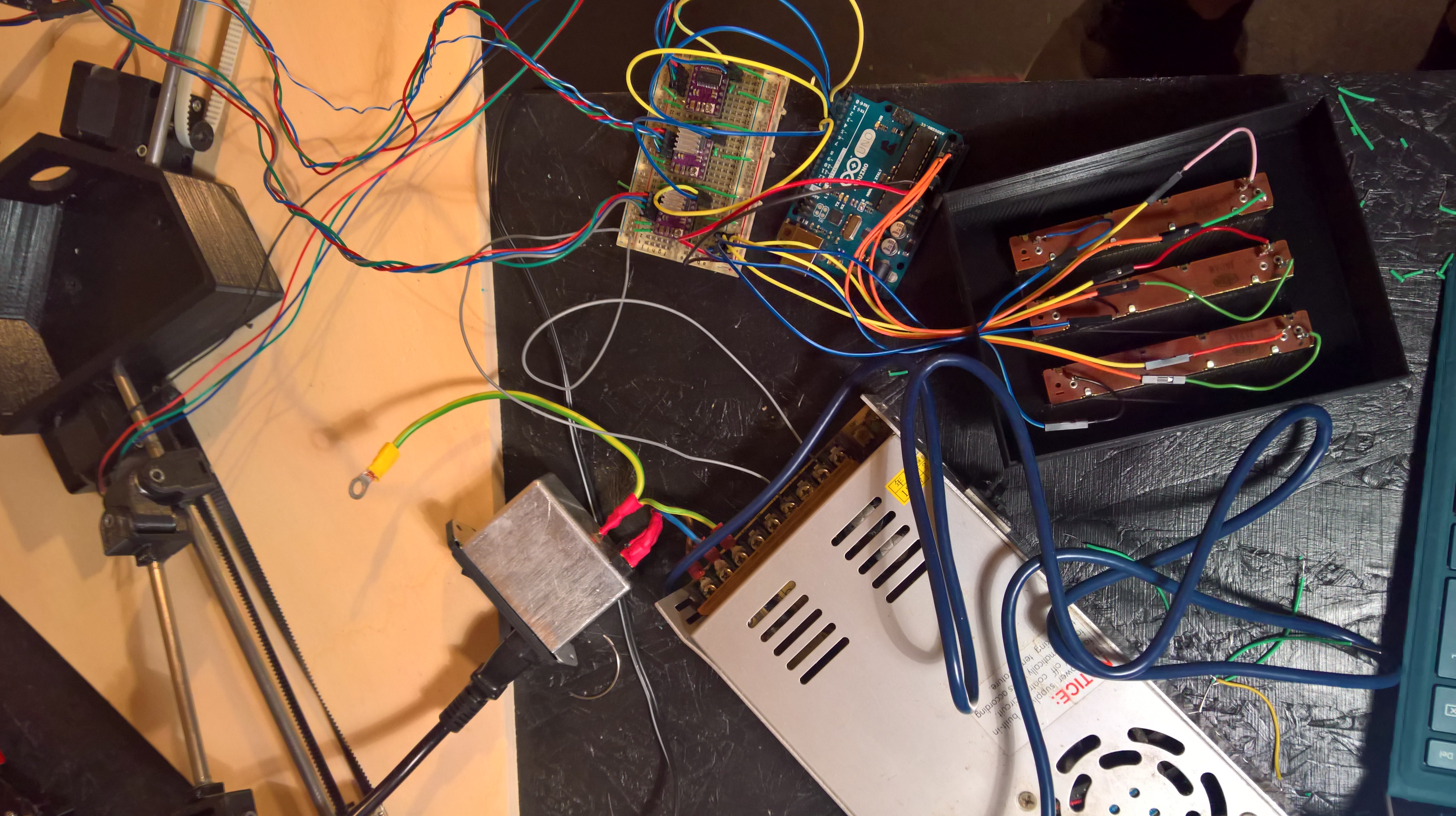
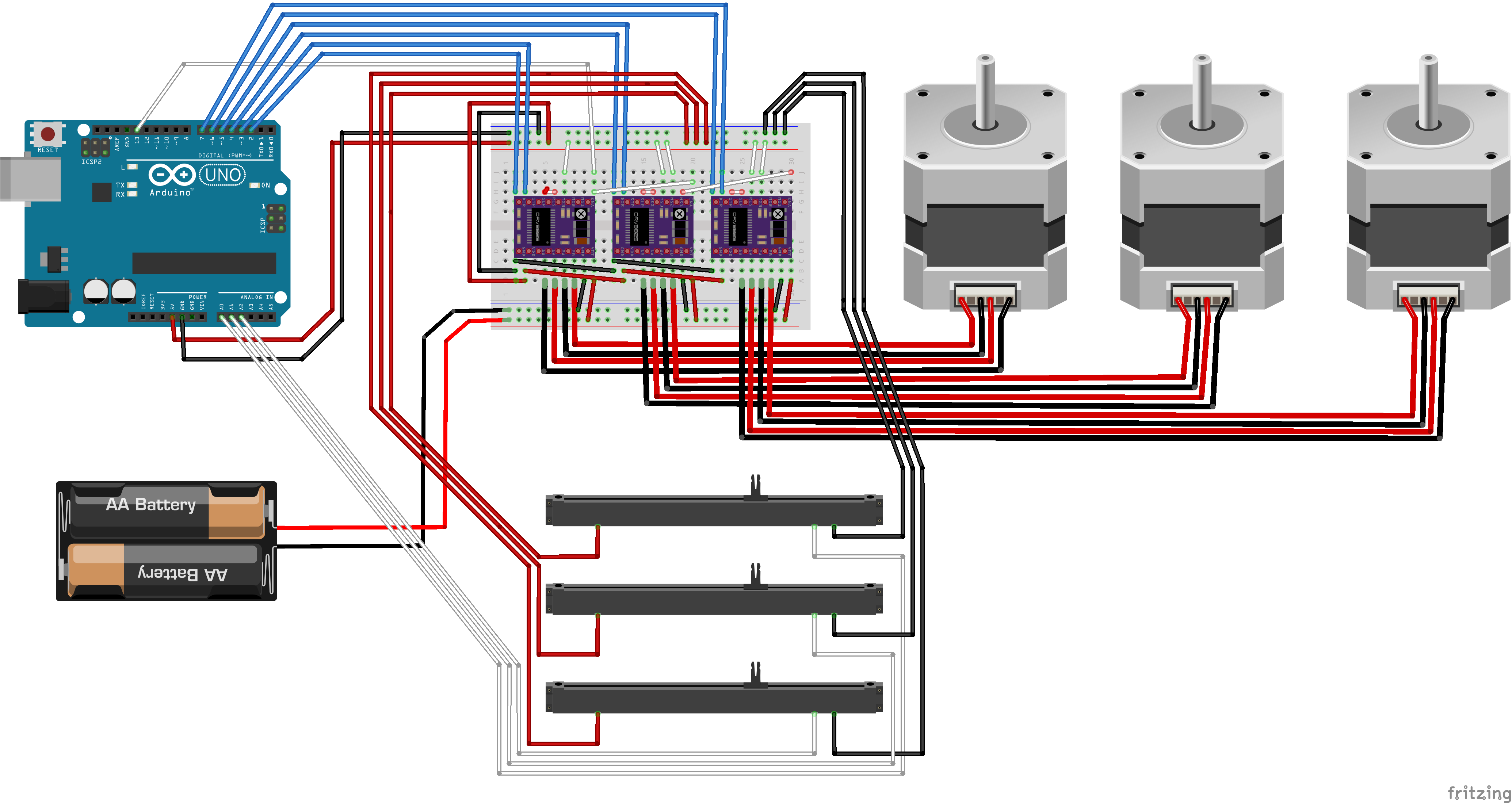
Yes so the motors were / are a pain. I wanted to use the CNC sheild but that wasnt moving anything. I hav e abunch of stepper drivers in the drawer that I wanted to use. After going througha few libraries I focused on the accelsteppper library - and going through all the exaples from simple moves to control via a pot - I grasped the opperation. I adapted the control via pot to run 3 steppers independently, without having to use if statemetns. I found taht the if statemnts would mean that if x moved to a val, move motor - would stall the drivers and only run one at a time.
With the thing working on the breadboard, I went back and got it to work on the shield. I had a few things to folow to help alog the way but generally trying everthing 100 times, it worked on the 101st and by that point i wasnt realy sure what the steps I took were the ones that made it work... :s
V2
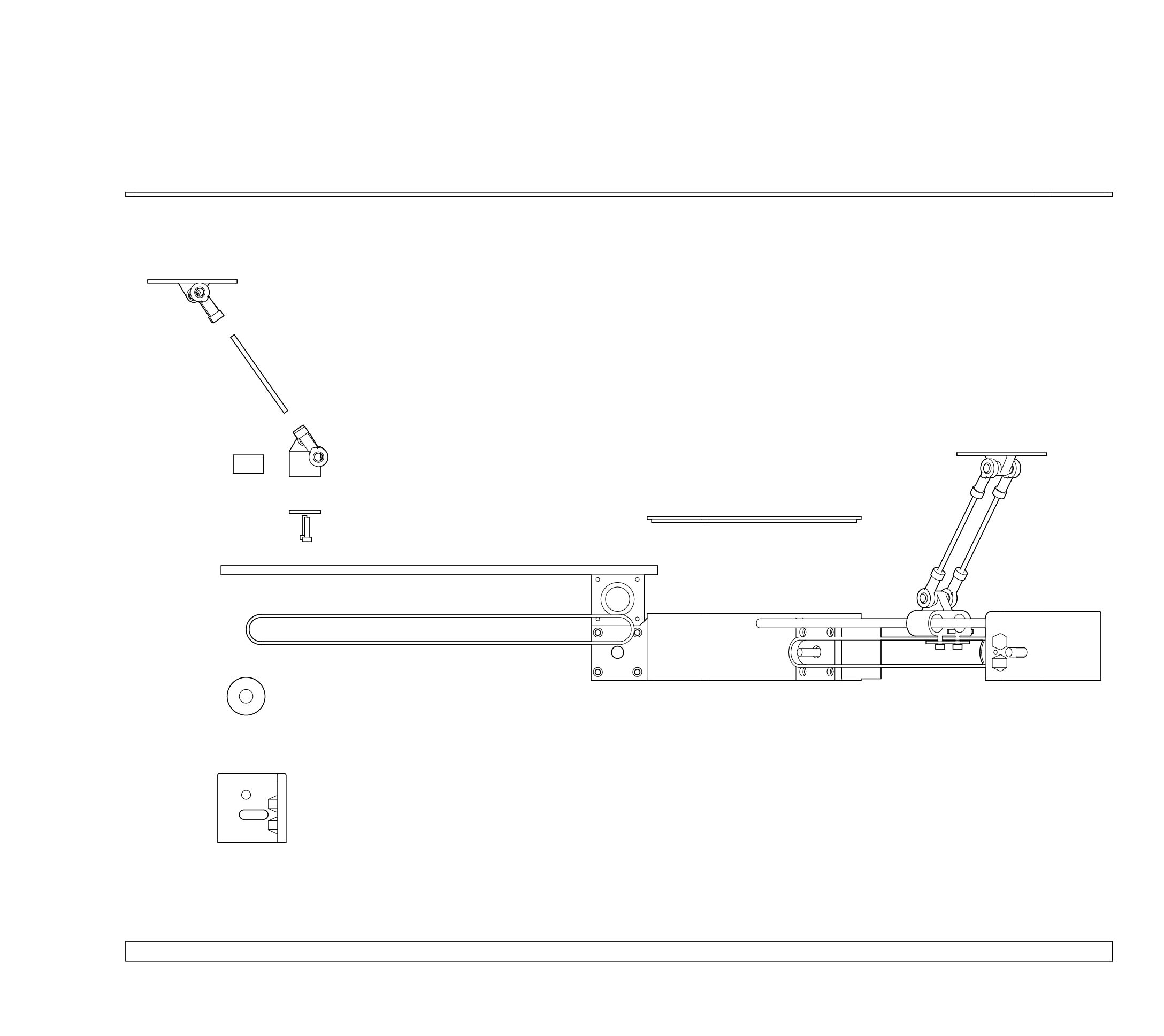
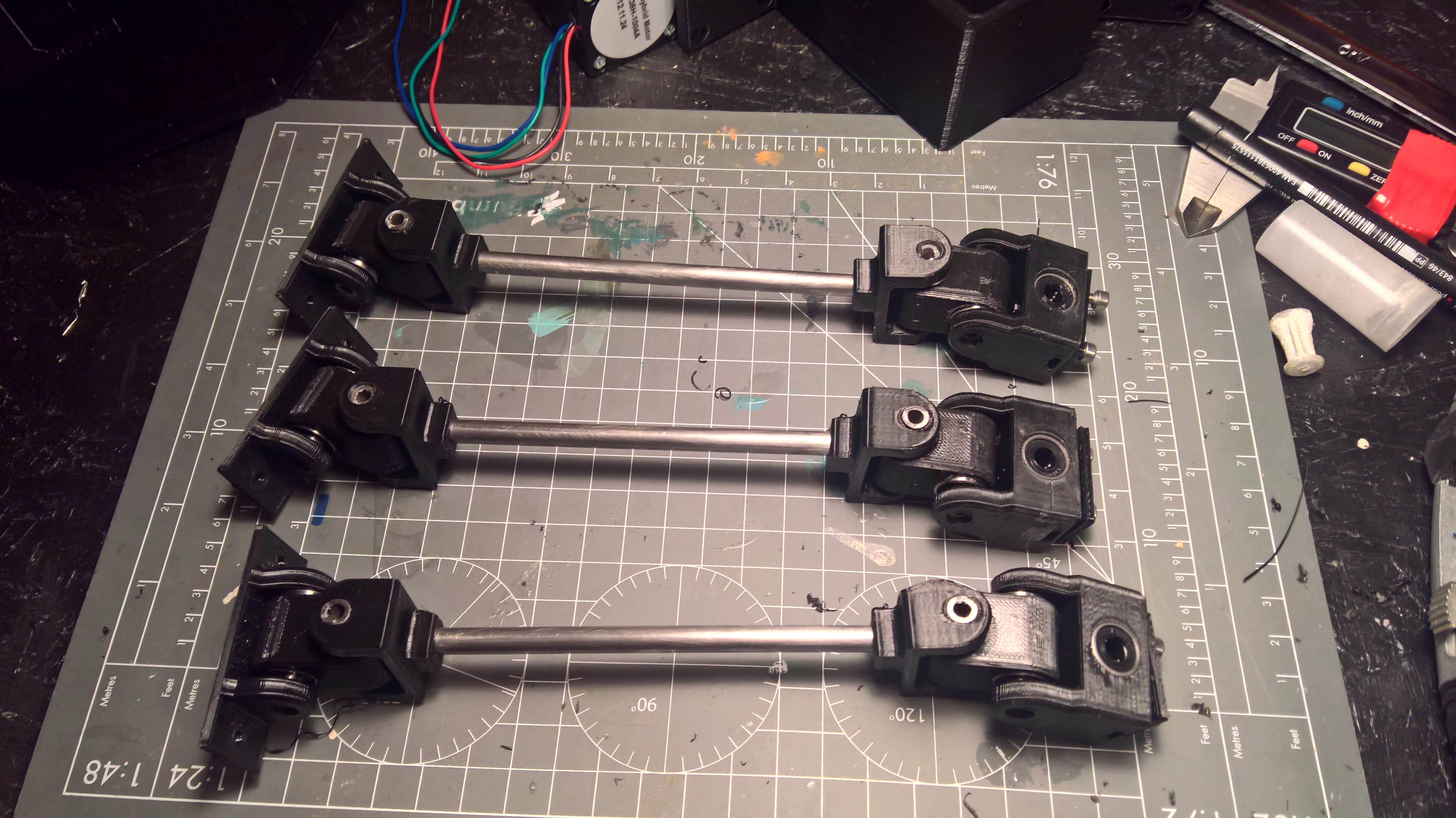
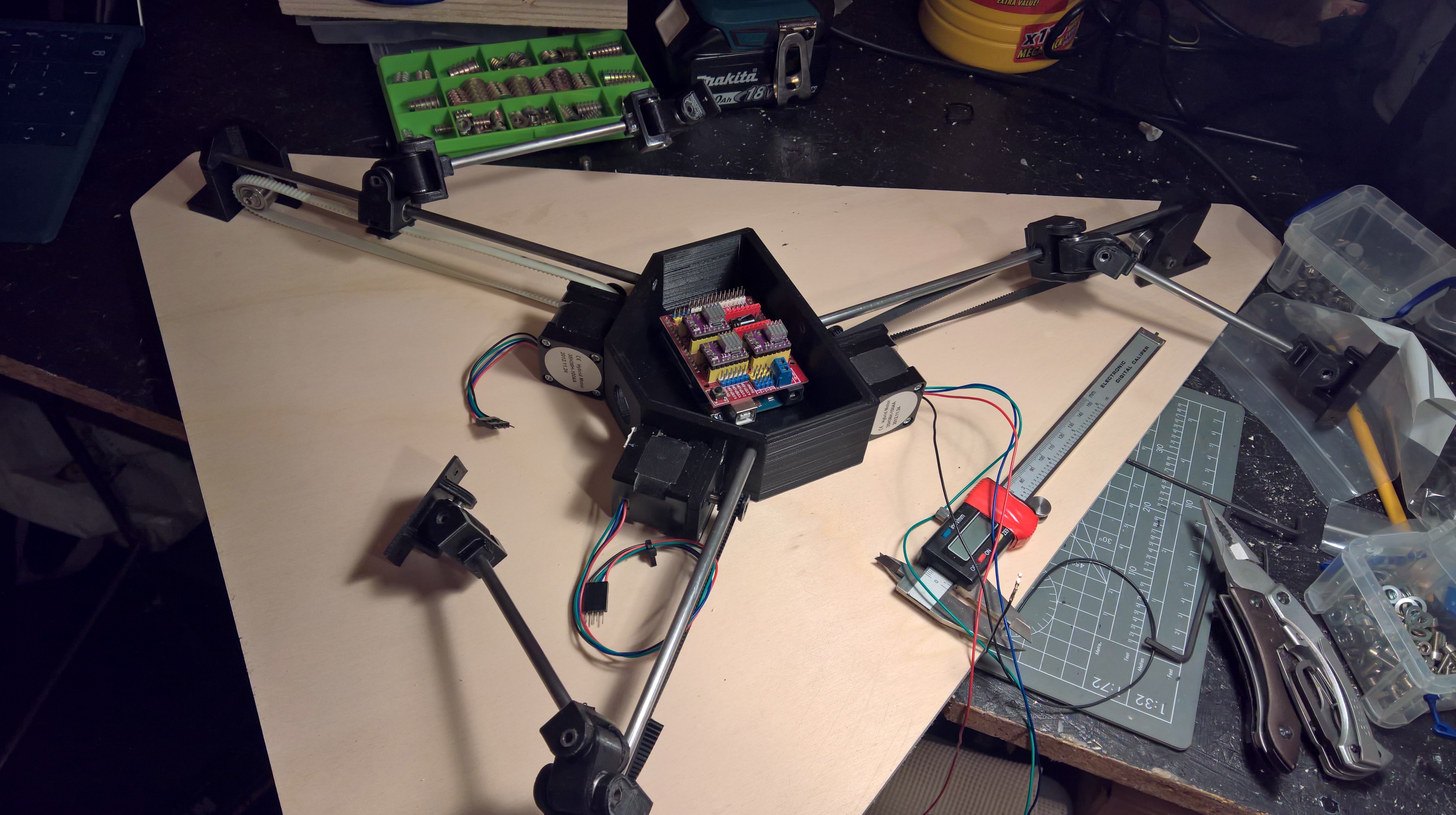
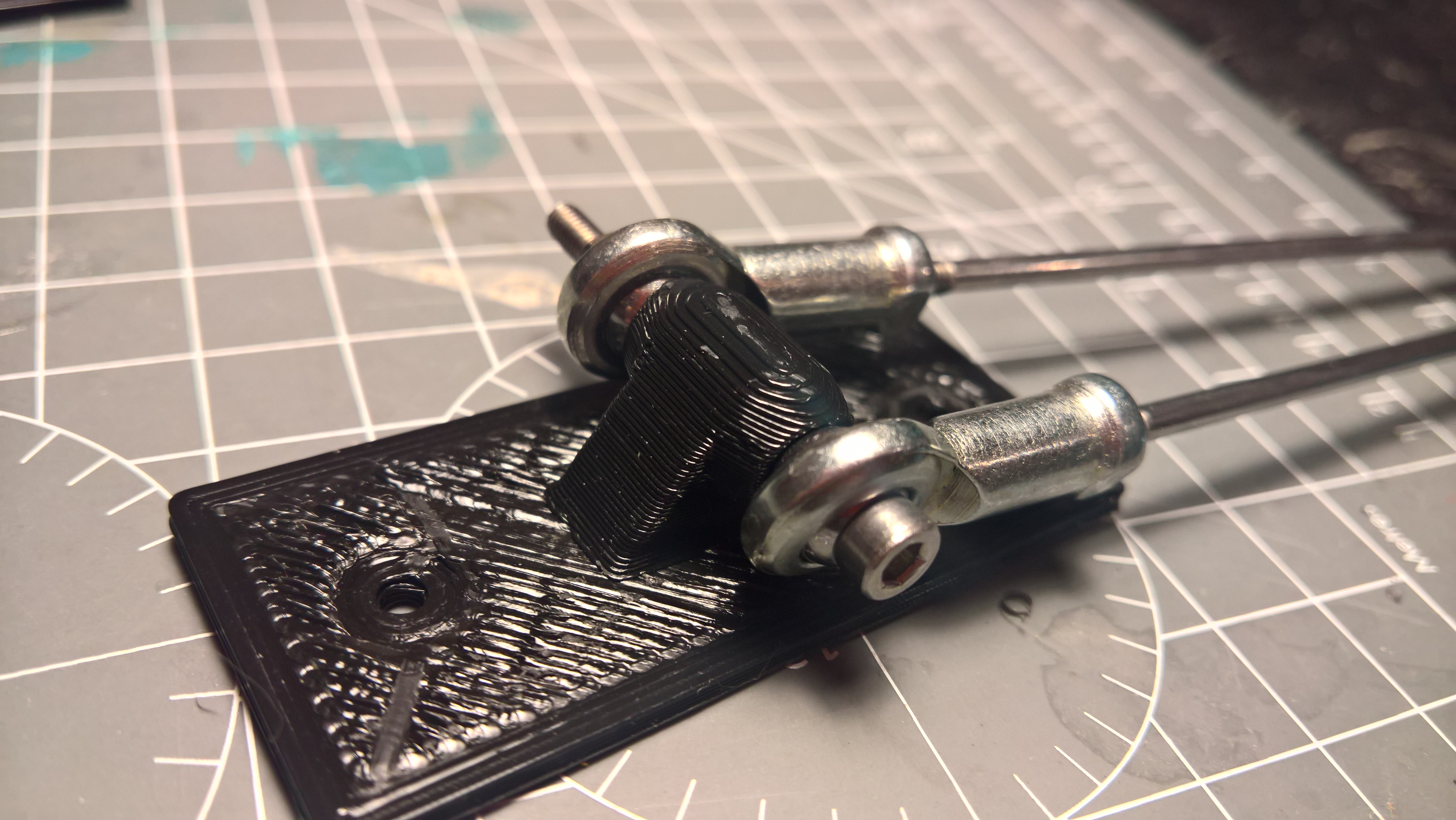
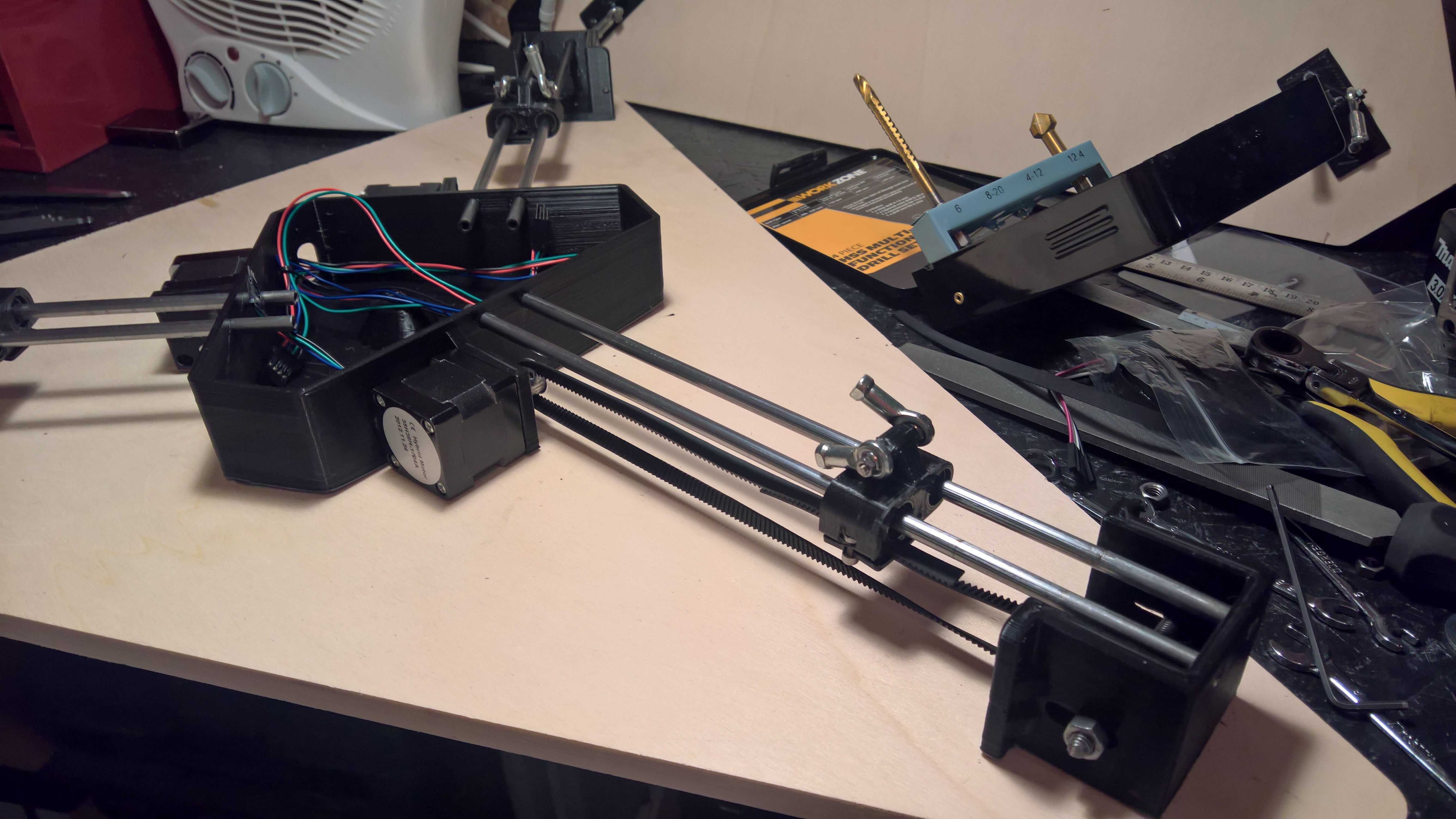
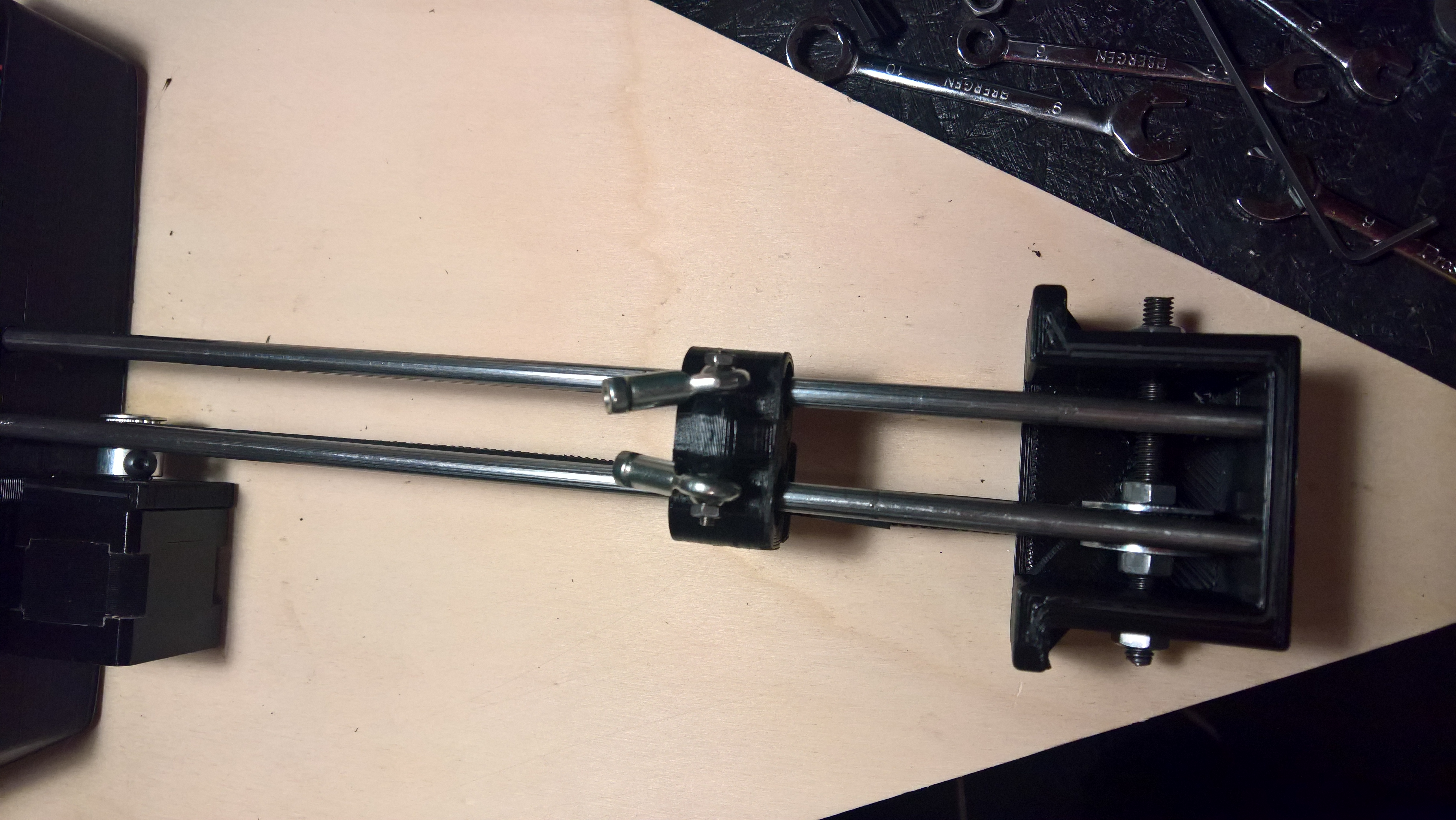
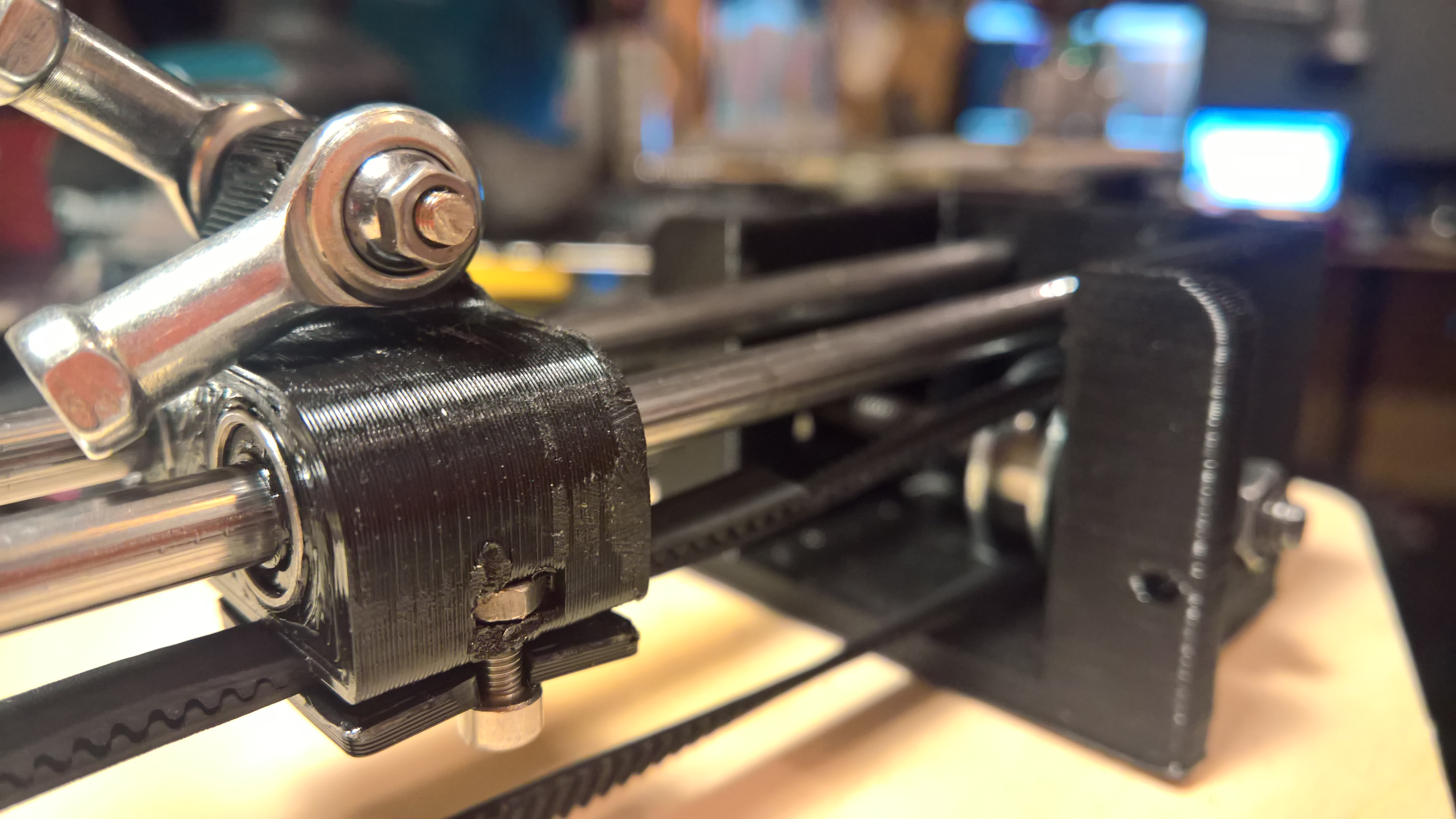
After the not so successful presentation (it didnt work) I had a week out and reviseted the thing. I decided that I neeeded two rails for it to run on, and include an idler for the pully as tensioning the belts was a nightmare on v1. I used the some fancy bearigns called rose bud bearings to give me the freedom of movement i needed without having to sacrafice on size, also - the set cost £12 so not worth the hassle redesigning a bad version for 3d printing.
The work is still to be suspended upside down but with the new components it sort of suspends itslef fo a little while as it was originaly envisaged. The rails are a little rubbish (well, the bearings) as they dont really roll freely - and have ground a few grooves into the steel rod!
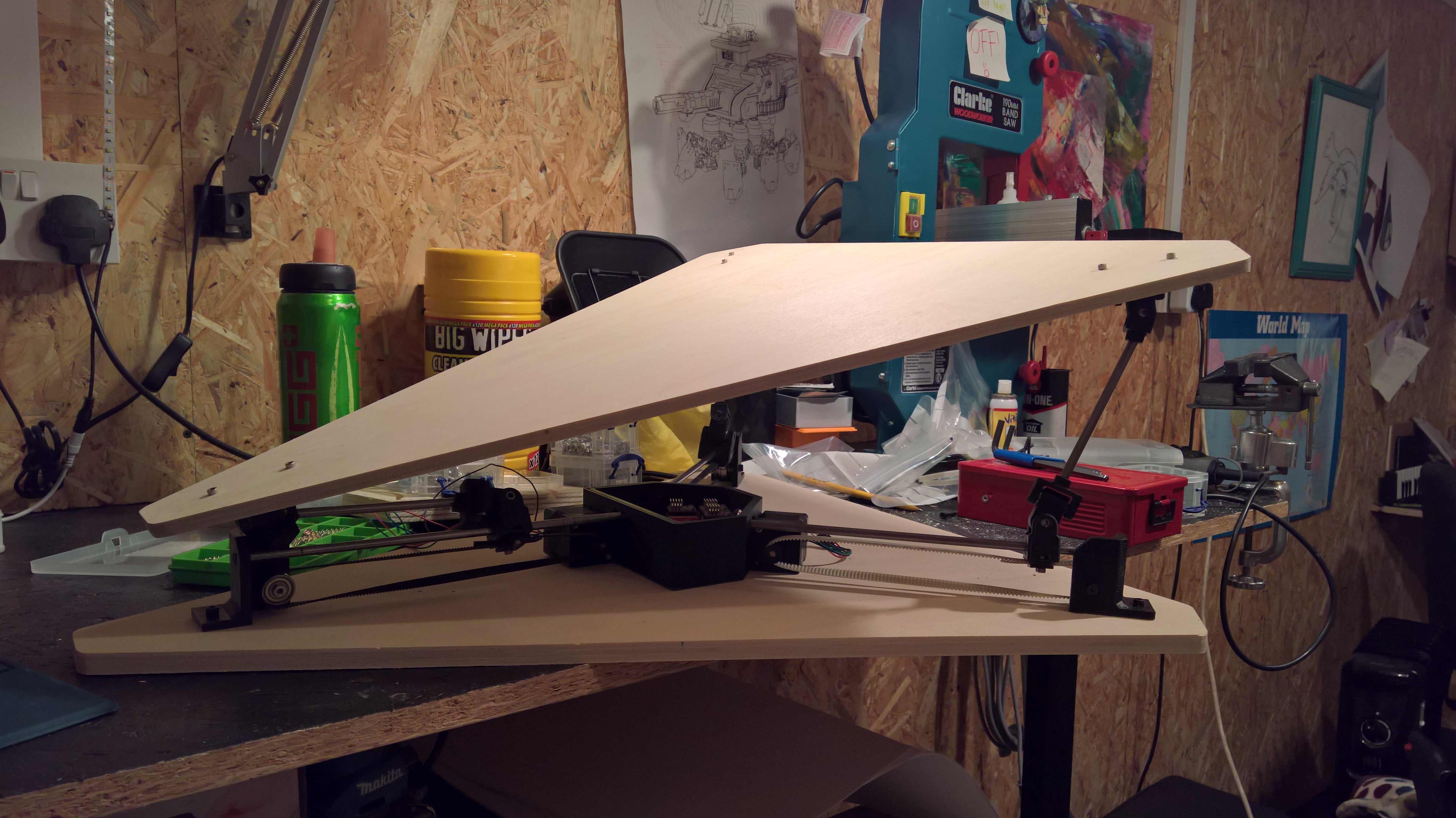
Overall I am now, finally happy with the work. It really is only a story away from being a motor moving a carrige along a rail (a simple test rig tbh) BUT I think that as a working prototype for a larger instilation - it works pretty well. I would obviously liked to have started sooner, but I blame external factors for that, obviously not me! I did work my butt off, but if thats not in the right direction, then its time wasted.
Reference
I pretty much used this guy exclusivly for the wiring
Atmos iTech - the music in the video is terrible though.
The library I used was accelStepper
http://www.airspayce.com/mikem/arduino/AccelStepper/
#CODE
// MultiStepper.pde
// -*- mode: C++ -*-
//
// Shows how to multiple simultaneous steppers
// Runs one stepper forwards and backwards, accelerating and decelerating
// at the limits. Runs other steppers at the same time
//
// Copyright (C) 2009 Mike McCauley
// $Id: MultiStepper.pde,v 1.1 2011/01/05 01:51:01 mikem Exp mikem $
//Modified to run three motors using pot / sliders on analog 0,1,2.
//mapped vals for specif setup, using GT2 belts and 20 tooth puleys.
//option to smooth the vals to stop the grinding! Steppers @1:8 stepping
#include
int val1 = 0;
int long newval1 = 0;
int previous1 = 0;
int val2 = 0;
int previous2 = 0;
int long newval2 = 0;
int val3 = 0;
int previous3 = 0;
int long newval3 = 0;
///////////////
int steps = 256000 ; // (Map value) 1600 = 1 stepper shaft rotation @1/8 stepping
int stepperSpeed = 8000;
int stepperAcceleration = 8000;
/////////////
// defines pins numbers no sheild
//const int stepPin1 = 3;
//const int dirPin1 = 4;
//const int stepPin2 = 5;
//const int dirPin2 = 6;
//const int stepPin3 = 7;
//const int dirPin3 = 8;
// defines pins numbers CNC sheild
const int stepPin1 = 2;
const int dirPin1 = 5;
const int stepPin2 = 3;
const int dirPin2 = 6;
const int stepPin3 = 4;
const int dirPin3 = 7;
// Define some steppers and the pins the will use
AccelStepper stepper1(AccelStepper::DRIVER, 2, 5);
AccelStepper stepper2(AccelStepper::DRIVER, 3, 6);
AccelStepper stepper3(AccelStepper::DRIVER, 4, 7);
void setup()
{
stepper1.setMaxSpeed(stepperSpeed);
stepper1.setAcceleration(stepperAcceleration);
stepper2.setMaxSpeed(stepperSpeed);
stepper2.setAcceleration(stepperAcceleration);
stepper3.setMaxSpeed(stepperSpeed);
stepper3.setAcceleration(stepperAcceleration);
// Serial.begin(115200);
digitalWrite (8 , HIGH); //stepper enable on CNC shield
}
void loop() {
int tempVal1, tempVal2, tempVal3 = 0; //analogRead(A0); // Read Potentiometer current value
//to smooth out the vals, at the expence of responcivness
// for (int i = 0; i < 2; i++) {
// tempVal1 = tempVal1 + analogRead(A0); // Read Potentiometer current value
// tempVal2 = tempVal2 + analogRead(A1); // Read Potentiometer current value
// tempVal3 = tempVal3 + analogRead(A2); // Read Potentiometer current value
// }
//
// val1 = tempVal1 / 5;
// val2 = tempVal2 / 5;
// val3 = tempVal3 / 5;
val1 = analogRead(A0);
val2 = analogRead(A1);
val3 = analogRead(A2);
// if (val > previous + 20) {
float newval1 = map(val1, 40, 983, 0, steps);
stepper1.moveTo(newval1);
float newval2 = map(val2, 40, 983, 0, steps);
stepper2.moveTo(newval2);
float newval3 = map(val3, 40, 983, 0, steps);
stepper3.moveTo(newval3);
stepper1.run();
stepper2.run();
stepper3.run();
}